

Page 1

SYSTEM TECHNOLOGY
Doc. No.:
ST/WI/RG/RGX4400
Revision No: 1.0
WORK INSTRUCTION
FOR
RESIDENTIAL GATEWAY
RGX4400
Page 2

SYSTEM TECHNOLOGY
Doc. No.:
ST/WI/RG/RGX4400
Revision No: 1.0
_______________________________________________________________________________________
For internal (TM) only
Table of Contents
1. OBJECTIVE ...................................................................................................................... - 1 -
2. INTRODUCTION .............................................................................................................. - 1 -
3. SCOPE ............................................................................................................................. - 1 -
4. RESIDENTIAL GATEWAY DETAILS ..................................................................................... - 2 -
5. PRE-REQUISITE ............................................................................................................... - 3 -
5.1. Package Contents ..................................................................................................................................................................................... 3
5.2. System Requirement .............................................................................................................................................................................. 3
Features ........................................................................................................................................................................................ 3
Application ............................................................................................................................................................................ - 3 -
5.3. Safety Precautions ............................................................................................................................................................................. - 4 -
5.4. Hardware Description and Installation .......................................................................................................................................... 5
Front Panel & LED Status ........................................................................................................................................................
Rear Panel & Interfaces Description ..................................................................................................................................
5.5 Installation .................................................................................................................................................................................................. 7
Hardware Installation ............................................................................................................................................................. 7
Wireless Installation Considerations ............................................................................................................................... 7
Roaming ........................................................................................................................................................................................ 8
6. WEB CONFIGURATION ........................................................................................................ 9
6.1. Logging in to the wireless Router ..................................................................................................................................................... 9
6.1.1 Esay Setup .......................................................................................................................................................................... 9
6.1.2 Configuration of Dynamic Account ...................................................................................................................... 10
6.1.3 Configuration of Static Account ............................................................................................................................. 11
6.2. LAN Setup ................................................................................................................................................................................................. 12
6.2.1 LAN Basic ........................................................................................................................................................................ 12
6.2.2 IPVPN ................................................................................................................................................................................ 13
6.2.3 WAN ................................................................................................................................................................................... 14
6.2.4 Port Mapping ................................................................................................................................................................. 17
6.2.5 IP VLAN TAG .................................................................................................................................................................. 19
6.2.6 IPv6 LAN .......................................................................................................................................................................... 20
6.3. Wireless Configuration ....................................................................................................................................................................... 21
6.3.1 2.4GHz Basic Configuration....…………….……………………………………………………………………………....21
6.3.2 WLAN Advanced Setting……………………………………………………………………………………………………23
6.3.3 WLAN Security Settings…………………………………………………………………………………………………….24
6.3.4 WLAN Access Control………………………………………………………………………………………………………..25
6.3.5 WI-FI Protected Setup……………………………………………………………………………………………………….26
6.3.6 5GHz Basic Configuration………………………………………………………………………………………………….27
6.3.2 WLAN Advanced Setting…………………………………………………………………………………………………….29
6.3.3 WLAN Security Settings……………………………………………………………………………………………………..30
6.3.5 WI-FI Protected Setup………………………………………………………………………………………………………..32
6.4. Service Configuration .......................................................................................................................................................................... 33
6.4.1 DHCP .................................................................................................................................................................................. 33
6.4.2 DHCPv6 ............................................................................................................................................................................. 35
6.4.3 UPNP .................................................................................................................................................................................. 35
6.4.5 RIP ...................................................................................................................................................................................... 35
6.4.6 DLNA .................................................................................................................................................................................. 36
Page 3

SYSTEM TECHNOLOGY
Doc. No.:
ST/WI/RG/RGX4400
Revision No: 1.0
_______________________________________________________________________________________
For internal (TM) only
6.4.6 IGMP Proxy ..................................................................................................................................................................... 36
6.4.7 IGMP Snooping .............................................................................................................................................................. 36
6.4.8 MLD Proxy ....................................................................................................................................................................... 37
6.4.9 MLD Snooping ............................................................................................................................................................... 37
6.4.10 DNS Server ................................................................................................................................................................... 37
6.4.11 Dynamic DNS ............................................................................................................................................................... 38
6.5. Firewall Configuration ........................................................................................................................................................................ 39
6.5.1 ALG ..................................................................................................................................................................................... 39
6.5.2 MAC Filtering ................................................................................................................................................................. 39
6.5.3 Port Forwarding ........................................................................................................................................................... 40
6.5.4 URL Blocking .................................................................................................................................................................. 41
6.5.5 Schedule ........................................................................................................................................................................... 42
6.5.6 Domain Blocking .......................................................................................................................................................... 42
6.5.6 DoS ...................................................................................................................................................................................... 42
6.5.8 DMZ .................................................................................................................................................................................... 43
6.5.9 IPv4/Port Filtering ...................................................................................................................................................... 43
6.5.9 IPv6/Port Filtering ...................................................................................................................................................... 44
6.6. Advanced Configuration ..................................................................................................................................................................... 45
6.6.1 Static route ...................................................................................................................................................................... 45
6.6.2 SNMP ................................................................................................................................................................................. 46
6.6.3 Remote Access ............................................................................................................................................................... 46
6.6.4 IP UNNumber ................................................................................................................................................................. 47
6.6.5 QoS ...................................................................................................................................................................................... 47
6.6.6 QoS Classification ......................................................................................................................................................... 48
6.6.7 Traffic Shaping .............................................................................................................................................................. 48
6.6.8 RADVD .............................................................................................................................................................................. 49
6.6.9 Print Server..................................................................................................................................................................... 49
6.6.10 FTP Server .................................................................................................................................................................... 50
6.6.11 Download Master ...................................................................................................................................................... 50
6.6.12 Download Master BiT .............................................................................................................................................. 51
6.7. Maintenance ............................................................................................................................................................................................ 52
6.7.1 Reset/Reboot ................................................................................................................................................................. 52
6.7.2 Backup/Restore ............................................................................................................................................................ 52
6.7.3 System Log ...................................................................................................................................................................... 52
6.7.4 Password ......................................................................................................................................................................... 53
6.7.5 Firmware Upgrade ...................................................................................................................................................... 53
6.7.6 ACL ..................................................................................................................................................................................... 53
6.7.7 Time Zone ........................................................................................................................................................................ 54
6.7.8 TR-069 .............................................................................................................................................................................. 54
6.7.9 Ping & Ping6 ................................................................................................................................................................... 55
6.7.10 Tracert & Tracert6 .................................................................................................................................................... 55
6.8. Status .......................................................................................................................................................................................................... 56
6.8.1 Device Status ................................................................................................................................................................... 56
6.8.2 IPv6 ..................................................................................................................................................................................... 56
6.8.3 WLAN Status of 2.4 GHz ............................................................................................................................................. 57
6.8.4 WLAN Status of 5 GHz ................................................................................................................................................. 57
6.8.5 Interface Statistic .......................................................................................................................................................... 58
6.8.6 USB Status ........................................................................................................................................................................ 58
6.8.7 ARP Table ......................................................................................................................................................................... 59
Page 4

SYSTEM TECHNOLOGY
Doc. No.:
ST/WI/RG/RGX4400
Revision No: 1.0
_______________________________________________________________________________________
For internal (TM) only
7. CONFIGURING THE IP ADDRESS IN WINDOWS XP .............................................................. 60
8. TROUBLESHOOTING .......................................................................................................... 62
9. NETWORKING BASICS ....................................................................................................... 65
9.1. Checking Your IP Address ................................................................................................................................................................. 65
9.2. Statically Assigning an IP Address ................................................................................................................................................. 66
10. TECHNICAL SPECIFICATIONS ............................................................................................... 67
Page 5

SYSTEM TECHNOLOGY
Doc. No.:
ST/WI/RG/RGX4400
Revision No: 1.0
- 1 -
1. OBJECTIVE
The objective of this document is to carry out the Work Instruction (WI) GUI to provide stepby-step instruction for customer to ensure inter-connection between the Residential
Gateway GUI user configuration and Internet network. This is a mandatory requirement for
all customer equipment before it is connected to UNIFI services.
2. INTRODUCTION
Thank you for purchasing the RGX4400.
The RGX4400 delivers next generation wireless speed and coverage to all your Wi-Fi
devices, offering dual-band Gigabit wireless with all-new 802.11ac Wi-Fi. Its powerful dualcore CPU provides the best performance in both 2.4GHz and 5GHz. The 5GHz band works
at up to 867Mbps, while the 2.4GHz frequency tops 300Mbps, serving an incredible
combined bandwidth of 1167Mbps
The RGX4400 also provides secure wireless communication. It supports not only 64/128-bits
WEP, but also up-to-date encryptions including WPA/WPA2-PSK with TKIP/AES, wireless
MAC filtering and SSID broadcast control to consolidate the wireless network security and
prevent unauthorized wireless connection.
The Web-based user interface of the RGX4400 makes it extremely easy to install and
manage the network. The wireless router supports both DHCP client and server, enabling
system administrators to easily integrate this wireless router into existing network
environments, as well as manage IP assignment, without reconfiguring other stations.
3. SCOPE
This document defines and details the Work Instruction (WI) and implemented technical
support for GUI via configuration mode as defined below:
a. Allowed synchronize to network
To ensure the Residential Gateway is able to synchronize with Public network
(wireless or wired connection) and Private network (wireless connection only) to be
connected simultaneously.
b. Dynamic IP Address & Static IP Address
To ensure the RG is able to support Dynamic IP address and Static IP address.
c. Internet Service (on IPv6)
To ensure the RG is able to surf the Internet without any limitation on IPv6 network.
Page 6
SYSTEM TECHNOLOGY
Doc. No.:
ST/WI/RG/RGX4400
Revision No: 1.0
- 2 -
4. RESIDENTIAL GATEWAY DETAILS
Below are the details of the Residential Gateway:
NO
DESCRIPTION
ADSL MODEM INFORMATION
1
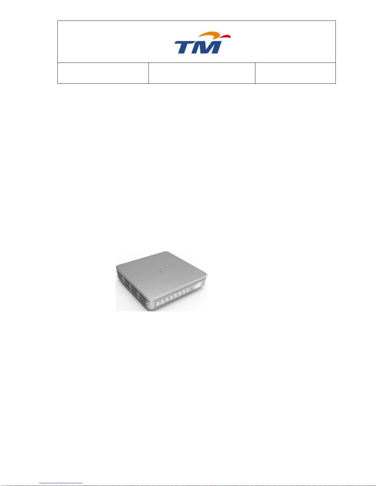
Model name
Residential Gateway RGX4400
2
The colour of RG
Silver Matte
3
Country of origin
China
4
Firmware version
Ver. 2.0.9
5
Input Voltage DC (Vdc) and current
(A)
Input: 100~240 V AC, 50/60 Hz
Output: 12 V DC, 12.0 A
Page 7
SYSTEM TECHNOLOGY
Doc. No.:
ST/WI/RG/RGX4400
Revision No: 1.0
- 3 -
5. PRE-REQUISITE
The following set up is used to carry out the test:
5.1. Package Contents
Please check whether your package list includes the following items:
RGX4400 x1
Power adapter x1
Quick installation guide (QIG) x 1
CD-ROM (DIY Setup Wizard and User Manual) x 1
Blue RJ45 cable x 3
Red Ethernet cable x 1
Yellow RJ-45 cable x 1
Faulty check list x 1
Warranty card x 1
Device info sticker x 3
Note: Using a power supply with a different voltage rating other than the one included with the RGX4400
may cause damage and void the warranty for this product.
5.2. System Requirement
Recommended system requirements are as follows:
Pentium 600 MHz or higher
Memory: 128MB or higher
10M base-T Ethernet or higher
Windows 9X, Windows 2000, Windows XP, Windows ME, Windows NT,
Windows 7, Macintosh OS, and Google OS.
Ethernet network card
Features:
TV over IP (IPTV)
Supports Green WLAN, Energy Efficient Ethernet.
Page 8

SYSTEM TECHNOLOGY
Doc. No.:
ST/WI/RG/RGX4400
Revision No: 1.0
- 4 -
Supports IPv6
WiFi Protection Setup (WPS)
TR-069
Universal Plug and Play (UPnP)
DHCP Server/Client
64/128-bit WEP, WPA/WPA2-PSK and TKIP/AES
Higher data rate broadband sharing
Supports multiple DDNSs.
Quality of Service (QoS) control
Application:
Home and SOHO wireless gateway
Small enterprises
Interactive Television (iTV)
High rate broadband sharing
Broadband Ethernet access
Audio and video streaming and transmission
PC file and application sharing
Network and online gaming
5.3. Safety Cautions
The following instructions are to protect the device from risks and damage caused by
fire and electric power:
Use the type of power that the manual marks.
Use the power adapter in the package.
An overburden power outlet or damaged lines and plugs may cause electric shock
or fire accident. Check the power cords regularly. If you find any damage, replace it
at once.
Proper space left for heat dissipation is necessary to avoid overheating. The holes
on the device are designed for heat dissipation to ensure running normally. Do not
cover these heat dissipation holes.
Do not put this device close to a heat source or high temperature place. Avoid the
device direct exposing sunshine.
Do not put this device close to over damp place. Do not spill any fluid on this
device.
Do not connect this device to PC or electronic product, unless our customer
engineer or your broadband provider instructs you to do this, because any wrong
connection may cause power or fire risk.
Do not place this device on an unstable surface or support.
Page 9
SYSTEM TECHNOLOGY
Doc. No.:
ST/WI/RG/RGX4400
Revision No: 1.0
- 5 -
5.4. Hardware Description
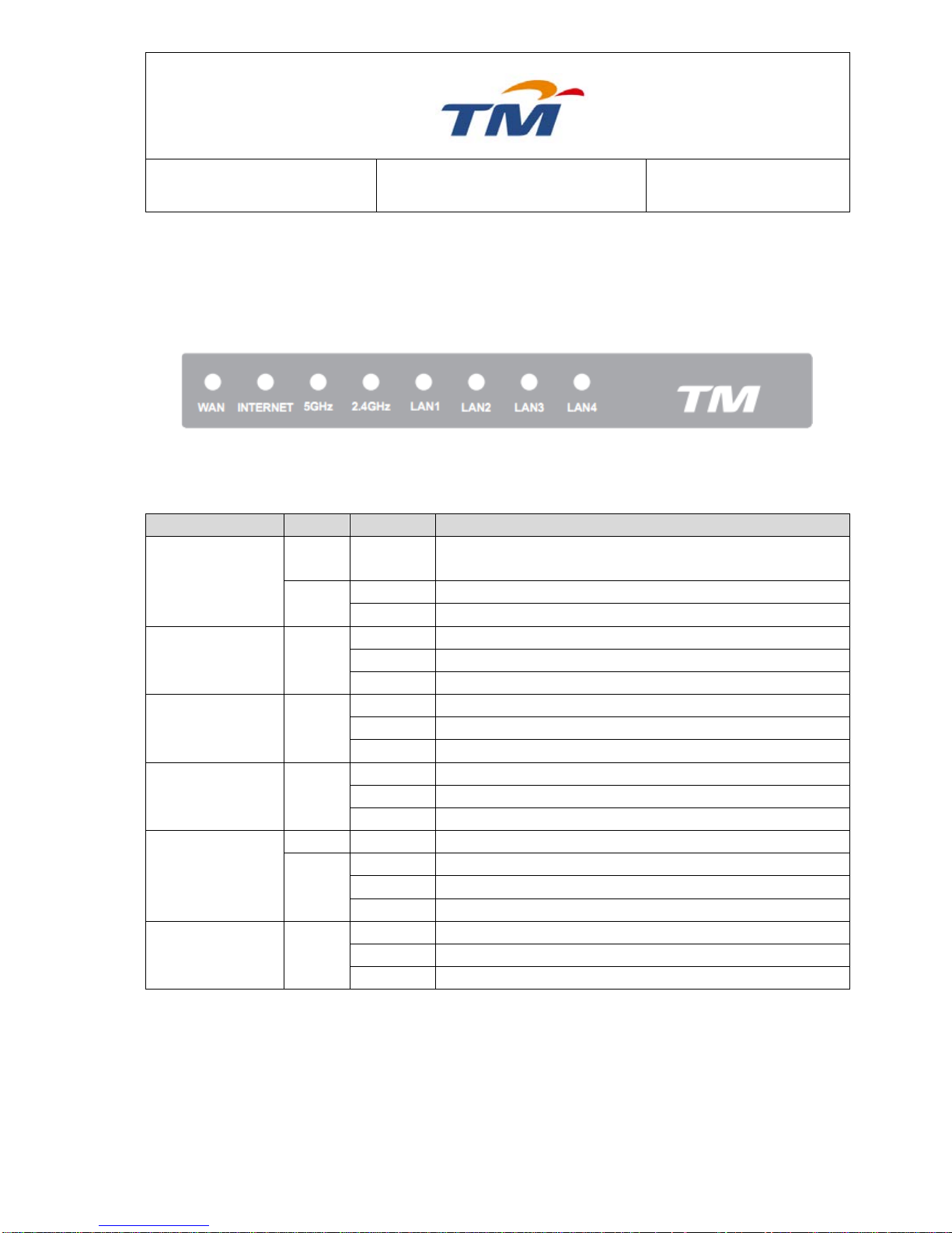
Front Panel & LED Status
Note: Figures in this document are for reference only.
Figure1: Front Panel
The following table describes LEDs of the wireless router.
Indicator
Color
Status
Description
Power (TM Logo)
Red
On
POST testing (60s) is in progress or the device is not
running normally.
White
On
The device is running normally.
Off
Power is off or the device is down.
LAN 4/3/2/1
White
On
LAN connection succeeds.
Blinking
Data is being transmitted through the LAN interface.
Off
No LAN connection.
2.4GHz
White
On
2.4Ghz is Enabled.
Blinking
Data is being transmitted through the 2.4Ghz interface
Off
2.4Ghz is Disabled.
5Ghz
White
On
5Ghz is Enabled.
Blinking
Data is being transmitted through the 5Ghz interface.
Off
5Ghz is Disabled.
INTERNET
Red
On
Internet connection failed.
White
On
Internet line is connected.
Blinking
Data transmission.
Off
Internet line is disconnected.
WAN
White
On
WAN connection succeeds.
Blinking
Data is being transmitted through the WAN interface.
Off
No WAN connection.
Page 10
SYSTEM TECHNOLOGY
Doc. No.:
ST/WI/RG/RGX4400
Revision No: 1.0
- 6 -
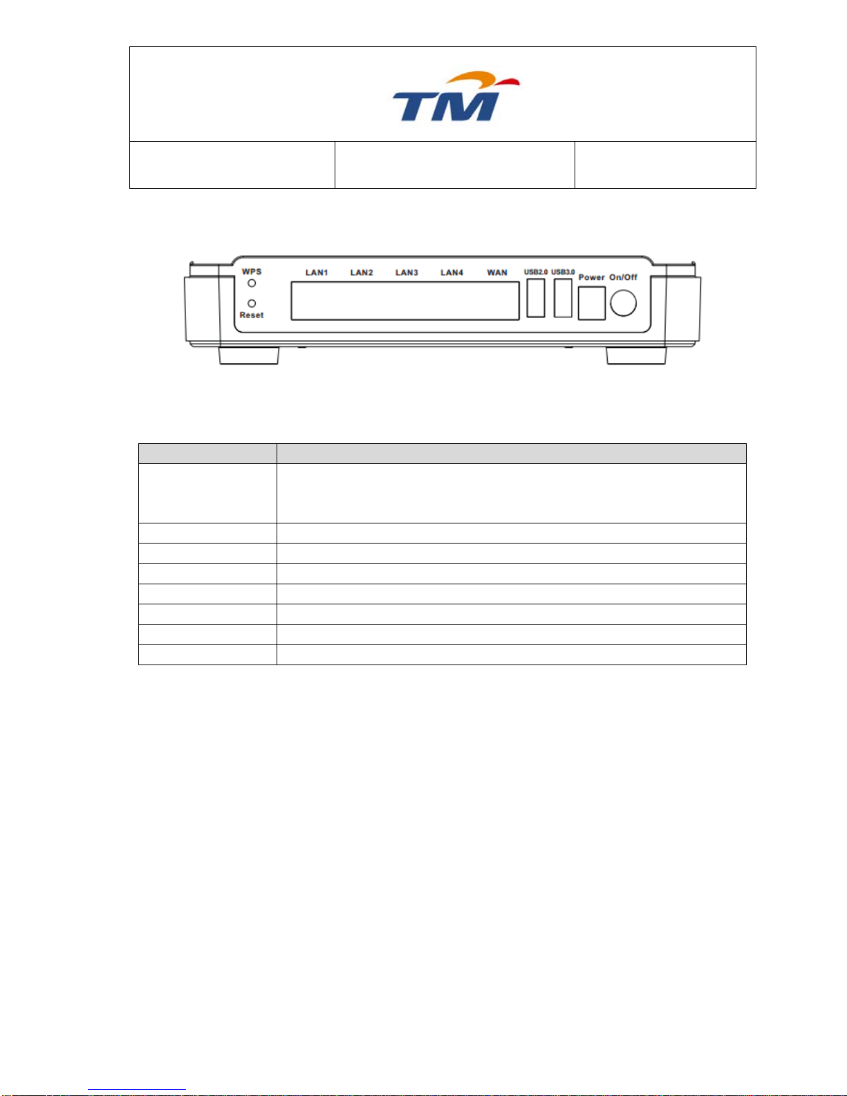
Rear Panel and Interface Description
Figure 2 Rear Panel
The following table describes the interfaces of the device.
Interface/Button
Description
WPS SETUP
This button is used for enabling WPS PBC mode. If WPS is enabled,
press this button, and then the wireless router starts to accept negotiation
of PBC mode.
Reset
Default the modem as the factory setting.
LAN1—LAN4
LAN interface, for connecting a hub, switch, or computer on LAN.
WAN
WAN interface, for connecting WAN or an uplink network device.
USB 2.0
USB interface, for connecting the USB 2.0 device.
USB 3.0
USB interface, for connecting the USB 3.0 device.
Power
Power socket, for connecting the power adapter.
On/Off
Turn on or off the power supply
Caution:
Do not press the Reset button unless you want to clear the current settings. The Reset
button is in a small circular hole on the rear panel. If you want to restore the default
settings, please press the Reset button gently for 10 seconds with a fine needle inserted
into the hole and then release the button. The system reboots and returns to the factory
defaults.
Warning:
The power specification is 12V DC, 2.0A. If the power adapter does not match the
specification, it may damage the device.
Page 11

SYSTEM TECHNOLOGY
Doc. No.:
ST/WI/RG/RGX4400
Revision No: 1.0
- 7 -
5.5. Installation
This is a step-by-step configuration requirement to connecting RGX4400 as defined below:
Hardware Installation
This section will walk you through the installation process. Placement of the wireless router
is very important. Do not place the router in an enclosed area such as a closet, cabinet or in
the attic or garage.
Wireless Installation Considerations
Designed to go up to 100 meters indoors and up to 300 meters outdoors, the wireless router
lets you access your network using a wireless connection from virtually anywhere within the
operating range of your wireless network. However, the number, thickness and location of
walls, ceilings, or other objects that the wireless signals must pass through, may limit the
signal range. Typical ranges vary depending on the types of materials and background radio
frequency (RF) noise in your home or business. To maximize the wireless range of the
router, pay attention to the following basic guidelines:
Keep the number of walls and ceilings between the RGX4400 router and other
network devices to a minimum.
Be aware of the direct line between network devices. Position devices so that the
signal will travel straight through a wall or ceiling (instead of at an angle) for better
reception.
Building materials make a difference. Try to position the wireless Router so that the
signal passes through drywall or open doorways.
Keep your product away from electrical devices or appliances that generate RF noise.
Place the Router on a shelf or desktop. Ideally, you should be able to see the LED
indicators in the front, as you may need to view them for troubleshooting.
For connection between the wireless Router and a computer, hub, router or switch,
the Ethernet cable should be shorter than 100m.
Do not place this device on an unstable surface or support. Do not put this device on
the ground.
Keep the device clean. Avoid exposure to direct sunshine. Avoid any metal on the
device.
To connect the wireless router to a PC, do as follows.
Step1 Connect the antennas to the antenna interfaces.
Step2 Connect one end of the RJ45 cable to the LAN interface of the wireless
router.
Step3 Connect the other end of the RJ45 cable to your PC.
Step4 Connect the power adapter to the Power socket.
Page 12
SYSTEM TECHNOLOGY
Doc. No.:
ST/WI/RG/RGX4400
Revision No: 1.0
- 8 -
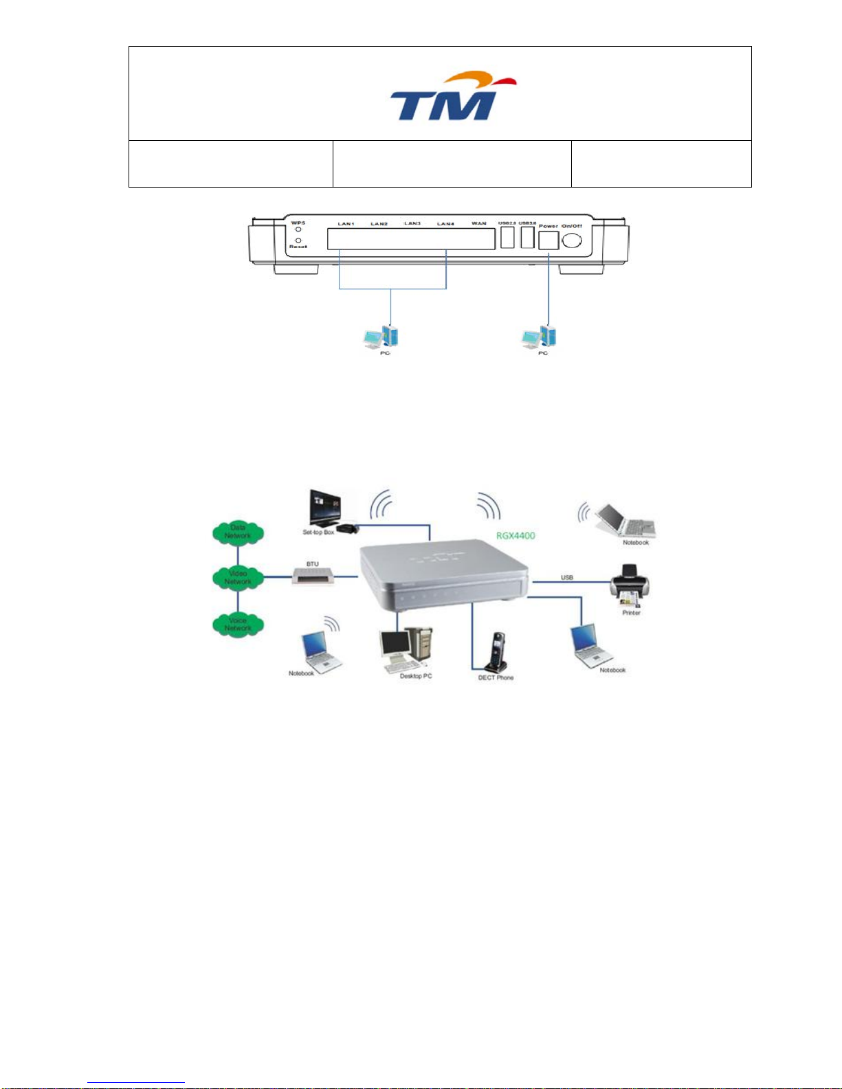
Note: If wireless signal is weak, please put the wireless router to the appropriate place or
adjust the antenna angle.
The wireless router can connect to various network devices. See the following figure:
Roaming
Suppose that several wireless routers run in the same network. Each wireless router serves as a
BSS, and has its coverage. One wireless client terminal (for example, a notebook or PDA) can
realize roaming from one wireless router to another wireless router correctly. In that case, the
wireless client terminal can communicate with the other devices within the coverage of wireless
routers.
In order to realize the wireless client roaming among different wireless routers, you need to
set the wireless router properly. Do as follows:
Set the same SSID for different wireless routers.
SSIDs of all computers and PDAs should be consistent with those of the wireless
routers.
If the encryption function is enabled, all wireless routers should be configured with the
same encryption mode and the encryption key.
Please put the wireless routers in the appropriate places for a better network
coverage.
Page 13
SYSTEM TECHNOLOGY
Doc. No.:
ST/WI/RG/RGX4400
Revision No: 1.0
- 9 -
6.0 Web Configuration
This section shows you how to configure your new RGX4400 wireless router using the Webbased configuration page.
6.1 Logging In to the wireless router
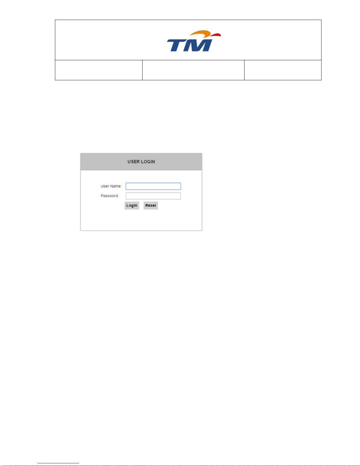
Step1 To access the configuration page
of the wireless router, open a
Web browser such as Internet
Explorer (IE) and enter
http://192.168.0.1 (IP address of
the wireless router) in the address
bar.
Step2 Enter admin in the Username
field and leave the password
blank by default.
Step3 Click Login to log in to the Web
page.
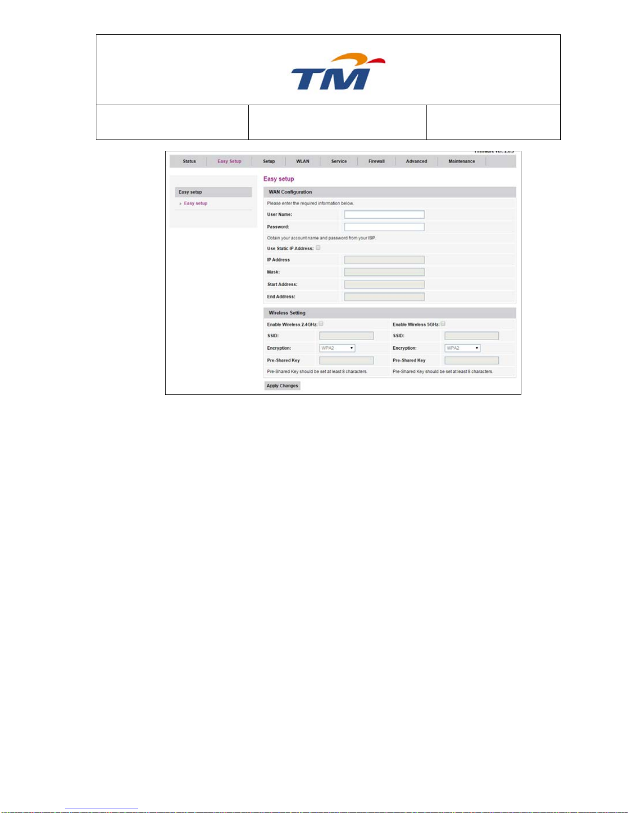
6.1.1 Easy Setup
Choose Easy Setup and the first page of the Easy Setup appears. Connection Type and Service
Type are already configured and cannot be modified. The default connection type is PPPoE.
Page 14
SYSTEM TECHNOLOGY
Doc. No.:
ST/WI/RG/RGX4400
Revision No: 1.0
- 10 -
Username
It is the user name for log in through PPPoE.
Password
It is the password for log in through PPPoE.
Use Static IP Address
Tick the Check Box; if you need to set a static IP Address for
PPPoE connection.
IP Address
Static IP Address Provide by your ISP.
Mask
Subnet Mask.
Start Address
The start IP address of the IP address pool from which the
DHCP server assigns the IP address to the PC.
End Address
The end IP address of the IP address pool of the DHCP server.
Enable Wireless 2.4Ghz &
5Ghz
Tick the Check Box to Enable 2.4Ghz or 5Ghz Wireless.
SSID
Wireless Name for 2.4Ghz & 5Ghz
Encryption
Select the key type
Pre-Shared Key
Set the Pre-Shared key (Password)
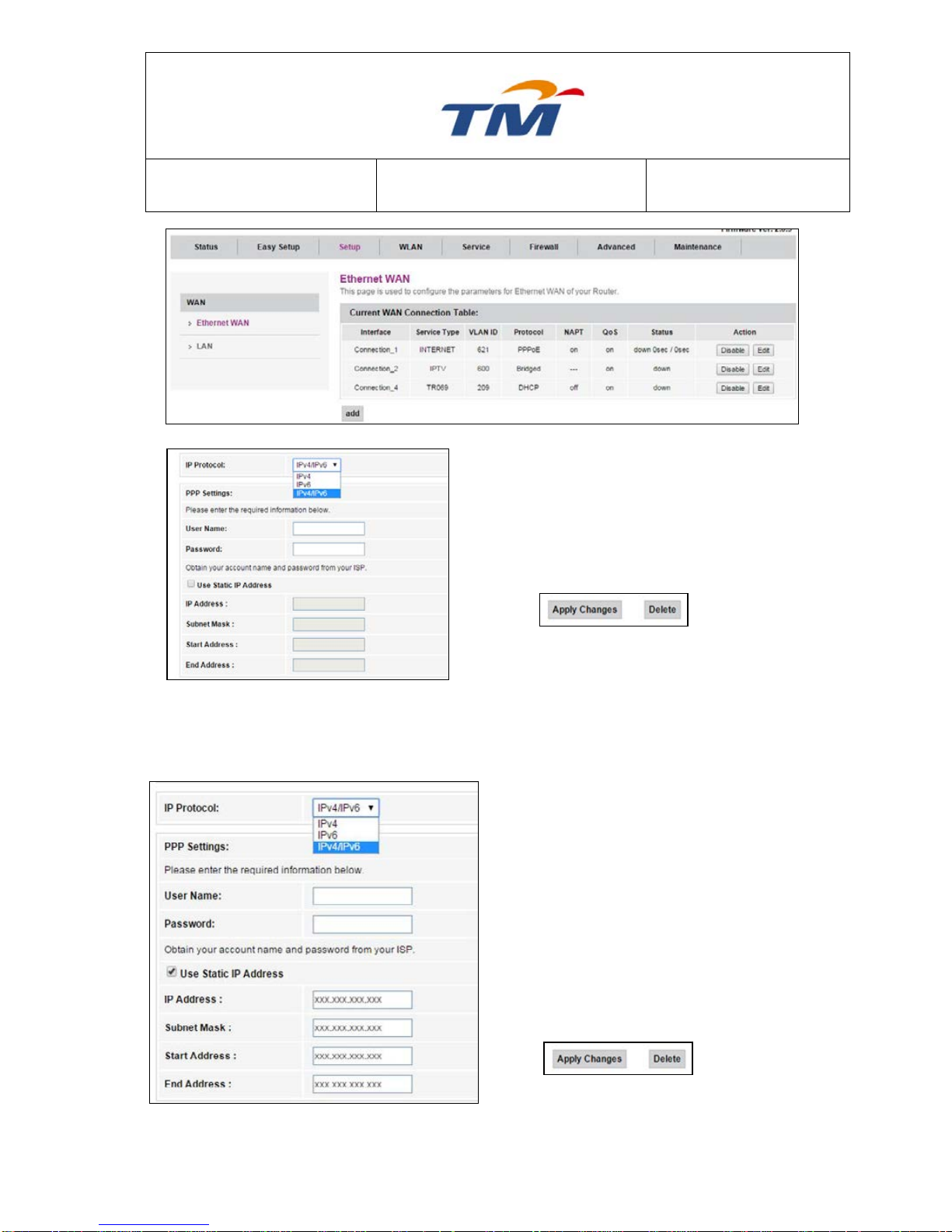
6.1.2 Configuration of Dynamic Account
Choose Setup, Then Select Ethernet WAN to configure PPPoE Setting
Page 15
SYSTEM TECHNOLOGY
Doc. No.:
ST/WI/RG/RGX4400
Revision No: 1.0
- 11 -
Step1 Select the IP Protocol, By Default is IPv4 &
IPv6
Step2 Key In the PPPoE Username (Provided by
your Internet Service Provider)
Step3 Key In the PPPoE Password (Provided by
your Internet Service Provider)
Step4 Click Apply Changes at the bottom of the
page.
6.1.3 Configuration of Static Account
Step1 Select the IP Protocol, By Default is IPv4 &
IPv6
Step2 Key In the PPPoE Username (Provided by
your Internet Service Provider)
Step3 Key In the PPPoE Password (Provided by
your Internet Service Provider)
Step4 Tick the Use Static IP Address check box
to key in static IP Address.
Step5 Key In the Static IP Address (Provided by
your Internet Service Provider), Subnet
Mask, Start Address & End Address.
Step6 Click Apply Changes at the bottom of the
page.
Page 16
SYSTEM TECHNOLOGY
Doc. No.:
ST/WI/RG/RGX4400
Revision No: 1.0
- 12 -
6.2 Setup
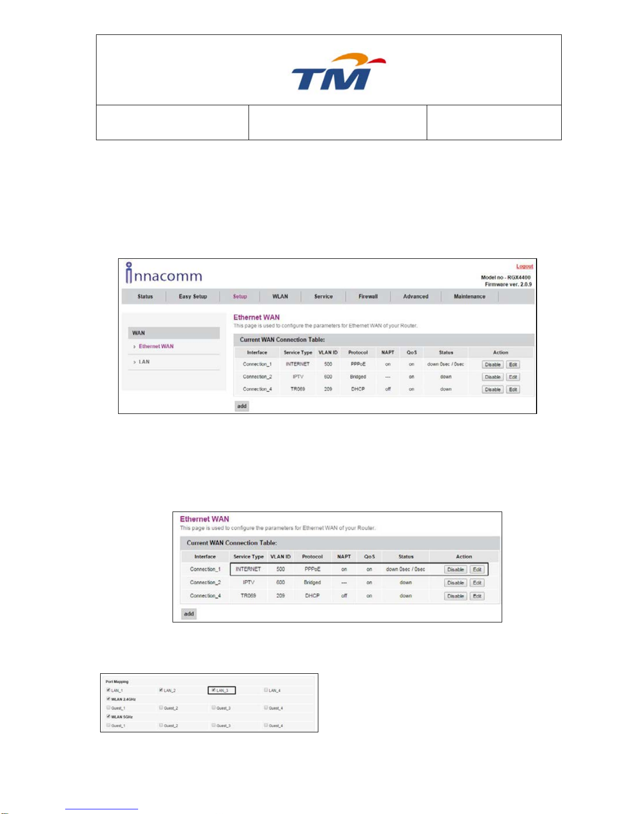
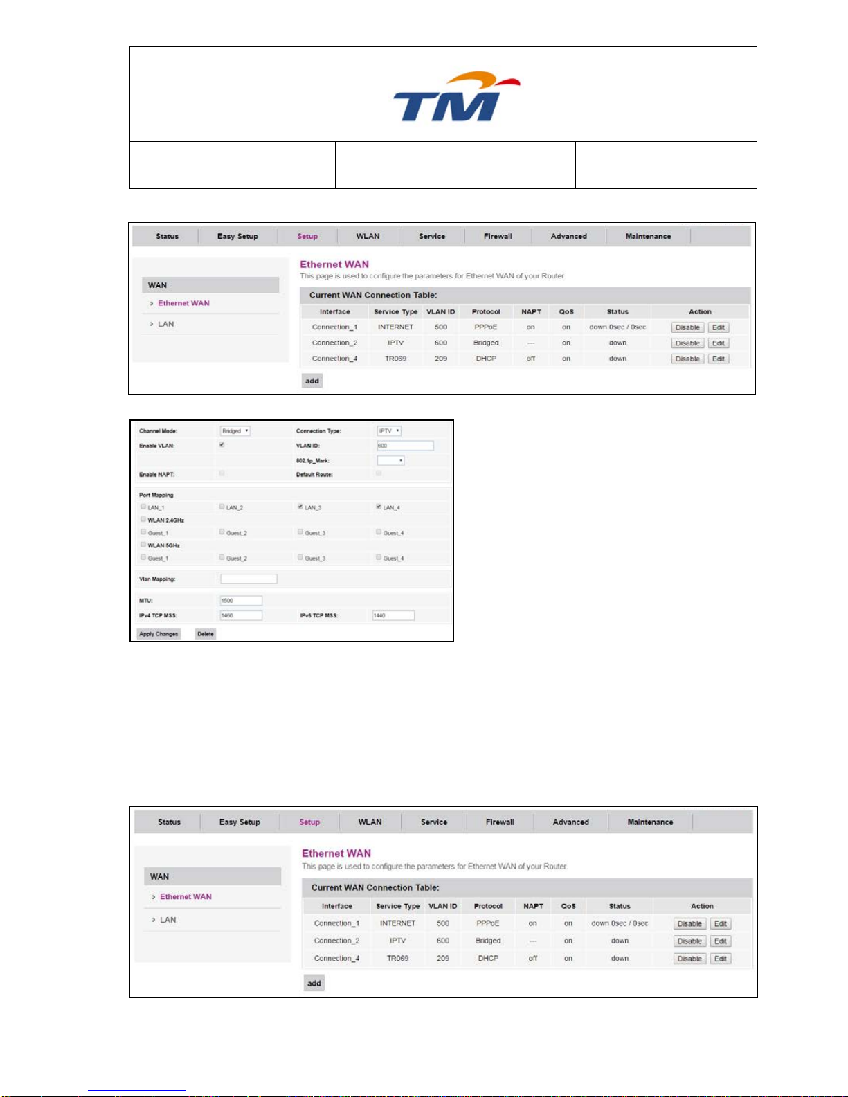
6.2.1 Ethernet WAN
Choose Setup > Ethernet WAN, and the WAN Interface page appears. In this page, you can
add a new WAN connection or edit the pre-set WAN connections. As the WAN Configuration
page appears, there are 3 pre-set WAN connections with the Protocol types are PPPoE,
Bridge, and DHCP.
But before adding a new WAN connection, you need to modify the bound LAN ports of the preset WAN connections as LAN1-LAN4 has been bound, and no available LAN ports for new
WAN connections.
To add a new WAN Connection, do as follow:
Step1 Click Edit of the first pre-set PPPoE WAN connection which the VLAN
ID is 500.
Step2 In the coming page, find the Port
Mapping section as the right figure
appears.
Step3 Uncheck at least one LAN port and
click Apply at the bottom of the page
Page 17
SYSTEM TECHNOLOGY
Doc. No.:
ST/WI/RG/RGX4400
Revision No: 1.0
- 13 -
to go back to the main WAN
connection page.
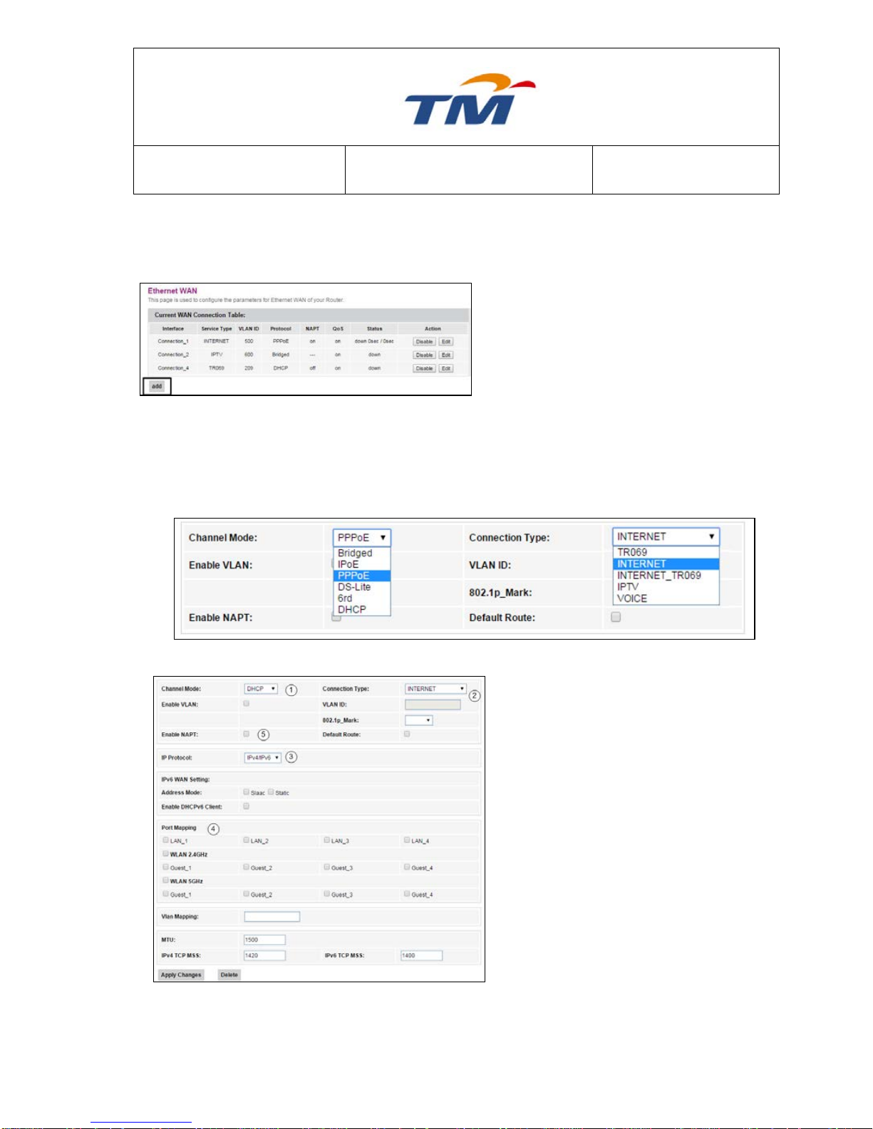
Step4 Click Add in the main page.
Step5 In the coming page, you can configure the parameters of the new WAN connection.
There are 5 Channel Mode in the dropdown list: Bridged, IPoE, PPPoE, DS-Lite,
6rd & DHCP; And 5 Connection Type in the dropdown list: TR069, INTERNET,
INTERNET_TR069, IPTV, & VOICE. You can select one based on the internet
service subscribed from your ISP.
DHCP
1) Set the Connection Type to be DHCP.
2) Set the Service Type to be INTERNET
or TR069_INTERNET.
3) Set the IP Version to be IPv4 or
IPv4&6.
4) If you want to bind this DHCP
connection to a port, select that port.
You can also bind this connection to
more than one port.
5) Enable or disable the VLAN Tagging
of this connection. If you select Enable
VLAN Tagging, you’ll be required to
enter the VLAN ID for marking the
packet.
Page 18
SYSTEM TECHNOLOGY
Doc. No.:
ST/WI/RG/RGX4400
Revision No: 1.0
- 14 -
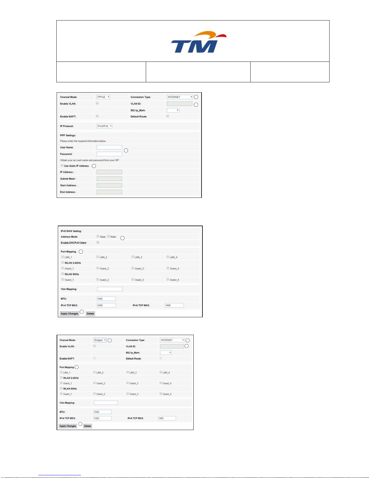
PPPoE
1) Selected connection under PPPoE
type.
2) Enable or disable the VLAN
Tagging of this connection. If you
select Enable VLAN Tagging, you’ll
be required to enter the VLAN ID
for marking the packet.
3) Key in the PPPoE Username &
PPPoE Password (Provided by
your Internet Service Provider).
4) Tick the Use Static IP Address
checkbox to enable Static IP. Fill
the blanks in the right figure with
the information provided by your
ISP.
5) Select Which IPv6 Address Mode
needed to display.
6) If you want to bind this Static IP
connection to a port, select that
port. You can also bind this
connection to more than one port
or to the wireless u needed
7) Save Configuration by click Apply
Changes at the bottom of the
page.
Bridge
1) Set the Connection Type to be Bridge.
2) Set the Service Type to be INTERNET,
TR069, IPTV or VOICE.
3) Enable or disable the VLAN Tagging of this
connection. If you select Enable VLAN,
you’ll be required to enter the VLAN ID for
mark the packet of this connection.
4) Select the Port or Wireless u need to bind
with this connection.
5) Save configuration by click Apply
Changes in the bottom of the page
5
4
2
3
1
1
2
3
4
76
5
7
Page 19
SYSTEM TECHNOLOGY
Doc. No.:
ST/WI/RG/RGX4400
Revision No: 1.0
- 15 -
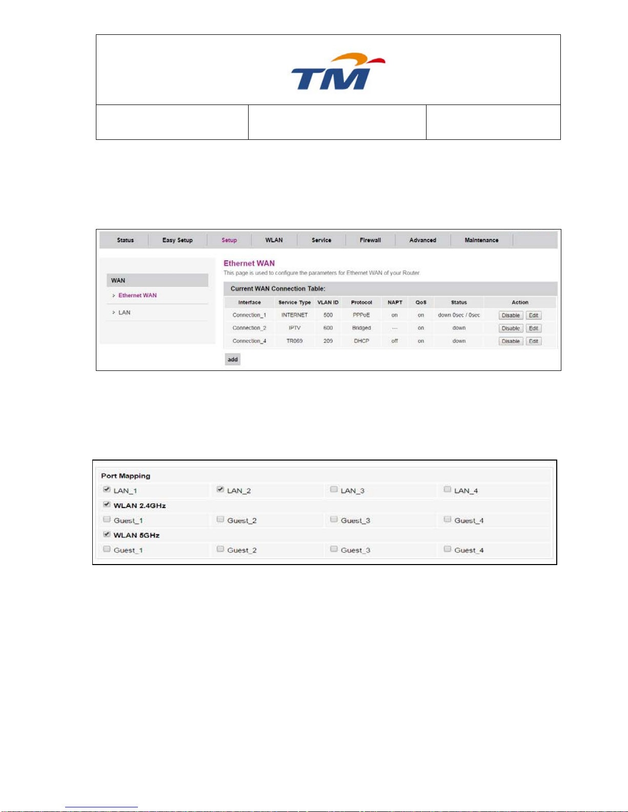
6.2.2 Port Mapping
Choose Setup > Ethernet WAN, and the WAN Configuration page appears.
All WAN will have its own Port Mapping. They cannot be overlap and cannot be empty
If you want to move LAN3 to VLAN 600, you will have to remove it from VLAN 500 and add it on
VLAN 600.
Click Edit at Connection_1
Go to Port Mapping and Uncheck the LAN3 Checkbox.
Click Apply Changes at bottom of the page to save the configuration.
Then Click Edit at Connection_2
Page 20
SYSTEM TECHNOLOGY
Doc. No.:
ST/WI/RG/RGX4400
Revision No: 1.0
- 16 -
Go to Port Mapping and tick on the LAN_3
Checkbox.
Click Apply Changes to save the
configuration.
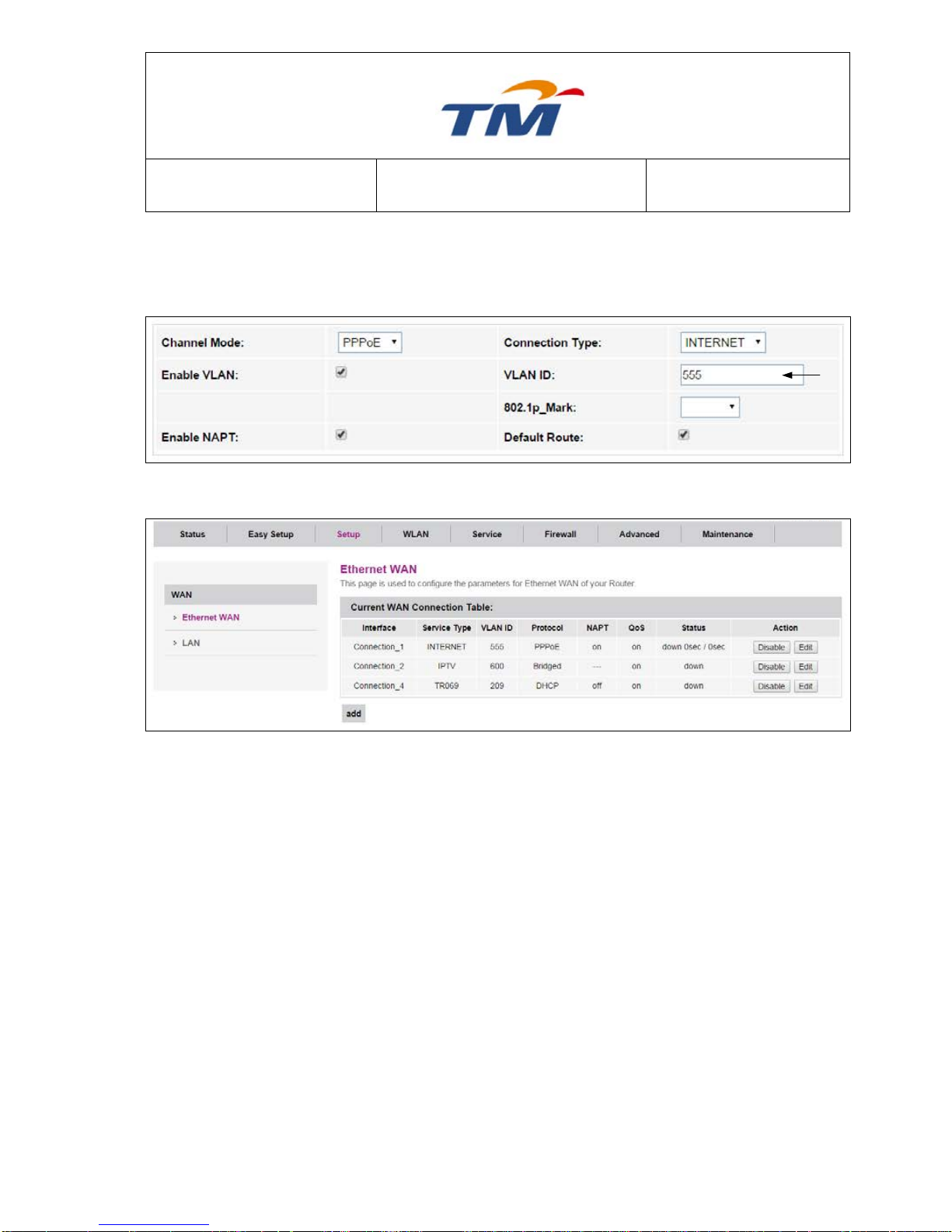
6.2.3 IP VLAN TAG
Choose Setup > WAN, and the WAN Configuration page appears.
Page 21
SYSTEM TECHNOLOGY
Doc. No.:
ST/WI/RG/RGX4400
Revision No: 1.0
- 17 -
If u want to change the VLAN ID from 500 to other VLAN, Example to VLAN 555.
Click Edit at Connection_1
Go to VLAN; change the VLAN ID to VLAN 555, Click Apply Changes to save the configuration.
Then the page will go back to WAN, you will able to see the VLAN ID had change from VLAN 500
to VLAN 555.
Page 22
SYSTEM TECHNOLOGY
Doc. No.:
ST/WI/RG/RGX4400
Revision No: 1.0
- 18 -
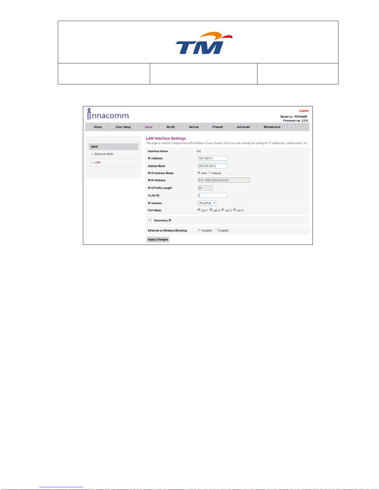
6.2.4 LAN
IP Address the address of the LAN management interface.
Subnet Mask The Subnet Mask for the LAN interface.
IPv6 Address Mode Address Mode for the IPv6 interface.
IPv6 Address IP Address for the LAN interface. Can be edit when
Selected Manual Address Mode.
IPv6 Prefix Length Prefix Length for the IPv6. Can be edit when Selected
Manual Address Mode.
VLAN ID VLAN ID for the interface.
IP Version IP Version for this interface.
Port Mask Port to bind for this interface.
Check Box for Secondary IP Tick the Check box to Enable Secondary IP for this
interface.
Ethernet to Wireless Blocking Disabled or Enabled wireless blocking.
After setting, click Submit to save the settings.
Page 23
SYSTEM TECHNOLOGY
Doc. No.:
ST/WI/RG/RGX4400
Revision No: 1.0
- 19 -
6.3 Wireless Configuration
Wireless configuration includes wireless basic configuration, VAP configuration, WPS configuration
and wireless advanced configuration.
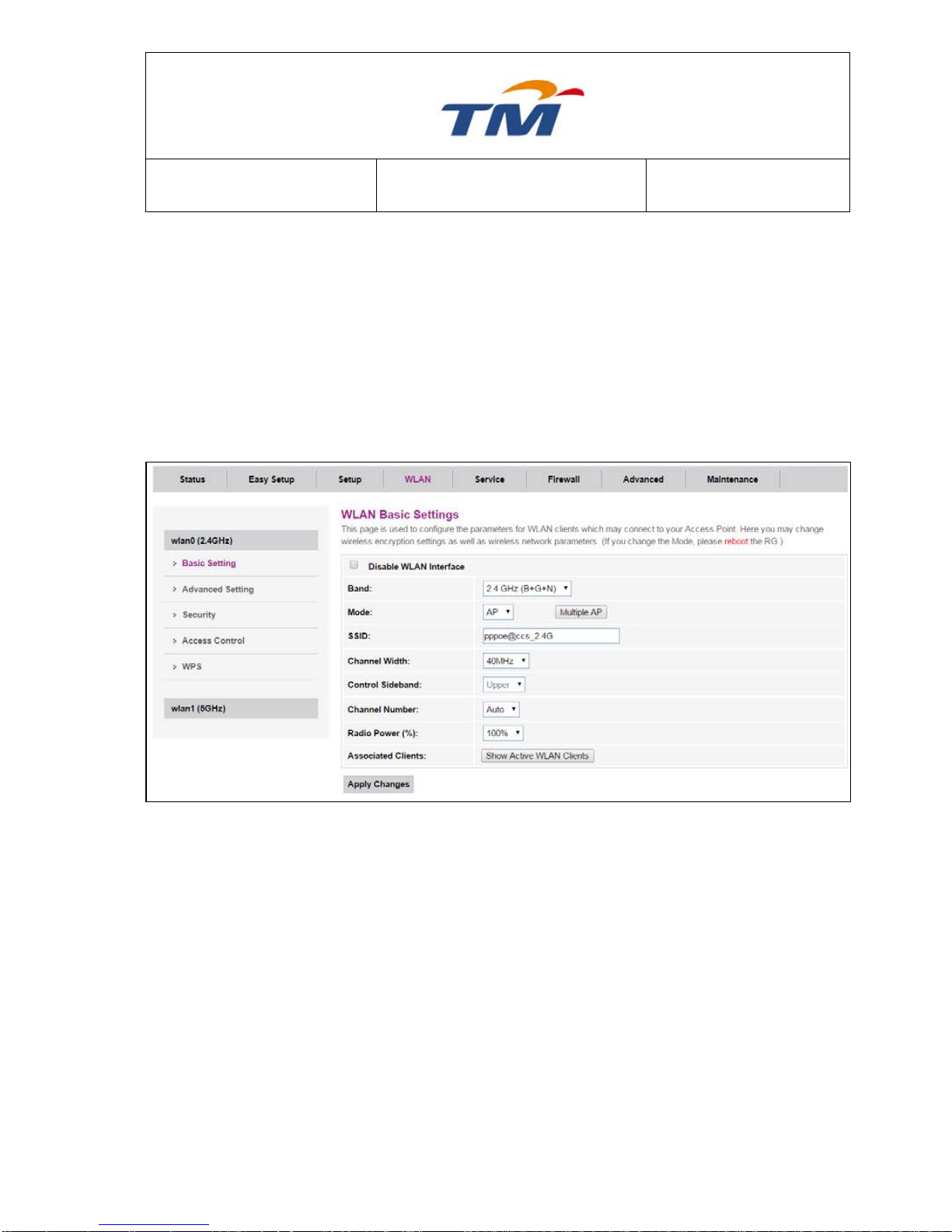
6.3.1 WLAN0(2.4GHz) Basic Configuration
Choose WLAN > Basic, and the wireless 2.4GHz page appears. In this page, you can enable or
disable 2.4G wireless, Tick Disable WLAN Interface to disable the wireless 2.4Ghz
Band Wireless Band for 2.4GHz.
Mode Wireless Mode for this interface.
Multiple AP Click to configure more SSID for 2.4Ghz interface.
SSID SSID Name for the 1
st
Interface.
Channel Width Can select 20, 40, or 20/40, in MHz.
Control Sideband Upper Channel Band or Lower Channel Band to be selected
Channel Number Select the proper channel from the drop-down list. The default value
is Auto.
Radio Power (%) You can select 100%, 70%, 50%, 35% and 15%. The default
value is 100%.
Associated Clients Click to check all Active WLAN Clients
After setting, click Submit to apply the settings.
Page 24
SYSTEM TECHNOLOGY
Doc. No.:
ST/WI/RG/RGX4400
Revision No: 1.0
- 20 -
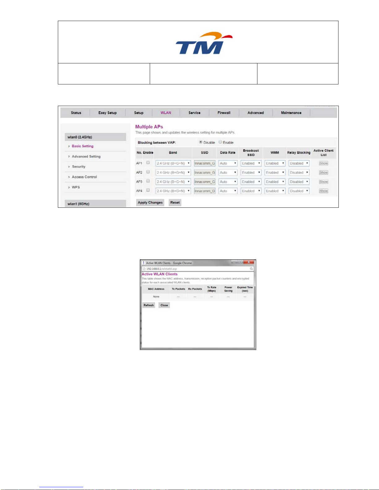
Multiple AP
By Clicking Multiple AP Button, this page will be shown, you can create up to 4 MBSSID under
2.4Ghz Wireless. Tick the Check Box to Enable the VAP, configure the new SSID to meet your
requirement.
Show Active WLAN Clients
After Clicking the Show Active WLAN Clients Button, this page will Pop out, you will be able to
see any active clients that connected to this VAP.
Page 25

SYSTEM TECHNOLOGY
Doc. No.:
ST/WI/RG/RGX4400
Revision No: 1.0
- 21 -
6.3.2 WLAN Advanced Setting
Fragment Threshold
The maximum length for a packet fragment. The default value is
2346.
RTS Threshold
The threshold value for sending the RTS/CTS frame. The default
value is 2346 Bytes.
Beacon Interval
The interval for the device sending the beacon frame.
Data Rate
Select the date Rate in the dropdown list that needed, default is Auto
mode.
Preamble Type
The Preamble type in 802.11 based wireless communication defines
the length of the CRC (Cyclic Redundancy Check) block for
communication between the Access Point and roaming wireless
adapters. CRC is a common technique for detecting data
transmission errors.
Broadcast SSID
To Broadcast SSID name or Disable broadcast SSID name.
Relay Blocking
Enabled or Disabled the Relay Blocking features.
Protection
Protection for this 2.4Ghz interface
Aggregation
Aggregation is an alternate term for route summarization, which is a
method used to minimize the number of routing tables required in an
IP network.
Short GI
Used to ensure that distinct transmissions do not interfere with one
another.
6.3.3 WLAN Security Settings
Page 26

SYSTEM TECHNOLOGY
Doc. No.:
ST/WI/RG/RGX4400
Revision No: 1.0
- 22 -
SSID
Click the dropdown list to select the SSID to be configured.
Encryption
None, WEP, WPA2, and WPA2 Mixed can be selected in the
dropdown list.
Authentication Mode
Enterprise type or Personal type to be selected.
WPA2 Cipher Suite
TKIP & AES can be selected
Pre-Shared Key Format
Passphrase & HEX can be selected
Pre-Shared Key
Password for the SSID
WEP
802.1x Authentication
Tick to Enable.
Authentication
Select which type of Authentication to be used
for this wireless interface
Key Length
64-bits For 10 hex digits or 5 ascii & 128-bits
For 26 hex digits or 13 ascii.
Key Format
Selected 64-bits dropdown only showed ASCII
(5 characters) & HEX (10 characters). Selected
128-Bits dropdown only showed ASCII (13
Characters) & HEX (26 Characters).
Encryption Key
Password for SSID
WPA2 Mixed
Page 27

SYSTEM TECHNOLOGY
Doc. No.:
ST/WI/RG/RGX4400
Revision No: 1.0
- 23 -
SSID
Click the dropdown list to select the SSID to be configure
Encryption
None, WEP, WPA2, and WPA2 Mixed can be selected in the
dropdown list.
Authentication Mode
Enterprise type or Personal type to be selected.
WPA Cipher Suite
TKIP & AES can be selected.
WPA2 Cipher Suite
TKIP & AES can be selected.
Pre-Shared Key Format
Passphrase & HEX can be selected in the dropdown.
Pre-Shared Key
Password for the SSID.
6.3.4 WLAN Access Control
In this Page, you can enable or disable Access Control. By clicking the dropdown list you can
select allow listed or deny listed, If Access Control is disabled, the function of Add MAC List is
disabled.
If MAC Access Control is enabled, you can configure allow or deny list by adding MAC address,
the MAC address can be seen in the list at the page.
Page 28

SYSTEM TECHNOLOGY
Doc. No.:
ST/WI/RG/RGX4400
Revision No: 1.0
- 24 -
To delete a MAC address in the MAC list, tick the check box then click Delete Selected or clicking
Delete All to delete all MAC address.
6.3.5 WI-FI Protected Setup
In this page, the WPS switch is supplied, Tick Disable WLAN Interface to disable the WPS
Function. By default this Function is Disable.
WPS Status
Tick to keep the existing wireless settings
Auto-lock-down state
Self-PIN Number
To change the PIN Number for WPS Key
Push Button Configuration
To Run WPS in client.
Show Key Check Box
Tick to see the password set at security page
Client PIN Number
Generate the PIN Number
6.3.6 5GHz Basic Configuration
Choose WLAN > Basic, and the wireless 5GHz page appears. In this page, you can enable or
disable 5G wireless, Tick Disable WLAN Interface to enable the wireless 5Ghz.
Page 29

SYSTEM TECHNOLOGY
Doc. No.:
ST/WI/RG/RGX4400
Revision No: 1.0
- 25 -
Band Wireless Band for 5GHz.
Mode Wireless Mode for this interface.
Multiple AP Click to configure more SSID for 5Ghz interface.
SSID SSID Name for the 1
st
Interface.
Channel Width Can select 20, 40, or 80, in MHz.
Control Sideband Auto Mode.
Channel Number Select the proper channel from the drop-down list. The default value
is 44.
Radio Power (%) You can select 100%, 70%, 50%, 35% and 15%. The default
value is 100%.
Associated Clients Click to check all Active WLAN Clients
After setting, click Submit to apply the settings.
Multiple AP
Page 30

SYSTEM TECHNOLOGY
Doc. No.:
ST/WI/RG/RGX4400
Revision No: 1.0
- 26 -
By Clicking Multiple AP Button, this page will be shown, you may create up to 4 VAP under 5Ghz
Wireless. Tick the Check Box to Enable the VAP, configure the new SSID to meet your
requirement.
Show Active WLAN Clients
After Clicking the Show Active WLAN Clients Button, this page will Pop out, you will be able to
see any active clients that connected to this VAP.
Page 31

SYSTEM TECHNOLOGY
Doc. No.:
ST/WI/RG/RGX4400
Revision No: 1.0
- 27 -
6.3.7 WLAN Advanced Setting
Fragment Threshold
The maximum length for a packet fragment. The default value is
2346.
RTS Threshold
The threshold value for sending the RTS/CTS frame. The default
value is 2346 Bytes.
Beacon Interval
The interval for the device sending the beacon frame.
Data Rate
Select the date Rate in the dropdown list that needed, default is Auto
mode.
Preamble Type
The Preamble type in 802.11 based wireless communication defines
the length of the CRC (Cyclic Redundancy Check) block for
communication between the Access Point and roaming wireless
adapters. CRC is a common technique for detecting data
transmission errors.
Broadcast SSID
To Broadcast SSID name or Disable broadcast SSID name.
Relay Blocking
Enabled or Disabled the Relay Blocking features.
Protection
Protection for this 5Ghz interface
Aggregation
Aggregation is an alternate term for route summarization, which is a
method used to minimize the number of routing tables required in an
IP network.
Short GI
Used to ensure that distinct transmissions do not interfere with one
another.
Page 32

SYSTEM TECHNOLOGY
Doc. No.:
ST/WI/RG/RGX4400
Revision No: 1.0
- 28 -
6.3.8 WLAN Security Settings
SSID
Click the dropdown list to select which SSID to be configured
Encryption
None, WEP, WPA2, and WPA2 Mixed can be selected in the
dropdown list.
Authentication Mode
Enterprise type or Personal type to be selected.
WPA2 Cipher Suite
TKIP & AES can be selected
Pre-Shared Key Format
Passphrase & HEX can be selected
Pre-Shared Key
Password for the SSID
WEP
802.1x Authentication
Tick to Enable.
Authentication
Select which type Authentication to be use for
this wireless interface
Key Length
64-bits For 10 hex digits or 5 ASCII & 128-bits
For 26 hex digits or 13 ASCII.
Key Format
Selected 64-bits dropdown only showed ASCII
(5 characters) & HEX (10 characters). Selected
128-Bits dropdown only showed ASCII (13
Characters) & HEX (26 Characters).
Page 33

SYSTEM TECHNOLOGY
Doc. No.:
ST/WI/RG/RGX4400
Revision No: 1.0
- 29 -
Encryption Key
Password for SSID
WPA2 Mixed
SSID
Click the dropdown list to select which SSID to be configure
Encryption
None, WEP, WPA2, and WPA2 Mixed can be select in the dropdown
list.
Authentication Mode
Enterprise type or Personal type to be select.
WPA Cipher Suite
TKIP & AES can be select.
WPA2 Cipher Suite
TKIP & AES can be select.
Pre-Shared Key Format
Passphrase & HEX can be select in the dropdown.
Pre-Shared Key
Password for the SSID.
6.3.9 WLAN Access Control
In this Page, you can enable or disable Access Control. By clicking the dropdown list u able to
select allow listed or deny listed, If Access Control is disabled, the function of Add MAC List is
unavailable.
If MAC Access Control is enabled, you can configure by Add the MAC Address to be allow or deny,
after save the MAC, the MAC address can be seen in the list at the page.
Page 34

SYSTEM TECHNOLOGY
Doc. No.:
ST/WI/RG/RGX4400
Revision No: 1.0
- 30 -
To delete a MAC address in the MAC list, tick the check box then Delete Selected or can delete
all by clicking Delete All.
6.3.10 WI-FI Protected Setup
In this page, the WPS include enabling or disabling the wireless switch, Tick Disable WLAN
Interface to enable the WPS Function. By default this Function is Disable.
WPS Status
Tick to keep the existing wireless settings
Auto-lock-down state
Self-PIN Number
To change the PIN Number for WPS Key
Push Button Configuration
To Run WPS in client.
Show Key Check Box
Tick to see the password set at security page
Client PIN Number
Generate the PIN Number
6.4. Service Configuration
6.4.1 DHCP
Choose Service > DHCP, and the DHCP Configuration page appears.
Page 35

SYSTEM TECHNOLOGY
Doc. No.:
ST/WI/RG/RGX4400
Revision No: 1.0
- 31 -
Enable the DHCP Server if you are using this device as a DHCP server. This page lists the IP
address pools available to hosts on your LAN. The device distributes IP addresses in the pool to
the hosts on your network as they request Internet access.
There are 2 types of filters & 1 Mac-Based Assignment function in this page.
Mac-Based Filter - This Function is used to configure the Mac-Based DHCP Filtering.
If you choose black list mode, the host with the MAC address which you key in can’t get IP
address from the DHCP server; but if you choose white list mode, the host can’t get IP address
from the DHCP server if this host’s MAC address is not in the Filter Table.
Page 36

SYSTEM TECHNOLOGY
Doc. No.:
ST/WI/RG/RGX4400
Revision No: 1.0
- 32 -
Port-Based Filter – This function is used to configure the Port-Based Filtering.
You can choose the port which can get IP addresses from the DHCP server.
MAC-Based Assignment - is used to configure the static IP address based on MAC
Address. You can assign/delete the static IP address.
Page 37

SYSTEM TECHNOLOGY
Doc. No.:
ST/WI/RG/RGX4400
Revision No: 1.0
- 33 -
You can configure the static IP address based on MAC Address.
6.4.2 DHCPv6
This is to configure the DHCP for IPv6. By default ipv6 address is assigned by IPv6 DHCP Server.
Page 38

SYSTEM TECHNOLOGY
Doc. No.:
ST/WI/RG/RGX4400
Revision No: 1.0
- 34 -
6.4.3 UPNP
The system acts as a daemon when you enable it and select WAN interface (upstream) that will
use UPnP. If an internet user wants to access the server of a specific interface in the internal
network, the user needs to set port mapping.
UPnP Enable or disable the UPnP function.
WAN interface The interface Which runs UPnP function.
6.4.4 RIP
Enable the RIP if you are using this device as a RIP-enabled Router to communicate with others
via the Routing Information Protocol. This page is used to select the interfaces on your device that
use RIP and the version of the protocol used.
Page 39

SYSTEM TECHNOLOGY
Doc. No.:
ST/WI/RG/RGX4400
Revision No: 1.0
- 35 -
RIP Enable or disable the RIP function of the router.
Interface The interface on which you want to enable RIP.
Receive Mode Indicate the RIP version in which information must be passed to the device,
and it can be accepted into its routing table.
Send Mode Indicate the RIP version this interface will use when it sends its route
information to the other device.
6.4.5 DLNA
This Page is used to enable DLNA service. By default this setting is disabled.
6.4.6 IGMP Proxy
This Page is used to configure IGMP Proxy. An IGMP proxy enables hosts in a unidirectional link
routing (UDLR) environment that is not directly connected to a downstream router to join a
multicast group sourced from an upstream network.
Page 40

SYSTEM TECHNOLOGY
Doc. No.:
ST/WI/RG/RGX4400
Revision No: 1.0
- 36 -
IGMP Proxy Enable or disable the IGMP Proxy function.
WAN interface The WAN interface which runs IGMP Proxy function.
6.4.7 IGMP Snooping
This Page is used to enable or disable IGMP Snooping Function. IGMP snooping is the process of
listening to Internet Group Management Protocol (IGMP) network traffic. The feature allows a
network switch to listen to IGMP conversations between hosts and routers. By listening to these
conversations, the switch maintains the mapping relationships between ports and IP multicast
streams. For some ports which do not need this IP multicast streams, multicast streams are filtered.
6.4.8 MLD Proxy
This page is used to enable MLD Proxy Function. The Multicast Listener Discovery (MLD) Proxy
feature provides a mechanism for a device to generate MLD membership reports for all entries or
a user-defined subset entry on the device's upstream interface.
Page 41

SYSTEM TECHNOLOGY
Doc. No.:
ST/WI/RG/RGX4400
Revision No: 1.0
- 37 -
MLD Proxy Enable or disable the MLD Proxy function
WAN interface The WAN interface which runs MLD Proxy function
6.4.9 MLD Snooping
This Page is used to enable MLD Snooping Function. Layer 2 switches can use MLD snooping to
limit the flooding of multicast traffic by configuring the Layer 2 interfaces of this multicast traffic
dynamically, so that multicast traffic is forwarded to only those interfaces which are associated with
the IP multicast address.
6.4.10 DNS Server
This page is used to configure the DNS Server for this router.
Domain Name Server Assignment
Auto The device will use the DNS servers which are obtained by
the WAN interface via the auto-configuration mechanism.
Manual Configure the DNS servers’ IP addresses manually.
Page 42

SYSTEM TECHNOLOGY
Doc. No.:
ST/WI/RG/RGX4400
Revision No: 1.0
- 38 -
Domain Name Server Key in the domain DNS server’s IP address.
IPv4 WAN Interface Binding If you choose the manual DNS, you can bind the
DNS server’s IP address with assigned wan interface
6.4.11 Dynamic DNS
This Page is used to configure DDNS. Dynamic DNS (DDNS or DynDNS) is a method of
automatically updating a name server in the Domain Name System (DNS). The active DNS
configuration, including the configured hostnames, addresses or other information, is often in real
time.
Page 43

SYSTEM TECHNOLOGY
Doc. No.:
ST/WI/RG/RGX4400
Revision No: 1.0
- 39 -
Enable There are two DDNS provider to be selected in order to register your
device: DynDNS.org and TZO.
Hostname The DDNS server’s Domain name.
Interface The WAN interface over which your device will be accessed.
Username Username assigned by the DDNS provider.
Password Password assigned by the DDNS provider.
Email Email assigned by the DDNS provider.
Key The key assigned by the DDNS provider.
6.5. Firewall Configuration
6.5.1 ALG
An application-level gateway consists of a security component that augments a firewall or NAT
function which is employed in a computer network. It allows customized NAT traversal filters to be
plugged into the gateway to support address and port translation for certain application layer
"control/data" protocols such as FTP, BitTorrent, SIP, RTSP, file transfer in IM applications.
Page 44

SYSTEM TECHNOLOGY
Doc. No.:
ST/WI/RG/RGX4400
Revision No: 1.0
- 40 -
6.5.2 MAC Filtering
MAC Filtering (or GUI filtering, or layer 2 address filtering) refers to a security access control
method. By this method, the 48-bit MAC address assigned to each network card is used to
determine the access to the network. You can configure the parameters and click Add at the
bottom of the page. Then, the MAC address is added to MAC List, as shown in the list.
To delete MAC address in the MAC list, click Delete Selected or Delete All Button.
Direction The direction of the filter entry can be ―Source‖ , ―Destination‖ or
―Both‖.
MAC Address When you choose the Source Direction, the MAC address in the filter
entry is the source MAC Address of the packet. On the contrary, it’s
the destination MAC address in the filter entry, when you choose the
destination Direction.
Page 45

SYSTEM TECHNOLOGY
Doc. No.:
ST/WI/RG/RGX4400
Revision No: 1.0
- 41 -
6.5.3 Port Forwarding
This function allows you to automatically redirect common network services to a specific machine
behind the NAT firewall. These settings are necessary if you wish to provide some sort of servers,
like web server or mail server on the private local network behind your Gateway's NAT firewall.
Port Forwarding
Enable or disable port forwarding.
Comment
Enter some description of port forwarding.
Local Port from
Set the start range of local ports.
Local Port to
Set the end range of local ports.
Protocol
The protocol that the virtual server adopts at the transmission layer.
You can select TCP or UDP.
Remote Port from
Set the start range of remote ports
Remote Port to
Set the end range of remote ports.
Interface
Set the type of interface of the internal network.
6.5.4 URL Blocking
If you want to block LAN PC’s access to some unsuitable websites, then this is the right place to
be configured. Here, you can configure URL´s or certain phrases with little effort.
Page 46

SYSTEM TECHNOLOGY
Doc. No.:
ST/WI/RG/RGX4400
Revision No: 1.0
- 42 -
URL Blocking Enable or disable the URL blocking function. If it is enabled, the access to
websites which match with the URL will be blocked by the router, if it is
disabled, nothing will be done.
FQDN The Fully Qualified Domain Name that you want to block.
Schedule Select the effective time of the URL Blocking function. If you choose
―Always‖, it will be blocked all the time.
Keyword The keyword of the FQDN that you want to block.
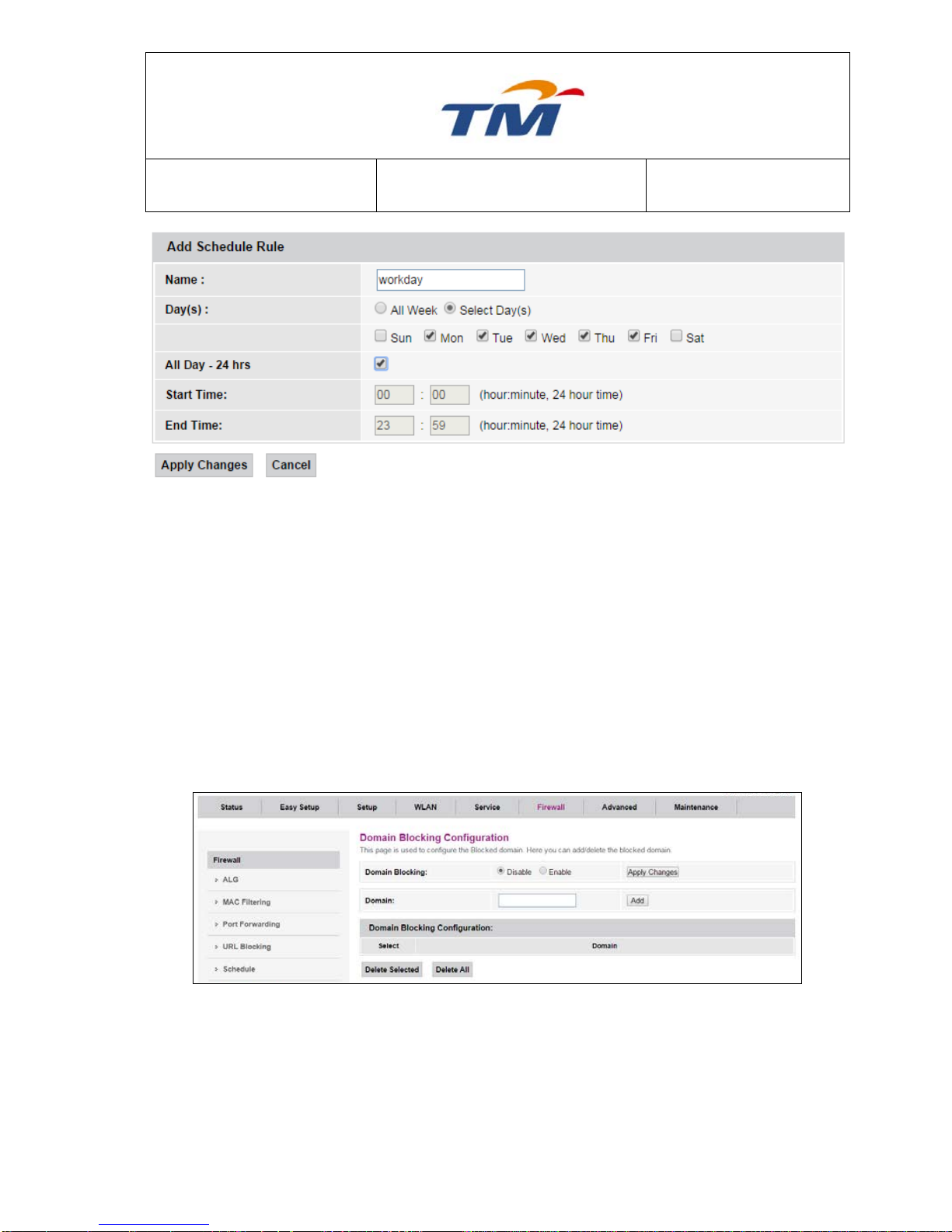
6.5.5 Schedule
Click Add at the bottom of the page and configure the parameters to add a schedule rule to be
applied for your firewall.
Page 47
SYSTEM TECHNOLOGY
Doc. No.:
ST/WI/RG/RGX4400
Revision No: 1.0
- 43 -
Name Title of the Schedule Rule.
Day(s) You can choose ―All Week‖ or ―Select Day(s)‖.
All Day-24 hrs All day.
Start Time
End Time If you don’t choose ―All day-24 hrs‖, you must key in the Start Time and the End
Time.
6.5.6 Domain Blocking
If you want to block LAN PC’s access to some unsuitable websites, then this is the right place to
be configured. Here, you can configure domains block with little effort.
Domain Blocking Enable or disable the Domain Blocking feature.
Domain The blocked domain. If the URL of Taiwan Yahoo website is
tw.yahoo.com, the domain can be yahoo.com.
Page 48

SYSTEM TECHNOLOGY
Doc. No.:
ST/WI/RG/RGX4400
Revision No: 1.0
- 44 -
6.5.7 DoS
If enable Dos, you can do some settings to prevent some kinds of DOS attack.
6.5.8 DMZ
DMZ (Demilitarized Zone), a special network zone that is different from the external network or the
internal network. The servers in DMZ, such as Web server and e-mail server, are allowed to be
accessed by those clients in the external network. The internal network is protected behind the
Trust Zone interface, and is not allowed any user to access. Therefore, the internal network and
the external network are separated, this meets user’s private demand.
Page 49

SYSTEM TECHNOLOGY
Doc. No.:
ST/WI/RG/RGX4400
Revision No: 1.0
- 45 -
DMZ Host Enable or disable the DMZ feature.
DMZ Host IP Address IP address of the local host. This feature lets a local host to be
exposed to the Internet.
6.5.9 IPv4/Port Filtering
Enable or disable IPv4 filter, set the security level and the filter mode. You can also add an IP filter
rule to the IP filter list.
Incoming Specify the default action on the WAN to LAN forwarding path.
Outgoing Specify the default action on the LAN to WAN forwarding path
Direction Can choose Incoming or Outgoing
Page 50

SYSTEM TECHNOLOGY
Doc. No.:
ST/WI/RG/RGX4400
Revision No: 1.0
- 46 -
Protocol There are 3 options available: TCP, UDP and ICMP
Rule Action Deny or allow traffic when matching this rule.
Source IP Address The source IP address assigned to the traffic on which filtering is
Applied.
Subnet Mask Subnet-mask of the source IP
Port Starting and ending source port numbers.
Destination IP Address The destination IP address assigned to the traffic on which filtering is
applied.
Subnet Mask Subnet-mask of the destination IP
Port Starting and ending destination port numbers
6.5.9 IPv6/Port Filtering
Enable or disable IPv6 filter, set the security level and the filter mode. You can also add an IP filter
rule to the IP filter list.
Incoming Specify the default action on the WAN to LAN forwarding path.
Outgoing Specify the default action on the LAN to WAN forwarding path
Direction Can choose Incoming or Outgoing
Protocol There are 3 options available: TCP, UDP and ICMPv6
Rule Action Deny or allow traffic when matching this rule.
Source IP Address The source IP address assigned to the traffic on which filtering is
applied
Source Prefix Length The length of the source IP address prefix.
Page 51

SYSTEM TECHNOLOGY
Doc. No.:
ST/WI/RG/RGX4400
Revision No: 1.0
- 47 -
Destination IP Address The destination IP address assigned to the traffic on which filtering is
applied.
Destination Prefix Length The length of the Destination IP address prefix.
Source Port Starting and ending source port numbers.
6.6 Advanced Configuration
6.6.1 Static route
Static routing is a form of routing entry which is configured by user or system administrator
manually. On the contrary, dynamic routing is produced by a dynamic routing protocol.
Enable
Enable or disable static routing on the connection.
Destination IP
The network IP address of the subnet. The destination IP
can be specified as the IP address of a subnet or a specific
host in the subnet. It can also be specified as all zeros to
indicate that this route entry should be used for all
destinations when no other route entry is matched (this
Page 52

SYSTEM TECHNOLOGY
Doc. No.:
ST/WI/RG/RGX4400
Revision No: 1.0
- 48 -
route entry is the default gateway).
Mask
The network mask of the destination subnet. The default
gateway uses 0.0.0.0.
Next Hop
The IP address of the next hop through which the traffic will
flow towards the destination subnet.
Metrics
Defines the number of hops between network nodes that
data packets travel. The default value is 0, which means
that the subnet is directly connected with the local LAN
network.
Interface
The WAN interface to which a static routing subnet is to be
applied
Add Route Add a user-defined destination route.
Update Update the selected destination route on the Static Route
Table.
Delete Selected Delete a selected destination route on the Static Route Table
Show Routes Click this button to view the device’s routing table. The IP
Route Table displays in following Figure.
6.6.2 SNMP
Simple Network Management Protocol (SNMP) is a popular protocol for network management. It is
used for collecting information from network devices and configuring network devices. The network
devices include servers, printers, hubs, switches, and routers on an Internet Protocol (IP) network.
Page 53

SYSTEM TECHNOLOGY
Doc. No.:
ST/WI/RG/RGX4400
Revision No: 1.0
- 49 -
System Description System description for the device.
System Contact Contact person and/or contact information for the device.
System Name An administratively assigned name for the device.
System Location The physical location of the device.
System Object ID Vendor object identifier. It’s the vendor’s authoritative
identification of the network management subsystem
Trap IP Address Destination IP address of the SNMP trap.
Community name (read-only) Name of the read-only community. This read-only
community allows read operation to all objects in the
MIB.
Community name (write-only) Name of the write-only community. This write-only
community allows write operation to the objects defines
as read-writable in the MIB.
6.6.3 Remote Access
Select a connection, select one or more services and configure the source IP Range of each
selected services. The protocol, destination port, and default mapping port are displayed
automatically.
Page 54

SYSTEM TECHNOLOGY
Doc. No.:
ST/WI/RG/RGX4400
Revision No: 1.0
- 50 -
Service Name The service names you can choose: TELNET , FTP , TFTP , HTTP ,
HTTPS , SNMP , SSH , PING , TR069.
LAN Check/un-check the services on the LAN column to allow/un-allow the
services access from LAN side;
WAN Check/un-check the services on the WAN column to allow/un-allow
the services access from WAN side.
WAN Port This field allows the user to specify the port of the corresponding
service.
6.6.4 IP UNNumber
After enable IP UNNumber function, you can select a WAN connection, set the IP address, specify
the start and end addresses from the address pool for IP unnumber assignment. You can also set
port binding.
Page 55

SYSTEM TECHNOLOGY
Doc. No.:
ST/WI/RG/RGX4400
Revision No: 1.0
- 51 -
Enable IP UNNumber Enable or disable static routing on the connection.
WAN Connection The WAN interface which will set with IP UNNumber.
IP Address Key in the IP Address provided by your Internet Service
Provider.
MASK Key in the mask provided by your Internet Service Provider.
Start Address Key in the Start Address which is the same IP address prefix
with IP Address.
End Address Key in the End Address which is the same IP address prefix
with IP Address.
Port Binding Can set the port binding with the wan connection.
6.6.5 QoS
QoS (Quality of Service) is designed to provide a better service for the specified network
communication. User can use QoS function to limit total bandwidth and set QoS mode. If choose
user customized mode, you can edit QoS rules in QoS Classification page.
Page 56

SYSTEM TECHNOLOGY
Doc. No.:
ST/WI/RG/RGX4400
Revision No: 1.0
- 52 -
The RG device supports the following modes: Fair Competition, Game First, Download First, Web
First and User Customized. If you choose Game First, you will see that the priority of Game
service is high, the priority of download is low and the priority of web access is middle in the QoS
Scheduling Rule Table.
Upload Bandwidth The upload Bandwidth of the Internet
Download Bandwidth The download Bandwidth of the Internet.
6.6.6 QoS Classification
Most QoS tools classify traffic, so different classes of traffics will be treated differently. You can
use this method to prioritize one type of traffic over another.
Page 57

SYSTEM TECHNOLOGY
Doc. No.:
ST/WI/RG/RGX4400
Revision No: 1.0
- 53 -
If you choose the user customized mode of the 6.6.5 .
You should set the Upload Bandwidth and Download Bandwidth first. Next, you can choose the
service name, and then you must key in the Source IP and Destination Port, choose the protocol
and set the priority. After you click ―Add‖, there is one rule in the Table. At last, you should click
―Apply Changes‖ after confirm.
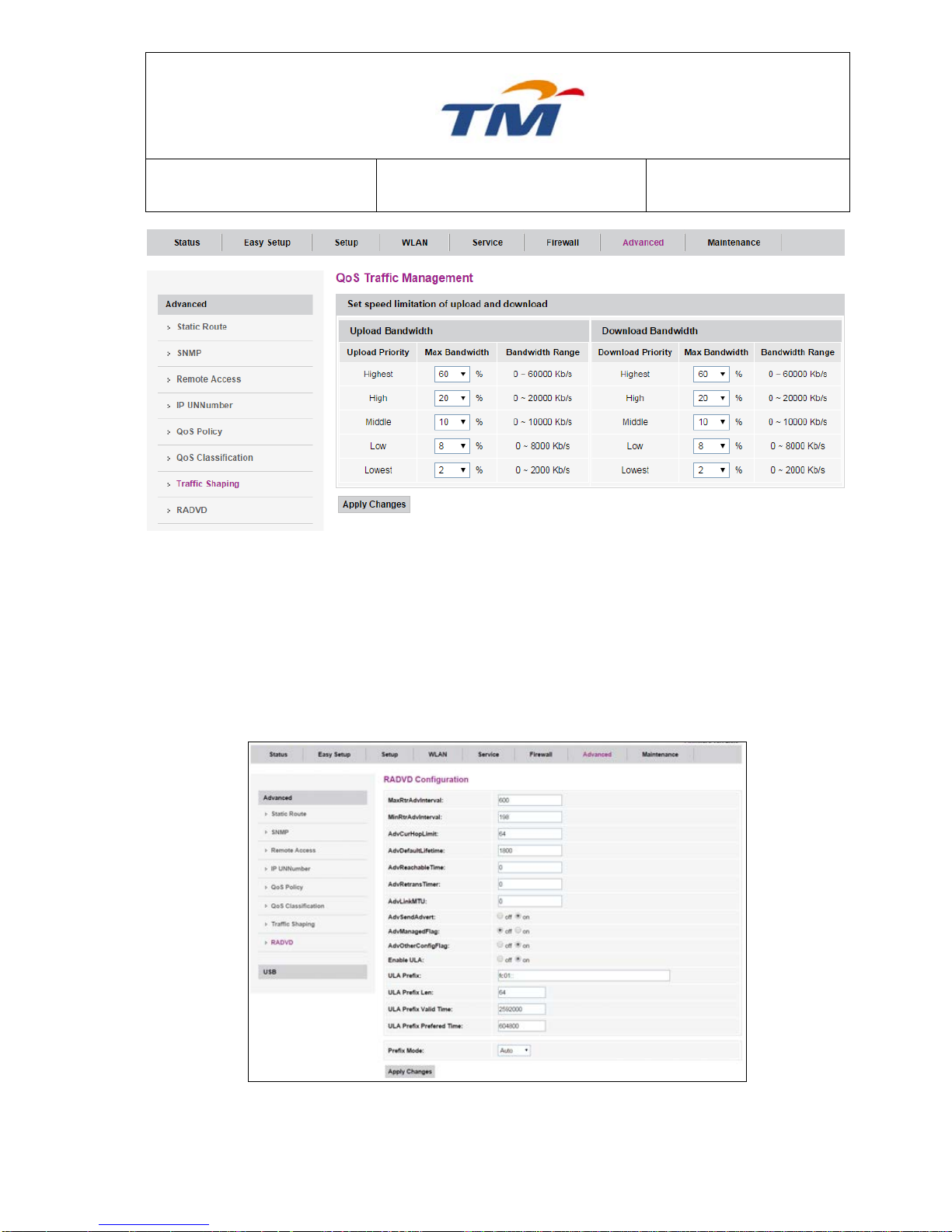
6.6.7 Traffic Shaping
QoS Traffic Management is used to set the specific percent of the Upload Bandwidth & Download
Bandwidth according to the specific priority.
Page 58
SYSTEM TECHNOLOGY
Doc. No.:
ST/WI/RG/RGX4400
Revision No: 1.0
- 54 -
6.6.8 RADVD
The Router Advertisement Daemon (radvd) is an open-source software product that implements
link-local advertisements of IPv6 router addresses and IPv6 routing prefixes using the Neighbor
Discovery Protocol (NDP) as specified in RFC 2461. With these advertisements, hosts can
automatically configure their addresses and some other parameters. They also can choose a
default router based on these advertisements.
Page 59

SYSTEM TECHNOLOGY
Doc. No.:
ST/WI/RG/RGX4400
Revision No: 1.0
- 55 -
6.6.9 Print Server
Printer Server is a device that connects printers to client computers via a network. It accepts print
jobs from the computers and sends the print jobs to the appropriate printers. It can even queues
the jobs locally to accommodate the fact that jobs may arrive more quickly than the printer can
actually handle.
6.6.10 FTP Server
An FTP server is running on the device, so you can do the files exchange with the USB mass
storage device through FTP application.
First, the USB disk should be inserted into the USB interface. System can show the USB status.
Key in the FTP Server Port and enable the FTP Server, click ―Submit‖. Key in the FTP Server
Account Manager’s User Name and Password, and then, choose the Manager’s Rights and click
―Apply Changes‖.
Page 60

SYSTEM TECHNOLOGY
Doc. No.:
ST/WI/RG/RGX4400
Revision No: 1.0
- 56 -
You can use the File Explorer to access the FTP server, and the address should be
―ftp://192.168.0.1‖, after press ENTER on keyboard, you can get all files on the USB disk, and
upload or download the file from it.
6.6.11 Download Master
This function is used to set remote FTP download.
Page 61

SYSTEM TECHNOLOGY
Doc. No.:
ST/WI/RG/RGX4400
Revision No: 1.0
- 57 -
USB Download Directory Choose the USB disk to which you want to download files.
User Name The user name to access the FTP Server.
Password The password to access the FTP Server.
Port The port to access the FTP Server, default is 21.
Remote URL The URL of the FTP server.
6.6.12 Download Master BiT
This page is used to perform remote BiT Torrent download.
BiT Download Directory Choose the USB disk to which you want to download files.
Upspeed Limit Set the MAX upload speed
Downspeed Limit Set the MAX download speed
Bit Seed Choose the Bit seed which you want to download.
Page 62

SYSTEM TECHNOLOGY
Doc. No.:
ST/WI/RG/RGX4400
Revision No: 1.0
- 58 -
BT Seed Upload the Bit seed file to the Device.
Status Here shows the download status when you start to download.
6.7. Maintenance
6.7.1 Reset/Reboot
Whenever, you can use this Web configuration to change system’s settings. These settings are
initially placed in temporary storage. They will be lost if the device is reset or turn off. To save your
settings for future use, you can use the commit function. Here you can also reset the current
settings to the default settings.
6.7.2 Backup/Restore
Backup button performs backup for previous configuration of RG, and click Restore Button will
restore the configuration from file that saved before.
Page 63

SYSTEM TECHNOLOGY
Doc. No.:
ST/WI/RG/RGX4400
Revision No: 1.0
- 59 -
6.7.3 System Log
A log file is a file that records either the events which happen while an operating system or other
software runs, or the personal messages between different users of a communication software.
6.7.4 Password
To set the new password for all the web server interfaces.
User Name Select user.
Old Password Key in the old password for this selected login.
New Password Key in the new password here.
Confirmed Password Key in the new password here again to confirm.
Page 64

SYSTEM TECHNOLOGY
Doc. No.:
ST/WI/RG/RGX4400
Revision No: 1.0
- 60 -
6.7.5 Firmware Upgrade
To upgrade the firmware for the RG device
Click the Choose File button to select the firmware file.
Confirm your selection.
Click the Upgrade button to start upgrading.
IMPORTANT! Do not turn off your RG device while this procedure is in progress.
6.7.6 ACL
This page is used to configure the IP Address for Access Control List. If ACL is enabled, only the
IP address in the ACL Table can access CPE. Here you can add/delete the IP Address.
Enable Enable/disable the ACL function
Interface Select the interface domain: LAN or WAN
IP Address Key in the IP address that allow access to this device
Subnet Mask Key in the Subnet Mask of the IP Address
Page 65

SYSTEM TECHNOLOGY
Doc. No.:
ST/WI/RG/RGX4400
Revision No: 1.0
- 61 -
6.7.7 Time Zone
Simple Network Timing Protocol (SNTP) is a protocol which is used to synchronize the system
time to the public SNTP servers. The RG device supports SNTP client functionality in compliance
with IETF RFC2030. SNTP client runs in daemon mode. For configuring the system clock in the
RG device, SNTP client sends client requests to the configured SNTP server periodically.
Current Time The current time of the specified time zone. You can set the
current time by yourself or configured by SNTP.
Time Zone Select The time zone in which the RG device resides.
Enable SNTP client update Enable the SNTP client to update the system clock.
SNTP server The IP address or the host name of the SNTP server. You can
select from the list or set it manually.
6.7.8 TR-069
This page is to enable or disable TR069 Setting. TR069 is used to manage the RG device from the
remote internet side.
Page 66

SYSTEM TECHNOLOGY
Doc. No.:
ST/WI/RG/RGX4400
Revision No: 1.0
- 62 -
TR069 Enable or Disable the TR069 function.
URL ACS URL.
User Name The username the RG device should use when connecting to the ACS.
Password The password the RG device should use when connecting to the ACS.
Periodic Inform When this field is enabled, the RG device will send an Inform RPC to
the ACS server at the system startup, and will continue to send it
periodically at an interval time. Periodic Inform Interval field defines
the period; When this field is disabled, the RG device will only send
Inform RPC to the ACS server once at the system startup.
Interval Time interval in second to send Inform RPC.
Connection Request
User Name The username the remote ACS should use when connecting to this
device.
Password The password the remote ACS should use when connecting to this
device.
6.7.9 Ping & Ping6
Once you have configured your RG device, it is a good idea to make sure you can ping the
network. A ping command sends a message to the host you specify. If the host receives the
message, it will send messages in reply. To use it, you must know the IP address of the host you
are trying to communicate with and enter the IP address in the Host Address field. Click Go! to
start the ping command, the ping result will then be shown in this page.
Page 67

SYSTEM TECHNOLOGY
Doc. No.:
ST/WI/RG/RGX4400
Revision No: 1.0
- 63 -
Host Address The IP address you want to ping.
6.7.10 Tracert & Tracert6
Traceroute Diagnostics is used to find the route between your wireless router and the host on the
Internet. The diagnostic result will be displayed after you key in Host IP address and click ―GO!‖.
Host Address The IP address you want to traceroute.
Page 68

SYSTEM TECHNOLOGY
Doc. No.:
ST/WI/RG/RGX4400
Revision No: 1.0
- 64 -
6.8. Status
The submenus of status contain Device Info, IPv6, WLAN Status of 2.4 GHz & 5 GHz, Interface
Statistic, USB Status, and ARP Table.
6.8.1 Device Status
This page shows all the information of Router, including the WAN Connection status.
6.8.2 IPv6
This page displays the information of all IPv6 Local IP, including the IPv6 IP of the Router in WAN
side.
Page 69

SYSTEM TECHNOLOGY
Doc. No.:
ST/WI/RG/RGX4400
Revision No: 1.0
- 65 -
6.8.3 WLAN Status of 2.4 GHz
This page displays the status information of wireless connection ( 2.4 GHz ), including the Mode,
Bans, SSID, Channel Number, Encryption type, Associated Clients & Active WLAN Clients.
6.8.4 WLAN Status of 5 GHz
This page displays the status information of wireless connection ( 5 GHz ), including the Mode,
Bans, SSID, Channel Number, Encryption type, Associated Clients & Active WLAN Clients.
.
Page 70
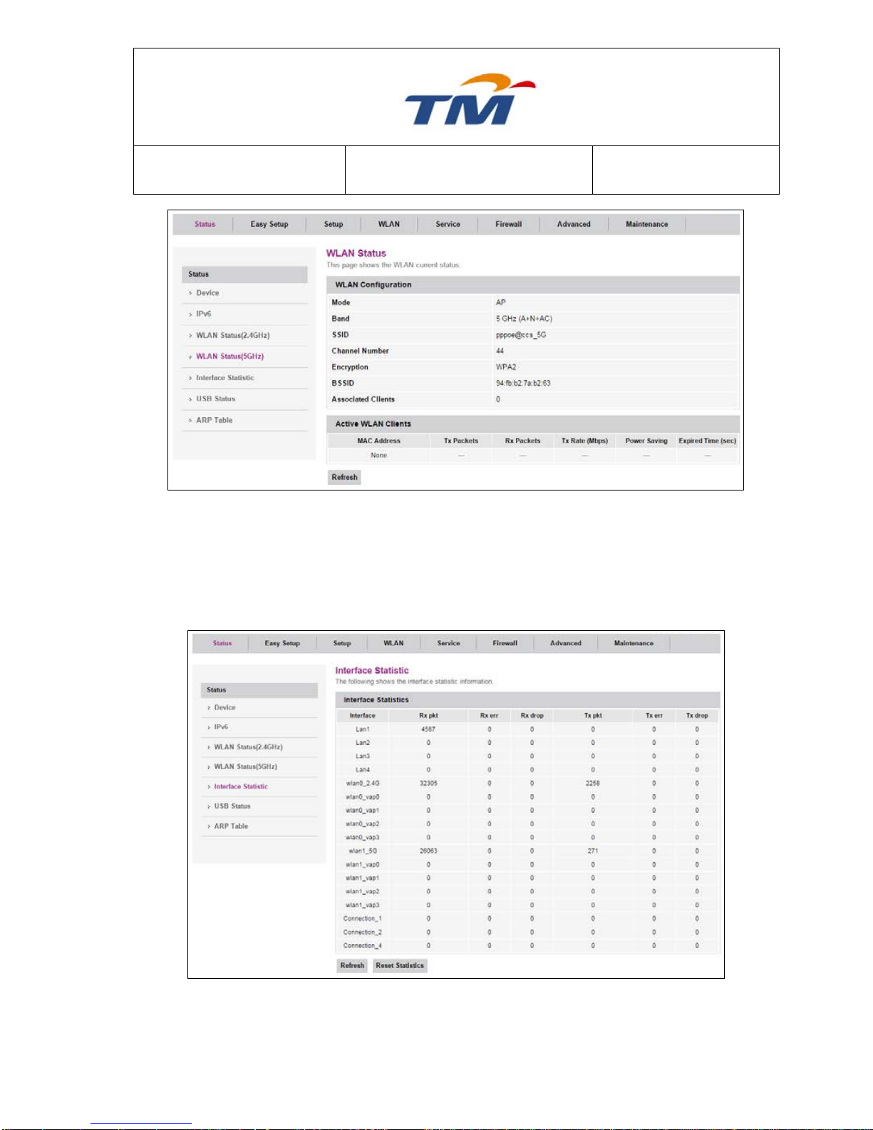
SYSTEM TECHNOLOGY
Doc. No.:
ST/WI/RG/RGX4400
Revision No: 1.0
- 66 -
6.8.5 Interface Statistic
This page displays the LAN & WLAN statistical information, including the bytes and quantities of
sent and received packets.
Page 71

SYSTEM TECHNOLOGY
Doc. No.:
ST/WI/RG/RGX4400
Revision No: 1.0
- 67 -
6.8.6 USB Status
This page displays the information of the USB device connected to the router.
6.8.7 ARP Table
This page displays the information of the client’s IP address and the Mac Address which
connected to Router.
Page 72

SYSTEM TECHNOLOGY
Doc. No.:
ST/WI/RG/RGX4400
Revision No: 1.0
- 68 -
7.0. Configuring the IP Address in Windows XP
The following describes the procedure for configuring the IP address on a PC of Windows XP:
Step1 Right-click the icon of My Network Places and
choose Properties in the menu. The Network
Connections page appears.
Step2 Right click the network adapter icon and select
Properties in the menu. The Local Area
Connections Properties appears. (Note: if you
have several network cards, it may not display the
Local Area Connections Properties page. It may
display other dialog boxes.)
Step3 Double-click the Internet Protocol (TCP/IP), and
the Internet protocol (TCP/IP) Properties page
appears.
Page 73

SYSTEM TECHNOLOGY
Doc. No.:
ST/WI/RG/RGX4400
Revision No: 1.0
- 69 -
Step4 Select Use the following IP address and enter
the IP address of the network adapter. The IP
address should belong to the IP pool
192.168.0.X (X is a number from 2 to 254).
Step5 Ping the default IP address of the
WIRELESS ROUTER. If the left page
appears, the network connection of
your wireless router is normal.
Page 74

SYSTEM TECHNOLOGY
Doc. No.:
ST/WI/RG/RGX4400
Revision No: 1.0
- 70 -
8.0. Troubleshooting
1. All indicators are off
Check the connection between the power adapter and the power socket.
Check whether the power switch is turned on.
2. Failure to login to the wireless router
Check the connection between the computer and the wireless router, the steps as shown
below:
(1) Choose Start > Run from the desktop and enter ping 192.168.0.1 (IP address of the
wireless router) in the DOS window.
(2) If the wireless router cannot be accessed, check the following:
The type of the network cable.
The connection between the wireless router and the computer.
The TCP/IP setting of your computer.
3. To restore the factory defaults after incorrect configuration
Press the Reset button for about 10 seconds to load the default configuration.
The default IP address and subnet mask of the device are 192.168.0.1 and 255.255.255.0
respectively. The user name and the password are admin and admin respectively.
4. Failure to access the Web configuration page of the wireless router
Step1 Run the Web browser (for example, IE) and choose Tools > Internet Options.
Step2 Click Delete Cookies and then Delete Files in the Temporary Internet files pane.
5. Failure to establish the network connection
The following table describes the possible causes and the corresponding solutions:
Page 75

SYSTEM TECHNOLOGY
Doc. No.:
ST/WI/RG/RGX4400
Revision No: 1.0
- 71 -
Fault Cause
Solution
Beyond the wireless
coverage
(1) Place the wireless router near the client.
(2) Modify the channel setting.
Authentication problem
(1) Use the cable to connect computer to the device.
(2) Check the network security settings.
(3) Press the Reset button to reset the device.
Failure to find the device
(1) Try to reset the wireless router and test the
device again.
(2) Check the setting of the wireless network adapter.
(3) Check the SSID and the encryption settings.
6. Failure to access the Internet through wireless connection with the wireless router
(1) Place the device to the wireless-enabled area where you can access the Internet.
(2) Check whether the wireless network adapter can connect to corresponding station.
(3) Check whether the wireless channel accords with the channel of your country or
zone.
(4) Check the encryption settings.
(5) Check whether the cable is connected to the correct interface.
(6) Replace a network cable to connect the wireless router.
7. Failure to access the Internet
(1) Check whether the status of each LED
indicator on the network device connected
to the wireless router is normal.
(2) Check whether the WAN indicator is on. If
the WAN indicator is off, please check
whether the cable connected to the WAN
interface is loose.
(3) Check whether the Internet indicator is
always white. If the Internet indicator keeps
on in white without blinking, the wireless
router has successfully accessed the
Internet.
(4) Reboot your computer.
(5) Set the device again.
(6) Check whether the WAN indicator is on.
(7) Check the encryption settings of wireless
network.
(8) Check whether the PC that connects to the
device can obtain the IP address through
the wireless network or the cable network.
(9) Check the LAN settings of your Internet
options, and do not use a proxy server for
your LAN. See the figure on the left.
Page 76

SYSTEM TECHNOLOGY
Doc. No.:
ST/WI/RG/RGX4400
Revision No: 1.0
- 72 -
9.0. Networking Basics
9.1. Check Your IP Address
After you install your TRG212M wireless router, by default, the TCP/IP settings should be set to
obtain an IP address from a DHCP server automatically. To verify your IP address, please follow
the steps below.
Choose Start
>
Run. In the run box type cmd and click OK.
At the prompt, type ipconfig and press Enter.
This will display the IP address, subnet mask and the default gateway of your adapter.
If the address is 0.0.0.0, check your adapter installation, security settings and the settings on your
wireless router. Some firewall software programs may block a DHCP request on newly installed
adapters.
If you are connecting to a wireless network at a hotspot, please contact an employee or
administrator to verify their wireless network settings.
9.2. Statically Assigning an IP Address
Page 77

SYSTEM TECHNOLOGY
Doc. No.:
ST/WI/RG/RGX4400
Revision No: 1.0
- 73 -
If you are not using a DHCP capable gateway/wireless router, or you need to assign a static IP
address, please follow the steps below:
Step 1
Windows® XP - Choose Start > Control Panel > Network Connections
from the desktop.
Windows® 2000 - Right-click My Network Places from the desktop and choose Properties.
Step 2
Right-click Local Area Connection of your network adapter and choose Properties.
Step 3
Select Internet Protocol (TCP/IP) and click Properties.
Step 4
Click Use the following IP address and enter an IP address that is on the same subnet as your
network or the LAN IP address on your wireless router.
Example: If the wireless router’s LAN IP address is 192.168.0.1, make your IP address
192.168.0.X (X is a number between 2 and 254). Make sure that the number you choose is not in
use on the network. Set the Default Gateway to be the same as the LAN IP address of your
wireless router (192.168.0.1). Set the Primary DNS to be the same as the LAN IP address of your
wireless router (192.168.0.1). The Secondary DNS is not needed or you may enter a DNS server
from your ISP.
Step 5
Click OK twice to save your settings.
Page 78

SYSTEM TECHNOLOGY
Doc. No.:
ST/WI/RG/RGX4400
Revision No: 1.0
- 74 -
10.0. Technical Specifications
SDRAM/Serial
Flash
128MB/32MB
Standards
IEEE 802.11b/g/n 2.4GHz
IEEE 802.11a/n/ac 5GHz
Wireless
Frequency Range
2.4~2.4835 GHz 5.15~5.85 GHz
Wireless
Transmission
Power (MAX)
11n: 22 dBm
11g: 23 dBm
11b: 24 dBm
Antenna
4 x 3 dBi Built-in antenna
Protocol
RFC768 UDP, RFC791 IP, RFC792 ICMP, FC793 TCP, RFC826
ARP, RFC2516 PPPoE, RFC2131 DHCP, ALG
Interface
1 x 10/100M Auto MDI/MDIX WAN port
4 x 10/100M Auto MDI/MDIX LAN ports
1 x 2.0 USB ports
1 x 3.0 USB ports
Wireless Security
64/128-bit WEP, WPA/WPA2, WPA-PSK/WPA2-PSK data security
and TKIP/AES encryption.
LED Indicators
1 x WAN, 1 x INTERNET, 1 x 5GHz, 1 x 2.4GHz, 4 x LAN, 1 x PWR
Environment
Operating Temperature: 0°C~55°C
Storage Temperature: 40°C~85°C
Operating Humidity: 10%~95%, non-condensing
Storage Humidity: 5%~95%, non-condensing
Power Supply
Input: 100~240 V AC, 50/60 Hz
Output: 12 V DC, 2.0A
Dimension
L*W*H: 180 * 180 * 34.5 mm
Weight
500 g
 Loading...