

TLV VS1C Instruction Manual

g
r
r
g
lish
En
Thank you for purchasing the Automatic Air Vent.
This product has been thoroughly inspected before being
shipped from the factory. When the product is delivered,
before doing anything else, check the specifications and
external appearance to make sure nothing is out of the
ordinary. Before beginning installation or maintenance,
please read this manual to ensure correct usage of the
product.
This air vent is for the discharge of air from watercarrying pipes. It must not be used for the discharge of
air from steam spaces.
If there is a rapid rise in liquid level (caused by rapidly opening a shut-off valve, etc.), a
small amount of liquid may leak with discharged air immediately before the vent closes.
This instruction manual is needed not only for installation, but for subsequent
troubleshooting. Please keep it in a safe place for future reference.
The contents of this manual are subject to change without notice.
1. Safety Considerations
WARNING
CAUTION
CAUTION
CAUTION
CAUTION
CAUTION
CAUTION
CAUTION
2. Specifications
Refer to the product nameplate for detailed specifications.
Nominal Diamete
Maximum Allowable Pressure*
Max. Allowable Temperature*
Maximum Differential Pressure
Max. Operating Temperature
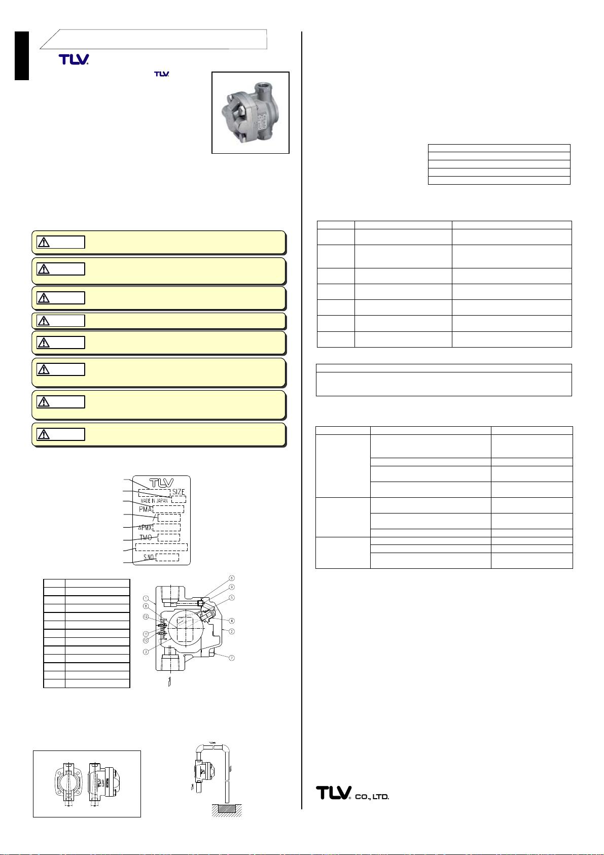
3. Configuration
No. Name
1 Body
2 Cover
3 Float
4 Valve Seat
5 Valve Seat Gasket
6 Cover Gasket
7 Cover Bolt
8 Nameplate
9 Connector
10 Screw
11 Spring Washer
12 Guide Plate
4. Proper Installation
1. Before installation, be sure to remove all protective seals.
2. Before installing the product, open the inlet valve and blow out the piping to remove
any piping scraps, dirt and oil. Close the inlet valve after blowdown.
3. This product must be installed vertically, with the inlet at the bottom and the outlet at
the top, and should be inclined within 5° horizontally and front-to-back as shown right
(Figure 1).
Tolerance Angle for Installation
5° 5° 5° 5°
Automatic Air Vent VS1C
NEVER apply direct heat to the float. The float may explode due to
increased internal pressure, causing acciden ts lea ding to serious injury
or damage to property and equipment.
Install properly and DO NOT use this product outside the recommended
operating pressure, temperature and other specification ranges.
Improper use may result in such hazards as damage to the product or
malfunctions which may lead to serious acc id en ts. Local regulations
may restrict the use of this product to below the conditions quoted.
Use only under conditions in which no freeze-up will occur. Freezing
may damage the product, leading to fluid discharge, which may cause
burns or other injury.
DO NOT use this product in excess of the maximum operating pressure
differential; such use could make discharge impossible (blocked).
Take measures to prevent people from coming into direct contact with
product outlets. Failure to do so may result in burns or other injury from
the discharge of fluids.
Be sure to use only the recommended components when repairing the
product, and NEVER attempt to modify the product in any way. Failure to
observe these precautions may result in damage to the product or burns
or other injury due to malfunction or the discharge of fluids.
When disassembling or removing the product, wait until the internal
pressure equals atmospheric pressure and the surface of the product
has cooled to room temperature. Disassembling or removing the
product when it is hot or under pressure may lead to discharge of fluids,
causing burns, other injuries or damage.
Installation, inspection, maintenance, repairs, disassembly, adjustment and
valve openin
personnel.
/closing should be carried out only by trained maintenance
Model
Valve No.**
Serial Numbe
Figure 1 Figure 2
* Maximum allowable pressure
(PMA) and maximum
allowable temperature (TMA)
are PRESSURE SHELL
DESIGN CONDITIONS (NOT
OPERATING CONDITIONS)
** Valve No. is displayed for
products with options. This
item is omitted from the
nameplate when there are no
options.
Do not use for toxic, flammable
or otherwise hazardous fluids.
For intended use only
INSTRUCTION MANUAL
4. Install the product in a location where air is likely to collect, such as a bend in the
piping.
5. Install outlet piping leading to a drainage vessel or ditch. Make sure the end of the
pipe is above the waterline, so that dirt and water can not be sucked up by vacuum
when the system shuts down (Figure 2).
6. A valve and screen (40 mesh or finer) must be installed before the product inlet.
5. Inspection and Maintenance
Operational Check: Visual inspections should be carried out on a daily basis to
determine whether the air vent is operating properly or has failed. Periodically (at least
biannually) the operation should also be checked.
If the air vent should fail, it may cause damage to piping and equipment, resulting in
faulty or low quality product
manufacture.
When parts have been
removed, or during periodic
inspections, use the table
right to inspect the parts and
replace any that are found to
be defective.
6. Disassembly / Reassembly
Use the following procedures to remove components. Use the same procedures in
reverse to reassemble. If drawings or other special documentation were supplied for the
product, any torque given there takes precedence over values shown here.
Part During Disassembly During Reassembly
Cover Bolt Remove with a 17 mm (
Cover Remove carefully; take care to prevent
Float Remove, being careful not to scratch
wrench
any damage to the float, which may fall
out when the cover is removed
the polished surface
Gaskets: check for warping or damage
Valve Seat Surface: check for damage or wear
Float: check for deformation, damage or fluid inside
Plate: check for deformation or damage
11
⁄
”) socket
16
Procedure
Coat threads with anti-seize and
tighten to 45 N⋅m (33 lbf⋅ft)
Make sure the sealing surfaces
are clean, then reattach; be
careful not to bend the float guides
Place inside the body being
careful not to scratch or misshape
Connector Remove Insert into hole in cover
Cover
Gasket
Valve Seat Remove with a 13 mm (
Valve Seat
Gasket
Note: Do not change the position of the float guides. Tight sealing 1 N⋅m ≈10 kg⋅cm
cannot be guaranteed if the float guides have been moved out of position.
Body Interior Plate (part No. 12)
The guide plate built into the body with screws (and spring washers) does not
require removal during normal product disassembly. The plate should only be
replaced when it has become deformed or damaged. Upon reassembly, tighten to
0.3 N⋅m (0.2 lbf·ft) with a Phillips screwdriver.
Remove if damaged Replace with a new gasket if
1
⁄
”) socket
wrench
Remove gasket and clean sealing
surfaces
2
warped or damaged
Coat threads with anti-seize and
tighten to 15 N⋅m (11 lbf⋅ft)
Replace with a new gasket if
warped or damaged
7. Troubleshooting
When the air vent fails to operate properly, use the following table to locate the cause.
Problem Cause Remedy
No air is
discharged
or
discharge
is poor
Liquid
leaks when
vent is
closed
Vent does
not close
and liquid
spurts out
Air is not reaching the vent because the liquid
in the piping is not being displaced by air
Valve seat is clogged Clean the valve seat
Inlet or outlet piping is clogged Clean piping or any
Operating pressure exceeds the rated
maximum operating pressure
Valve seat is damaged or clogged with dirt or
scale
Float is deformed, dirty or coated with a film Clean or replace float
Improper installation Correct the installation
Liquid is inside the float Replace with new float
Plate is damaged Replace with new plate
Specific gravity of the liquid is not suitable for
this product
Correct the inlet piping
(Inner diameter should be
at least 16 mm [
upstream strainer
Replace with product of
suitable operating pressure
Clean or replace with new
valve seat
Consult TLV
8. Product Warranty
1. Warranty Period: One year following product delivery.
2. TLV CO., LTD. warrants this product to the original purchaser to be free from
defective materials and workmanship. Under this warranty, the product will be
repaired or replaced at our option, without charge for parts or labor.
3. This product warranty will not apply to cosmetic defects, nor to any product whose
exterior has been damaged or defaced; nor does it apply in the following cases:
1) Malfunctions due to improper installation, use, ha ndling, etc., by other than TLV
CO., LTD. authorized service representatives.
2) Malfunctions due to dirt, scale, rust, etc.
3) Malfunctions due to improper disassembly and reassembly, or inadequate
inspection and maintenance by other than TLV CO., LTD. authorized service
representatives.
4) Malfunctions due to disasters or forces of nature.
5) Accidents or malfunctions due to any other cause beyond the control of TLV CO., LTD.
4. Under no circumstances will TLV CO., LTD. be liable for consequential economic
loss or damage or consequential damage to property.
For Service or Technical Assistance:
Contact your TLV representative or your regional TLV office.
United Kingdom: [44]-(0)1242-227223 France: [33]-(0)4-72482222
Germany & Other European Countries: [49]-(0)7263-9150-0
North America: [1]-704-597-9070 Argentina: [54]-(0)11-5197-7274
China: [86]-21-6482-8622 Australia: [61]-(0)3-9873-5610
Korea: [82]-(0)31-726-2105
Other East Asian Countries: [65]-6747-4600 Other Countries: [81]-(0)79-427-1818
Manufacturer:
Malaysia: [60]-3-5632-7988
881 Nagasuna, Noguchi, Kakogawa, 675-8511 Hyogo, Japan
Tel: [81]-(0)79-422-1122 Fax: [81]-(0)79-422-0112
1 N⋅m ≈10 kg⋅cm
5
/8"])
Rev. 7/2008 (T)
EINBAU-UND BETRIEBSANLEITUNG
V
V
V
V
V
V
V
r
r
k
A
Deutsch
Wir danken Ihnen für den Kauf des Entlüfters
VS1C.
Dieses Produkt wurde nach Fertigstellung sorgfältig
geprüft und verließ unsere Fabrik vollständig und
fehlerfrei. Wir empfehlen jedoch, nach Erhalt den
einwandfreien Zustand zu überprüfen und die
Spezifikation mit Ihren Bestellunterlagen zu vergleichen.
Bei Unstimmigkeiten, benachrichtigen Sie uns bitte
umgehend. Lesen Sie die Anleitung sorgfältig durch, um
den korrekten Gebrauch dieses Produkts sicherzustellen.
Dieser Entlüfter wird zum Entfernen von Luft aus
Wasserleitungen eingesetzt. Er darf nicht benutzt werden,
um Luft aus Dampfsystemen zu entfernen.
Bei einem raschen Anstieg des Flüssigkeitsspiegels (etwa durch schnelles Ö ffnen des
Absperrorgans) kann vor dem Schließen des Entlüfters eine geringe Menge Flüssigkeit
mit der Luft entweichen.
Diese Anleitung wird für den Einbau und später für Wartung und Reparatur benötigt.
Daher sollte sie an einer leicht zugänglichen Stelle aufbewahrt werden.
Änderungen dieser Einbau-und Betriebsanleitung vorbehalten.
1. Sicherheitshinweise
ARNUNG
W
ORSICHT
ORSICHT
ORSICHT
ORSICHT
ORSICHT
ORSICHT
ORSICHT
2. Technische Daten
Die Technischen Daten stehen auf dem Typenschild.
Maximal zulässiger Druck*
Maximal zulässige Temperatur*
Maximaler Differenzdruc
Maximale Betriebstemperatu
3. Aufbau
Nr. Bauteil
1 Gehäuse
2 Gehäusedeckel
3 Schwimmerkugel
4 Ventilsitz
5 Ventilsitzdichtung
6 Gehäusedichtung
7 Gehäuseschraube
8 Typenschild
9 Verbindungshülse
10 Schraube
11 Spannring
12 Führungsplatte
4. Einbauhinweise
1. Vor dem Einbau die Transport-Schutzkappen entfernen.
2. Vor dem Einbau das Einlassventil öffnen und die Leitung durchblasen, um Öl und
Verschmutzungen zu entfernen. Danach das Ventil schließen.
3. Dieses Produkt ist innerhalb der rechts gezeigten Schräglagentoleranzen vertikal
einzubauen, mit dem Einlass unten und dem Auslass oben (Abbildung 1).
Schräglagentoleranz
5° 5° 5° 5°
Automatischer Entlüfter VS1C
Die Schwimmerkugel darf NICHT ERHITZT werden, da sie infolge erhöhten
Innendruckes platzen kann, was schwere Unfälle und Verletzungen oder
Beschädigung von Anla g en zur Folge hat.
Die Einbauhinweise beachten und die spezifizierten Betriebsgrenzen
NICHT ÜBERSCHREITEN. Nichtbeachtung kann zu Betriebsstörungen oder
Unfällen führen. Lokale Vorschriften können zur Unterschreitung der
angegebenen Werte zwingen.
Nur in frostsicherer Umgebung einsetzen. Einfrieren kann das Produkt
beschädigen, was zu Verbrennungen oder Verletzungen durch
austretende Fluide führt.
Maximalen Differenzdruck nicht überschreiten, da sonst die Kondensatableitung unmöglich werde n ka nn (Block a ge )
In sicherer Entfernung von Auslassöffnungen aufhalten und andere
Personen warnen, sich fernzuhalten. Nichtbeachtung kann zu
Verletzungen durch austretende Fluide führen.
Zur Reparatur nur Original-Ersa tzteile verwend e n un d NI CHT V E RS UCHE N,
das Produkt zu verändern. Nichtbeachtung kann zu Beschädigungen
führen, die Betriebsstörungen, Verbrennungen oder andere Verletzungen
durch austretende Fluide verursachen.
Vor Öffnen des Gehäuses und Ausbau von Teilen warten, bis der Innendruck sich auf Atmosphärendruck gesenkt hat und das Gehäuse auf
Raumtemperatu r a b gekühlt ist. Nichtbeachtung k a nn zu Verbrennungen
oder Verletzungen durch austretende Fluide führen.
Arbeiten an Rohrleitungen, Einbau und Ausbau von Teilen, Inspektion,
Öffnen/Schließen und Einstellung von Armaturen dürfen nur von
geschultem Personal vorgenommen werden.
Typ
Größe/DN
Ventil-Nr.**
Seriennumme
bbildung 1 Abbildung 2
* Maximal zulässiger Druck
(PMA) und maximal
zulässige Temperatur (TMA)
sind AUSLEGUNGSDATEN
NICHT BETRIEBSDATEN.
** Die Ventil-Nr. wird angege-
ben bei Typen mit Optionen.
Bei Typen ohne Optionen
bleibt diese Stelle frei.
Nicht für giftige, entflammbare oder
sonst wie gefährliche Fluide
benutzen.
Nicht zweckentfremdet einsetzen!
4. Das Produkt dort einbauen, wo Luftansammlung erwartet wird, z. B. in einem Rohrkrümmer.
5. Die Austrittsleitung in eine Abwasserrinne oder -grube führen. Das Ende der Austrittsleitung darf nicht in Wasser eintauchen, da sonst bei Betriebsunterbrechungen
Wasser und Schmutz eingesaugt werden kann (Abbildung 2).
6. Am Einlass eine Absperrarmatur und einen Schmutzfänger (40 mesh oder feiner)
einbauen.
5. Inspektion und Wartung
Funktionsprüfung: Visuelle Inspek tionen sollten täglich erfolgen, um festzustelle n, ob
der Entlüfter ordnungsgemäß arbeitet, oder beschädigt ist.
Fehlerhafte Entlüfter können Beschädigungen an Rohrleitungen und Anlagen verur-
sachen, was zur Verschlechterung der Produktqualität führen kann.
Wenn Fehler entdeckt wurden,
überprüfen Sie die Teile entsprechend der Tabelle rechts und
ersetzen Sie die fehlerhaften
Teile.
6. Ausbau / Einbau
Den Ausbau von Teilen in dieser Reihenfolge vornehmen, d en Einbau in umgekehrter.
Falls Zeichnungen oder andere spezielle Dokumente mit dem Produkt geliefert wurden,
haben Angaben über Anzugsmomente in diesen Unterlagen Vorrang vor den hier
gezeigten Anzugsmomenten.
Überprüfung der Einzelteile
Dichtungen: auf Verformung oder Kratzer
Ventilsitzfläche: auf Kratzer oder Abnutzung
Schwimmerkugel: auf Verformung oder Kratzer
Führungsplatte: auf Verformung/ Beschädigung
Bauteil Bauteil Ausbau
Gehäuseschraube
Gehäusedeckel
Schwimmerkugel
Verbindungshülse
Gehäusedichtung
Ventilsitz Mit 13 mm Steckschlüssel
Ventilsitzdichtung
Vorsicht: Die Kugelauflagen nicht verstellen. Dichter Abschluss kann sonst nicht
Führungsplatte (Bauteil Nr. 12)
Die Schwimmerführungsplatte im Gehäuse, die mit Kreuzschlitzschrauben und
Spannringen befestigt ist, wird normalerweise nicht ausgebaut. Sie sollte nur ersetzt
werden, wenn sie verformt oder beschädigt ist. Das Anzugsmoment ist 0,3 N⋅m.
Mit 17 mm Steckschlüssel
herausschrauben
Vorsichtig abheben, ohne die
Schwimmerkugel zu beschädigen
oder herunterfallen zu lassen
Herausnehmen ohne die
Oberfläche zu zerkratzen
Herausziehen In Gehäusedeckel einsetzen
Abnehmen falls beschädigt Dichtung erneuern falls verformt oder
herausschrauben
Dichtung entfernen und
Dichtflächen reinigen
Gewinde mit Schmiermittel bestreichen
und mit 45 N⋅m anziehen
Beachten dass die Dichtflächen sauber
sind; Schwimmerauflage nicht
verbiegen
Einsetzen ohne die Oberfläche zu
zerkratzen
beschädigt
Gewinde mit Schmiermittel bestreichen
und mit 15 N⋅m anziehen
Dichtung erneuern falls verformt oder
beschädigt
gewährleistet werden.
7. Fehlersuche
Falls der Entlüfter nicht zufriedenstellend arbeitet, gehen Sie nach dieser Tabelle vor,
um den Fehler zu korrigieren.
Symptom Ursachen Gegenmaßnahmen
Luft wird nicht,
oder ungenügend
abgeblasen
Bei geschlossenem Entlüfter
läuft Flüssigkeit
aus
Entlüfter schließt
nicht, Flüssigkeit
spritzt aus
Luft kann den Entlüfter nicht erreichen
da die Flüssigkeit in der Leitung nicht
durch Luft verdrängt wurde
Ventilsitz ist verstopft Ventilsitz reinigen
Einlass- oder Auslassleitung ist
verstopft
Der Betriebsdruck übersteigt den
maximal zulässigen Druck
Ventilsitz ist beschädigt oder verstopft
mit Rost oder Ablagerungen
Schwimmerkugel ist beschädigt,
verschmutzt oder mit Ölfilm überzogen
Einbaulage ist falsch Richtig einbauen
Schwimme rkugel ist gefüll t mit Flüssigkeit Kugel erneuern
Führungsplatte ist beschädigt Führungsplatte erneuern
Der Entlüfter ist für das Spezifische
Gewicht der Flüssigkeit nicht geeignet
Zuleitung korrigieren
(Innendurchmesser
mindestens 16 mm)
Rohrleitung oder Schmutzsieb am Einlass reinigen
Ersetzen durch Entlüfter
mit passendem Druck
Reinigen oder Ventilsitz
ersetzen
Reinigen oder Kugel
ersetzen
TLV konsultieren
8. Garantie
1. Garantiezeit: Ein Jahr nach Lieferung.
2. Falls das Produkt innerhalb der Garantiezeit aus Gründen di e TLV CO., LTD. zu
vertreten hat, nicht der Spezifikation entsprechend arbeitet, oder Fehler an Material
oder Verarbeitung aufweist, wird es kostenlos ersetzt oder repariert.
3. Diese Garantie erlischt in den folgenden Fällen
1) Schäden, die durch falschen Einbau oder falsche Bedienung hervo rgeruf en wer den.
2) Schäden, die durch Verschmutzungen, Ablagerungen oder Korrosion usw.
auftreten.
3) Schäden, die durch falsches Auseinandernehmen und Zusammenbau, oder
ungenügende Inspektion und Wartung entstehen.
4) Schäden verursacht durch Naturkatastrophen und Unglücksfälle.
5) Unglücksfälle und Schäden aus anderen Gründen, die von TLV CO., LTD. nicht
zu vertreten sind.
4. TLV CO., LTD. haftet nicht für Folgeschäden.
Für Wartung, Reparatur und Technische Beratung:
Wenden Sie sich an die TLV Vertretungen oder an die folgenden TLV Niederlassungen.
Großbritannien: [44]-(0)1242-227223 Frankreich: [33]-(0)4-72482222
Deutschland & andere europäische Länder: [49]-(0)7263-9150-0
Nord-Amerika: [1]-704-597-9070 Argentinien: [54]-(0)11-5197-7274
China: [86]-21-6482-8622 Australien: [61]-(0)3-9873-5610
Korea: [82]-(0)31-726-2105
Andere Länder in Ostasien: [65]-6747-4600 Andere Länder: [81]-(0)79-427-1818
Hersteller:
Malaysien: [60]-3-5632-7988
881 Nagasuna, Noguchi, Kakogawa, 675-8511 Hyogo, Japan
Tel: [81]-(0)79-422-1122 Fax: [81]-(0)79-422-0112
Rev. 7/2008 (T)
 Loading...