

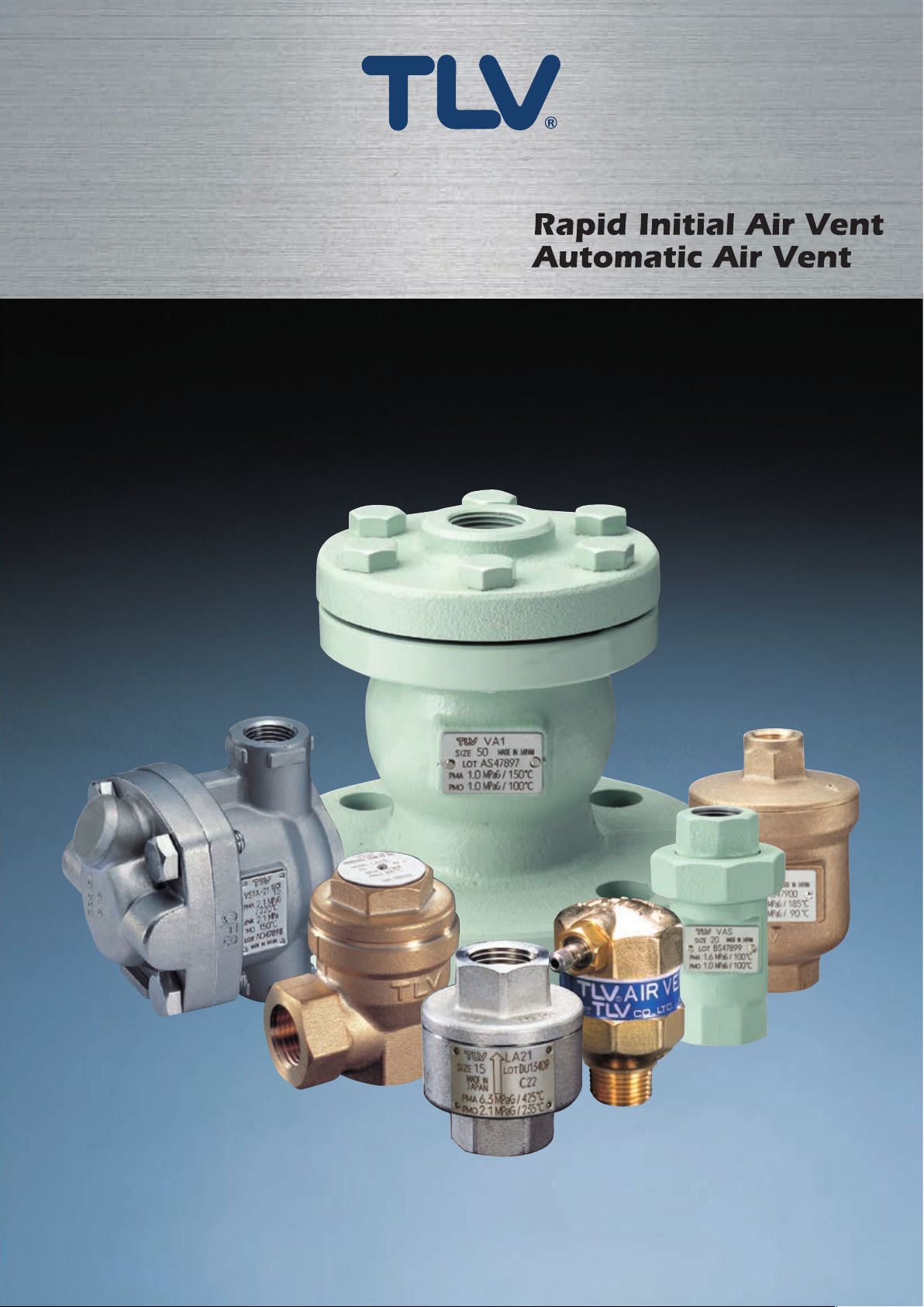
AIR VENTS
Pamphlet M3600
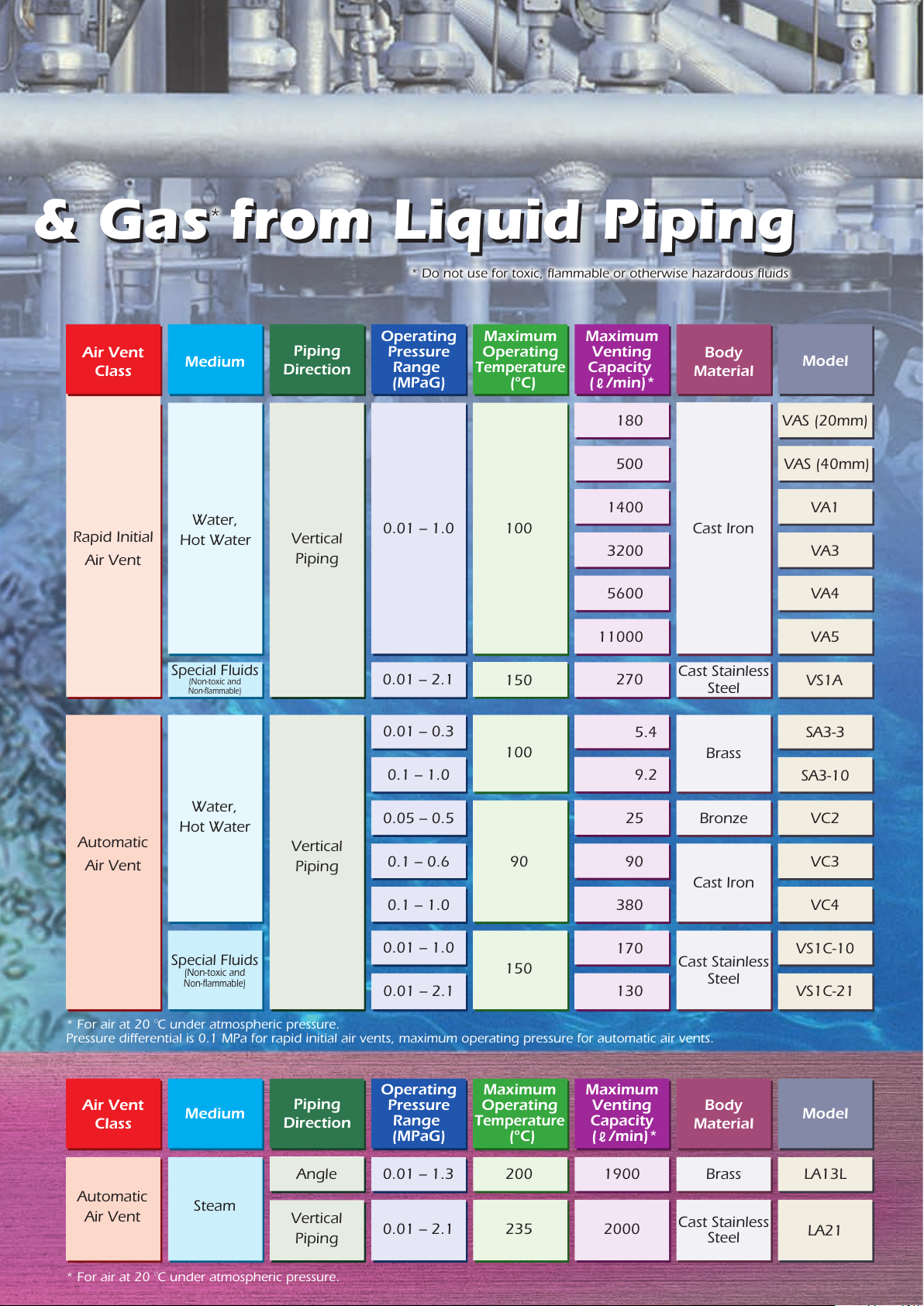
Free Float for Venting Air & Gas from Liquid Piping
Free Float for Venting Air & Gas from Liquid Piping
X-element for Venting Air & Gas from Steam Systems
X-element for Venting Air & Gas from Steam Systems
VAS VA Series VS1A
LA Series
SA3 VC Series VS1C
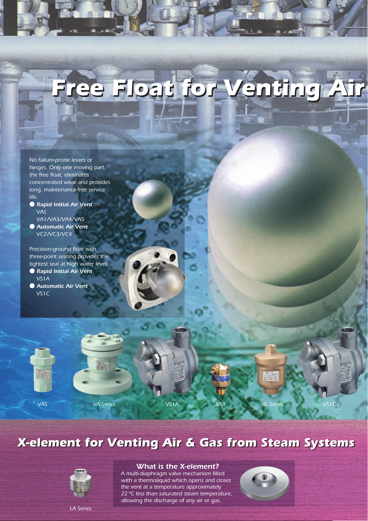
No failure-prone levers or
hinges. Only one moving part,
the free float, eliminates
concentrated wear and provides
long, maintenance-free service
life.
● Rapid Initial Air Vent
VAS
VA1/VA3/VA4/VA5
● Automatic Air Vent
VC2/VC3/VC4
Precision-ground float with
three-point seating provides the
tightest seal at high water level.
● Rapid Initial Air Vent
VS1A
● Automatic Air Vent
VS1C
What is the X-element?
A multi-diaphragm valve mechanism filled
with a thermoliquid which opens and closes
the vent at a temperature approximately
22 ºC less than saturated steam temperature,
allowing the discharge of any air or gas.
*
* Do not use for toxic, flammable or otherwise hazardous fluids
Air Vent
Class
Rapid Initial
Air Vent
Water,
Hot Water
Special Fluids
(Non-toxic and
Non-flammable)
Steam
Automatic
Air Vent
Automatic
Air Vent
* For air at 20 。C under atmospheric pressure.
Pressure differential is 0.1 MPa for rapid initial air vents, maximum operating pressure for automatic air vents.
* For air at 20 。C under atmospheric pressure.
Water,
Hot Water
Special Fluids
(Non-toxic and
Non-flammable)
Vertical
Piping
Vertical
Piping
0.01 – 2.1
0.01 – 0.3
0.1 – 1.0
VAS (20mm)
VAS (40mm)
180
500
1400
3200
5600
11000
270
5.4
9.2
25
90
380
170
130
VA1
VA3
VA4
VA5
VS1A
LA13L
SA3-3
SA3-10
VC2
VC3
VC4
VS1C-10
VS1C-21
0.05 – 0.5
0.1 – 0.6 90
0.1 – 1.0
0.01 – 1.0
0.01 – 2.1
Vertical
Piping
1900
LA21
Angle 0.01 – 1.3
0.01 – 2.1
200
235 2000
Medium
Piping
Direction
0.01 – 1.0 100
150
100
150
Operating
Pressure
Range
(MPaG)
Maximum
Operating
Temperature
(ºC)
Model
Medium
Piping
Direction
Operating
Pressure
Range
(MPaG)
Maximum
Operating
Temperature
(ºC)
Model
Brass
Cast Iron
Cast Stainless
Steel
Brass
Bronze
Cast Iron
Cast Stainless
Steel
Cast Stainless
Steel
Body
Material
Air Vent
Class
Body
Material
Maximum
Venting
Capacity
(
/min)*
Maximum
Venting
Capacity
( /min)*

TLV Air Vents
TLV Air Vents
For Liquid
For Liquid
Rapid Initial Air Vent
VAS / VA Series / VS1A
Used for venting large
amounts of initial air or gas at
system start-up. Once the
valve closes after discharging
initial air, it will not open
again, even if air accumulates
inside the product, until the
internal pressure drops to
near atmospheric pressure.
If air is expected to accumulate in the piping
during operation, use together with an
automatic air vent.
Automatic Air Vent
SA3 / VC Series / VS1C
Discharge air or gas
automatically as it enters the
vent at start-up and during
operation. Facilitates
drainage of the system by
introducing air at system
shutdown.
If a large volume of air needs to be discharged at
start-up, use together with a rapid initial air vent.
Air Vent Class Selection
System for
Air Venting
Air Vent Class Required
Rapid Initial
Air Vent
Automatic
Air Vent
Rapid Initial Air Vent
Water ● Hot Water
VAS
a
c
a
c
t
p
t
p
m
m
o
o
C
C
Features
●
Small and compact with simple construction
●
Only one moving part, the free float, eliminates
concentrate wear and provides long service life
●
Precision-ground float and valve seat rubber
contact assures seal tightness when vent is closed
●
Also functions as a vacuum breaker
Application
●
Processes requiring the rapid supply of water
●Water supply pipe, water pump, water tank, etc.
Note: Once the valve closes it will not open again, even if air accumulates.
If air is expected to accumulate, use together with an automatic air vent.
Specifications
Model
Connection
Inlet
Size (mm)
Outlet
Body Material
Maximum Operating
Pressure (MPaG) PMO
Minimum Operating
Pressure (MPaG)
Maximum Operating
Temperature (ºC) TMO
Maximum Venting
Capacity ( /min)*
PRESSURE SHELL DESIGN CONDITIONS (NOT OPERATING CONDITIONS):
Maximum Allowable Pressure (MPaG) PMA: 1.6
Maximum Allowable Temperature (˚C) TMA: 100
20
15
180
VAS
Screwed (Rc(PT))
40
25
Cast Iron (FC250)
1.0
0.01
100
500
Water pumps
Air conditioners,
solar water heating systems
Supply water pipe,
storage tank
For Steam
LA Series
Remove air or gas from steam
systems and shorten start-up
time. Facilitates drainage of the
system by introducing air at
system shutdown.
Construction
9
2
●
10
●
8
●
1
●
6
●
No. No.Part Name Part Name
1
Body
○
2
Union
○
3
Cap Nut
○
4
Valve Seat
○
5
Valve Seat Holder
○
6
Float
○
To avoid abnormal operation, accidents or serious injury, DO NOT use this product outside of the specification range.
CAUTION
7
Float Guide
○
8
Snap Ring
○
9
Union Gasket
○
10
Valve Seat Gasket
○
11
Nameplate
○
●
3
●
5
●
4
●
11
●
7
●

Special Fluids (Non-toxic, Non-flammable)
VA Series VS1A
a
p
C
a
p
a
C
a
e
e
g
g
r
r
a
a
L
L
c
c
i
i
t
t
y
y
s
s
s
S
s
e
S
e
l
l
n
n
i
i
a
a
t
t
S
S
t
t
h
h
g
g
i
i
T
T
t
t
e
e
e
e
l
l
e
a
S
e
a
l
i
S
l
n
i
n
g
g
Features
●
Simple construction and trouble free operation
●
Only one moving part, the free float, eliminates
concentrate wear and provides long service life
●
Precision-ground float and valve seat rubber
contact assures seal tightness when vent is closed
●
Also functions as a vacuum breaker
Application
●
Processes requiring the rapid supply of water
●Water supply pipe, water pump, water tank, etc.
Note: Once the valve closes it will not open again, even if air accumulates.
If air is expected to accumulate, use together with an automatic air vent.
Specifications
Model
Inlet
Connection
Outlet
Inlet
Size (mm)
Outlet
Body Material
Maximum Operating
Pressure (MPaG) PMO
Minimum Operating
Pressure (MPaG)
Maximum Operating
Temperature (ºC) TMO
Maximum Venting
Capacity ( /min)*
PRESSURE SHELL DESIGN CONDITIONS (NOT OPERATING CONDITIONS):
Maximum Allowable Pressure (MPaG) PMA: 1.0
Maximum Allowable Temperature (˚C) TMA: 150
VA1
Screwed (Rc(PT))
50
20
1 400
VA3
Flanged (ASME 150RF)
80
32
Cast Iron (FC250)
3 200
VA4
Flanged (ASME 150RF)
100
65
1.0
0.01
100
5 600
VA5
150
100
11 000
Features
●
Achieves the tightest seal with three-point seating
●
Works in liquids with low specific gravity (ρ≥ 0.8)
●
High corrosion resistance due to stainless steel
body and fluorine rubber (FPM) valve seat
●
Useable with high pressures and temperatures
●
Also functions as a vacuum breaker
Application
●
Processes requiring rapid supply of special fluids
●Supply pipe, pump, liquid storage tank, etc.
Note: Once the valve closes it will not open again, even if air accumulates.
If air is expected to accumulate, use together with an automatic air vent.
Specifications
Model
Connection
Size (mm)
Body Material
Maximum Operating
Pressure (MPaG) PMO
Minimum Operating
Pressure (MPaG)
Maximum Operating
Temperature (ºC) TMO
Maximum Venting
Capacity ( /min)*
PRESSURE SHELL DESIGN CONDITIONS (NOT OPERATING CONDITIONS):
Maximum Allowable Pressure (MPaG) PMA: 2.1
Maximum Allowable Temperature (˚C) TMA: 220
Cast Stainless Steel (CF8)
VS1A
Screwed (Rc(PT))
15, 20, 25
2.1
0.01
150
270
Construction
5
●
2
●
4
●
8
●
●
1
●
No. No.Part Name Part Name
1
Body
○
2
Cover
○
3
Float
○
4
Cover Gasket
○
5
Cover Bolt
○
6
Valve Seat
○
* For air at 20 ºC under atmospheric pressure. Discharge capacities are for a Δp of 0.1 MPa. Larger pressure differentials have greater discharge capacities. 1 MPa = 10.197 kg/cm
7
Valve Seat Holder
○
8
Set Screw
○
9
Float Guide
○
10
Snap Ring
○
11
Nameplate
○
6
●
7
●
3
●
●
9
●
Construction
1
●
12
●
11
●
10
●
8
●
3
●
No. No.Part Name Part Name
1
Body
○
2
Cover
○
3
Float
○
4
Valve Seat
○
5
Valve Seat Gasket
○
6
Cover Gasket
○
7
Cover Bolt
○
8
Nameplate
○
9
Connector
○
10
Screw
○
11
Spring Washer
○
12
Plate
○
6
●
9
●
4
●
5
●
2
●
7
●
2

For Liquid
Automatic Air Vent
Water ● Hot Water
SA3 VC Series
l
l
l
l
a
a
m
m
S
S
e
W
i
e
W
g
i
g
t
t
h
h
g
g
i
i
L
L
h
h
t
t
Features
●
Extremely compact size
●
Auxiliary valve seat enables maintenance during
operation
●
Provides a tight seal, even at extremely low
pressure (0.01 MPa for SA3 with no.3 orifice)
Application
●
Suitable for small and narrow installation spaces
●
Suitable for small air conditioning equipment
●Fan coil, radiator, etc.
Specifications
Model
Connection
Size (mm)
Body Material
Orifice Number
Maximum Operating
Pressure (MPaG) PMO
Minimum Operating
Pressure (MPaG)
Maximum Operating
Temperature (ºC) TMO
Maximum Venting
Capacity ( /min)*
PRESSURE SHELL DESIGN CONDITIONS (NOT OPERATING CONDITIONS):
Maximum Allowable Pressure (MPaG) PMA: 1.0
Maximum Allowable Temperature (˚C) TMA: 100
3
0.3
0.01
5.4
SA3
Screwed (Rc(PT))
10, 15, 20
Brass (C3771)
10
1.0
0.1
100
9.2
Features
●
Simple construction and trouble free operation
●
Only one moving part, the free float, eliminates
concentrate wear and provides long service life
●
Free float and valve seat with rubber contact
assures seal tightness when vent is closed
●
Also functions as a vacuum breaker
Application
●
General use air vent
●Water supply pipe, cooling/heating equipment,
etc.
Specifications
Model
Connection
Inlet
Size (mm)
Outlet
Body Material
Maximum Operating
Pressure (MPaG) PMO
Minimum Operating
Pressure (MPaG)
Maximum Operating
Temperature (ºC) TMO
Maximum Venting
Capacity ( /min)*
PRESSURE SHELL DESIGN CONDITIONS (NOT OPERATING CONDITIONS):
Maximum Allowable Pressure (MPaG) PMA: 0.5 (VC2), 0.6 (VC3), 1.0 (VC4)
Maximum Allowable Temperature (˚C) TMA: 185 (VC2), 220 (VC3), 150 (VC4)
VC2
15
Bronze (CAC406)
0.5
0.05
25
VC3
Screwed (Rc(PT))
10
Cast Iron (FC250)
0.6
0.1
90
90
VC4
25
1.0
0.1
380
Construction
No. Part Name
Body
1
○
Valve Seat
2
○
Base
3
○
Float
4
○
Valve Holder
5
○
Coil Spring
6
○
Siphon Rod
7
○
Body Gasket
8
○
Valve
9
○
Valve Seat Holder
10
○
O-ring
11
○
Snap Ring
12
○
Valve Seat
13
○
To avoid abnormal operation, accidents or serious injury,DO NOT use this product outside of the specification range
CAUTION
No. Part Name
Nameplate
14
○
Worm-drive Clamp
15
○
Clamp Screw
16
○
Construction
No. Part Name
1
Body
○
2
Cover
○
3
Float
○
4
Valve Seat
○
5
Cover Gasket
○
6
Nameplate
○
2
●
1
●
3
●
4
●
5
●
6
●

Special Fluids (Non-toxic, Non-flammable)
For Steam
VS1C
s
s
S
s
s
S
e
t
e
l
l
n
n
i
i
a
a
t
t
S
S
t
t
h
h
g
g
i
i
T
T
Features
●
Achieves the tightest seal with three-point seating
●
Works in liquids with low specific gravity (ρ≥0.8)
●
High corrosion resistance due to stainless steel
body and fluorine rubber (FPM) valve seat
●
Useable with high pressures and temperatures
●
Also functions as a vacuum breaker
Application
●
Suitable for facilities and piping using special fluids
●Supply pipe, pump, liquid storage tank, etc.
Specifications
Model
Connection
Size (mm)
Body Material
Orifice Number
Maximum Operating
Pressure (MPaG) PMO
Minimum Operating
Pressure (MPaG)
Maximum Operating
Temperature (ºC) TMO
Maximum Venting
Capacity ( /min)*
PRESSURE SHELL DESIGN CONDITIONS (NOT OPERATING CONDITIONS):
Maximum Allowable Pressure (MPaG) PMA: 2.1
Maximum Allowable Temperature (˚C) TMA: 220
Cast Stainless Steel (CF8)
10
1.0
170
VS1C
Screwed (Rc(PT))
15, 20, 25
0.01
150
t
e
e
e
e
l
l
a
e
l
a
i
e
S
l
n
i
S
21
2.1
130
n
g
g
LA Series
e
n
e
n
m
t
m
t
a
a
c
t
c
t
LA21
15
(CF8)
2.1
0.01
235
2 000
e
e
l
X
C
X
C
l
e
e
-
-
p
p
m
m
o
o
Features
●
Vents hot air up to just 22 ºC below saturated
steam temperature
●
Fail-open mechanism
●
High heat resistance
●
Compact with large venting capacity
Application
●
Batch processes requiring large volume air venting
●
Where hot-air locking occurs during operation
●Double-jacketed kettle, pressing machine, etc.
Specifications
Model
Connection
Size (mm)
Body Material
Maximum Operating
Pressure (MPaG) PMO
Minimum Operating
Pressure (MPaG)
Maximum Operating
Temperature (ºC) TMO
Maximum Venting
Capacity ( /min)*
PRESSURE SHELL DESIGN CONDITIONS (NOT OPERATING CONDITIONS):
Maximum Allowable Pressure (MPaG) PMA: 1.6 (LA13L), 6.3 (LA21)
Maximum Allowable Temperature (˚C) TMA: 220 (LA13L), 425 (LA21)
LA13L
Screwed (Rc(PT))
15, 20
Brass (C3771)
1.3
0.01
200
1 900
Cast Stainless Steel
Construction
1
●
12
●
11
●
10
●
8
●
3
●
No. Part Name No. Part Name
1
Body
○
2
Cover
○
3
Float
○
4
Valve Seat
○
5
Valve Seat Gasket
○
6
Cover Gasket
○
7
Cover Bolt
○
8
Nameplate
○
9
Connector
○
10
Screw
○
11
Spring Washer
○
12
Plate
○
Construction
6
●
9
●
4
●
5
●
2
●
7
●
* For air at 20 ºC under atmospheric pressure and maximum operating pressure. 1 MPa = 10.197 kg/cm
4
●
6
●
7
●
5
●
LA21 LA13L
No. Part Name No. Part Name
Body
1
○
Cover
2
○
X-element
3
○
Valve Seat
4
○
●
●
●
●
2
8
3
1
5
○
6
○
7
○
8
○
Screen
Nameplate
Snap Ring
Cover Gasket
2

Application Examples
For Liquid
For Steam
Rapid Initial Air Vent
Automatic Air Vent
VC2
SA3
LA21
VA1
Note:・Inlet piping with no horizontal portion is recommended for water/air displacement. If there is a horizontal portion, make the pipe diameter of the
horizontal portion larger than the vertical portion or make the horizontal portion as short as possible.
・Make sure the inlet piping diameter is at least as large as the product’s inlet diameter. For the inlet connection especially for products* with a nominal
diameter of 15 mm, use a pipe/fitting, etc. with an inner diameter of at least 16 mm, such as a schedule 40 pipe nipple with a nominal diameter of
15 mm. A smaller pipe may prevent water/air displacement. (*Except SA3)
Operation
For Liquid
Rapid Initial Air Vent
VA Series
Gas from inside the
piping is very
quickly pushed out
around the float
guide by liquid
pressure.
After venting, the
float rises with the
rising liquid level,
closing the valve.
Once closed, the
valve will not reopen,
even if gas enters the
vent and the water
level drops.
When the pressure
inside the piping
drops to equal to or
less than atmospheric
pressure, the float
drops, opening the
vent. Air is allowed to
enter to facilitate the
drainage of liquid
from the piping.
Automatic Air Vent
VS1C
Gas from inside
the piping is
quickly pushed
out around the
float by liquid
pressure.
For Steam
Automatic Air Vent
LA Series
Initially, the X-element
is open and gas from
inside the piping is
quickly vented,
significantly shortening
equipment start-up
time.
After venting,
the float rises
with the rising
liquid level,
closing the
valve.
When steam flows in,
the increased
temperature causes the
X-element to close
immediately. If ambient
temperature is near
steam saturation
temperature, the vent
will remain closed.
When gas flows
into the vent
body, the liquid
level decreases.
The float drops,
opening the vent
and allowing gas
discharge. When
the liquid level
rises after venting,
the float again
closes the vent.
At system
shutdown, when
the pressure
inside the piping
drops to equal to
or less than
atmospheric
pressure, air is
allowed to enter
to facilitate the
drainage of liquid
from the piping.
When the temperature
of the X-element
decreases due to
inflowing gas, the
X-element contracts
opening the vent and
allowing further gas
discharge.
881 Nagasuna, Noguchi, Kakogawa, Hyogo 675-8511, JAPAN
Tel: [81]-(0)79-427-1818 Fax: [81]-(0)79-425-1167
E-mail: tlv-japan@tlv.co.jp https://www.tlv.com
Copyright
(M)
C
TLV
Specifications subject to change without notice.
Pamphlet M3600 Rev. 10/2020
 Loading...