


A3N •AF3N
THERMODYNAMIC STEAM TRAP
INSTRUCTION MANUAL
Keep this manual in a safe place for future reference
MODEL A3N•AF3N
Copyright (C) 2018 by TLV CO., LTD. All rights reserved.
881 Nagasuna, Noguchi, Kakogawa, Hyogo 675-8511, Japan
Manufacturer
Tel: [81]-(0)79-422-1122 Fax: [81]-(0)79-422-0112
Option
BD2
( )
1. Safety Considerations
• Read this section carefully before use and be sure to follow the instructions.
• Installation, inspection, maintenance, repairs, disassembly, adjustment and valve
opening/closing should be carried out only by trained maintenance personnel.
• The precautions listed in this manual are designed to ensure safety and prevent equipment
damage and personal injury. For situations that may occur as a result of erroneous handling,
three different types of cautionary items are used to indicate the degree of urgency and the
scale of potential damage and danger: DANGER, WARNING and CAUTION.
• The three types of cautionary items above are very important for safety; be sure to observe
all of them, as they relate to installation, use, maintenance, and repair. Furthermore, TLV
accepts no responsibility for any accidents or damage occurring as a result of failure to
observe these precautions.
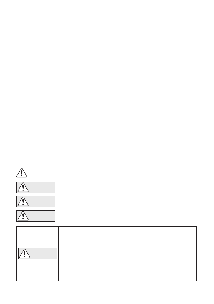
Indicates an urgent situation that poses a threat of death or serious injury.
Indicates a DANGER, WARNING or CAUTION item.
Indicates that there is a potential threat of death or serious injury.
WARNING
DANGER
CAUTION
Indicates that there is a possibility of injury, or equipment/product
damage.
CAUTION
Install properly and DO NOT use this product outside the recommended
operating pressure, temperature and other specification ranges.
Improper use may result in such hazards as damage to the product or
malfunctions, which may lead to serious accidents. Local regulations may
restrict the use of this product to below the conditions quoted.
Take measures to prevent people from coming into direct contact
with product outlets. Failure to do so may result in burns or other injury
from the discharge of fluids.
DO NOT subject this product to condensate loads that exceed its
discharge capacity. Failure to observe this precaution may lead to
condensate accumulation upstream of the trap, resulting in reduced
equipment performance or damage to the equipment.
Continued on next page
Introduction
Before beginning installation or maintenance, please read this manual to ensure correct use of the
product. Keep the manual in a safe place for future reference.
The A3N·AF3N steam trap can be used without adjustment for medium capacity applications
between 0.03 and 1.6 MPaG* (4 and 230 psig). This model is suitable for steam equipment
that discharges condensate at temperatures slightly below saturation temperature, as
well as for discharging condensate from steam mains, branch pipes, tracing, etc.
* For DIN, 13 barg
1 MPa = 10.197 kg/cm
2
, 1 bar = 0.1 MPa
For products with special specifications or with options not included in this manual, contact TLV
for instructions.
The contents of this manual are subject to change without notice.
1
CAUTION
When disassembling or removing the product, wait until the internal
pressure equals atmospheric pressure and the surface of the
product has cooled to room temperature. Disassembling or removing
the product when it is hot or under pressure may lead to discharge of
fluids, causing burns, other injuries or damage.
Be sure to use only the recommended components when repairing
the product, and NEVER attempt to modify the product in any way.
Failure to observe these precautions may result in damage to the product
or burns or other injury due to malfunction or the discharge of fluids.
Use only under conditions in which no freeze-up will occur. Freezing
may damage the product, leading to fluid discharge, which may cause
burns or other injury.
Use under conditions in which no water hammer will occur. The
impact of water hammer may damage the product, leading to fluid
discharge, which may cause burns or other injury.
2. Specifications
To avoid malfunctions, product damage, accidents or serious injury,
install properly and DO NOT use this product outside the specification
range. Local regulations may restrict the use of this product to below the
conditions quoted.
CAUTION
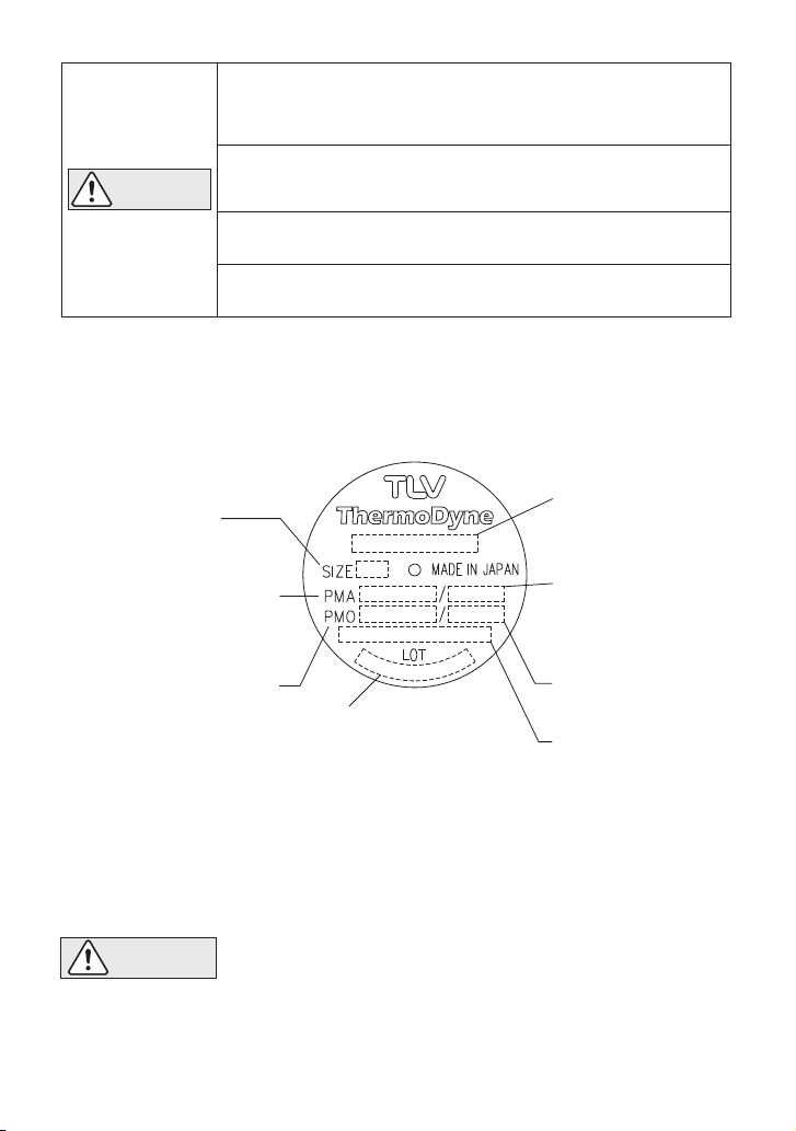
Refer to the product nameplate for detailed specifications.
* Maximum allowable pressure (PMA) and maximum allowable temperature (TMA) are
PRESSURE SHELL DESIGN CONDITIONS, NOT OPERATING CONDITIONS.
** "Valve No." is displayed for products with options. This item is omitted from the
nameplate when there are no options.
Minimum Operating Pressure: 0.03 MPaG (5 psig)
Maximum Allowable Back Pressure: 80% of inlet pressure
Maximum Allowable Pressure*
Maximum Operating Pressure
Production Lot No.
Valve No.**
Nominal Diameter
Max. Operating
Temperature TMO
Max. Allowable
Temperature* TMA
Model
2
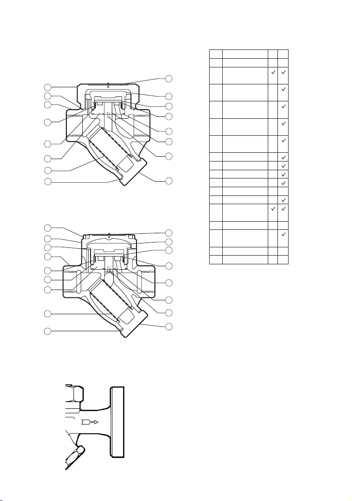
3. Configuration Aufbau Configuration
Screwed
A3N
Screwed
A3N
Flanged
AF3N
1
6
3
13
12
8
17
11
2
7
4
5
9
10
14
15
- 1″
″
/
1
2
15 - 25 mm
13
14
12
10
15
17
16
8
7
4
5
9
2
3
6
1
32 - 50 mm
- 2″
″
/
1
4
1
11
* M = Maintenance Kit; R = Repair Kit
** Integral part of Inner Cover
*** Integral part of Module Valve Seat
DescriptionNo.
1
2
3
4
5
6
7
8
9
10
11
12
13
14
15
16
17
Body
Outer Cover
Gasket
Inner Cover
Gasket**
Outer Module
Gasket***
Inner Module
Gasket***
Module Valve
Seat
Disc
Inner Cover
Air Vent Ring
Module Pin
Outer Cover
Screen
Screen Holder
Gasket
Screen Holder
Disc Holder
Ring
Cover Bolt
Nameplate
M*
-
-
-
-
-
-
-
-
-
-
-
-
-
-
-
R*
-
-
-
-
-
3

4. Exploded View
Disc
Disc Holder Ring
Nameplate
Air Vent Ring
Module Valve Seat
Module Pin
Outer Module Gasket
Inner Module Gasket
Body
Outer Cover
Cover Bolt
Inner Cover
Screen Holder
If drawings or other special documentation were supplied for the product, any
torque given there takes precedence over values shown here.
Screen Holder Gasket
Screen
Tightening Torque and Distance Across Flats
Part
N.m
220
220
80
(lbf·ft)
(160)
(160)
(59)
1
/
2
mm
(in)
13
71
(2 )
—
13
(1 )
46
(1 )
38
Outer Cover
Outer Cover Gasket
Inner Cover
Inner Cover Gasket
Screen Holder
32 - 50 mm (1 " - 2")15 - 25 mm ( " - 1")
(lbf·ft)
N.m
/
16
50
400
16
/
1
300
2
/
1
/
4
mm
—
16
75
54
〜
〜
( )
(2 )
(2 )
(37)
(290)
(220)
1 N.m 10 kg.cm
(in)
5
15
8
/
16
/
1
8
/
4

1.
Before installation, be sure to remove all protective seals.
2.
The trap can be installed either horizontally or vertically, but make sure the arrow on the trap
points in the direction of flow.
3.
Before installing the trap, blow out the inlet piping to remove all dirt and oil.
4.
Install the trap in the lowest part of the pipeline or equipment so the condensate flows naturally
into the trap by gravity. The inlet pipe should be as short and have as few bends as possible.
5.
Support the pipes properly within 800 mm (2.5 ft) on either side of the trap.
6.
Install a bypass valve to discharge condensate, and inlet and outlet valves to isolate the trap in
the event of trap failure or when performing maintenance.
7.
Install a check valve at the trap outlet whenever the condensate discharge pipe leads to a tank
or recovery line, or whenever the condensate collection pipeline is connected with more than
one trap.
8. In order to avoid excessive back pressure, make sure the discharge pipes are large enough (the
outlet back pressure should be no more than 80% of the inlet steam pressure).
9.
The use of unions is recommended to facilitate connection and disconnection of the screwed
version.
5. Proper Installation
6. Piping Arrangement
Requirement
Diameter is too small.
Diameter is too small
and inlet protrudes
into pipe.
Rust and scale flow
into the trap with the
condensate.
Condensate collects
in the pipe.
Correct
Incorrect
Install a catchpot of the
proper diameter.
Make sure the flow of
condensate is not
obstructed.
To prevent rust and scale
from flowing into the trap,
connect the inlet pipe 25 50 mm (1 - 2 in) above the
base of the T - pipe.
When installing on the blind
end, make sure nothing
obstructs the flow of
condensate.
• Installation, inspection, maintenance, repairs, disassembly, adjustment
and valve opening/closing should be carried out only by trained
maintenance personnel.
• Take measures to prevent people from coming into direct contact with
product outlets.
• Install for use under conditions in which no freeze-up will occur.
• Install for use under conditions in which no water hammer will occur.
CAUTION
Check to make sure that the pipes connected to the trap have been installed properly.
1. Is the pipe diameter suitable, and has sufficient space been secured for maintenance?
2. Has the trap been installed with the arrow on the body pointing in the direction of flow?
3. Have maintenance valves been installed at the inlet and outlet? If the outlet is subject to
back pressure, has a check valve been installed?
4. Is the inlet pipe as short as possible, with as few bends as possible, and installed so that the
condensate will flow naturally down into the trap?
5. Has the piping work been done correctly, as shown in the table below?
5

7. Operational Check
(When conducting a visual inspection, flash steam is sometimes mistaken for steam leakage. For
this reason, the use of a steam trap diagnostic instrument such as TLV TrapMan is highly
recommended.)
Operational inspections should be performed at least twice per year, or as called for by trap
operating conditions. Steam trap failure may result in temperature drop in the equipment, poor
product quality or losses due to steam leakage.
Normal:
Condensate is discharged in a short blast followed by a longer period of no
drainage. During the discharge, flash steam may be seen. A small amount of flash
steam may be visible after the discharge.
Blocked:
(Discharge
Impossible)
No condensate is discharged. The trap is quiet and makes no noise. The surface
temperature of the trap is low.
Blowing: Live steam continually flows from the outlet, and there is a continuous metallic
sound.
Steam
Leakage:
Live steam is discharged through the trap outlet together with condensate,
accompanied by a high-pitched sound.
Chattering: The trap does not close properly. Steam is discharged from the trap in short rapid
bursts.
8. Inspection and Maintenance
• Installation, inspection, maintenance, repairs, disassembly, adjustment
and valve opening/closing should be carried out only by trained
maintenance personnel.
• Before attempting to open the trap, close the inlet and outlet isolating
valves and wait until the trap has cooled completely. Failure to do so may
result in burns.
• Be sure to use the proper components and NEVER attempt to modify the
product.
CAUTION
Body, Cover
Gaskets
Screen
Disc
Disc Holder Ring
Air Vent Ring
Module Valve Seat Surface
Check inside for damage, dirt, grease, oil film, rust or scale
Check for warping or damage
Check for clogging or corrosion damage
Check for damage or wear
Check for damage or wear
Check for damage or wear
Check for damage or wear
Parts Inspection Procedure
Flash Steam
White jet
containing
water droplets
Live Steam Leakage
Clear, slightly
bluish jet
A visual inspection can be carried out to aid in determining the necessity for immediate
maintenance or repair, if the trap is open to atmosphere. If the trap does not discharge to
atmosphere, use diagnostic equipment such as TLV TrapMan or TLV Pocket TrapMan (within its
pressure and temperature measuring range).
6

Part & No.
Outer Cover 11
[15 - 25 ( - 1)]
Outer Cover 11 /
Cover Bolt 16
[32 - 50 (
1
- 2)]
Outer Cover
Gasket 2
Inner Cover 8
Inner Cover
Gasket 3
Disc 7
Disc Holder
Ring 15
Air Vent Ring 9
Module Valve
Seat 6
Outer Module
Gasket 4
Module Pin 10
Inner Module
Gasket 5
Screen Holder 14
Holder Gasket 13
Screen 12
During Disassembly During Reassembly
Disassembly / Reassembly (to reassemble, follow procedures in reverse)
Remove with a wrench Coat threads with anti-seize, tighten to
the proper torque (page 4)
Remove bolts with a socket
wrench and detach cover
Reattach cover, coat bolt threads with
anti-seize, then tighten bolts to the
proper torque (page 4)
Replace with a new gasket only if worn or
damaged
If gasket is worn or damaged, replace
inner cover
Make sure that the seat surface (the lapped
side) is facing down toward the body
Set on the air vent ring and make sure that
it does not sit on the valve seat surface
Insert into the body levelly, aligning with the
module pin
If gasket is worn or damaged, replace
module valve seat
If gasket is worn or damaged, replace
module valve seat
Coat threads with anti-seize, then tighten to
the proper torque ( page 4)
Replace with a new gasket only if worn or
damaged
Apply anti-seize to both sides and replace gasket
Reinsert with pliers
Reinsert without bending
Reinsert without bending
Remove gasket only if worn or
damaged
Remove with a socket wrench
Do not remove
Remove, being careful not to
scratch the lapped surface
Remove without bending
Remove without bending, as it
will not return to its proper shape
Remove, being careful not to
scratch the lapped surface
Remove with pliers
Do not remove
Do not remove
Remove with a socket wrench
Remove gasket and clean sealing
surfaces
Remove gasket and clean sealing surfaces
Remove without bending
Screen is clogged with rust or scale Clean
Tighten inner cover or replace
module valve seat
Replace air vent ring
Replace disc holder ring
Clean
Disc is sticking to valve seat (due to oil, etc.)
Inner cover is loose or inner cover gasket
is damaged
Air vent ring (bimetal) is broken or worn,
causing air-binding
Disc holder ring is broken or worn,
causing air-binding
Change to trap of suitable
capacity
Trap capacity is insufficient
Study inlet/outlet pressure,
including rise in outlet pipe
Differential pressure is low
Coat threads with anti-seize, then tighten
to the proper torque (page 4)
9. Troubleshooting
If the expected performance is unachievable after installation of the trap, read chapter 5 and
chapter 6 again and check the following points for appropriate corrective measures.
Problem RemedyCause
No condensate is
discharged
(blocked) or
discharge is poor
Continued on next page
/
1
4
/
1
2
/
1
2
[15 - 25 (
- 1)]
/
1
4
[32 - 50 (
1
- 2)]
Perform a bypass blowdown, or
close the trap inlet valve and
allow the trap to cool. Correct
piping if necessary.
Steam-locking has occured
7

Problem Remedy
Steam leakage or
blowing (from
module valve
seat)
Valve chattering
(leakage)
Leakage from a
location other
than module
valve seat (via
discharge, or from
body)
Cause
Back pressure exceeds allowable value Use within pressure range
Replace disc or module valve seat
Replace disc or module valve seat
Replace or close bypass valve
Use within pressure range
Tighten inner cover or replace
module valve seat
Tighten outer cover or replace
outer cover gasket
Replace trap (study trap
capacity)
Tighten screen holder or replace
screen holder gasket
Clean
Clean
Scratches on disc or module valve seat
Disc or module valve seat is worn
Bypass valve is damaged or open
Trap is being used below minimum
operating pressure
Disc is sticking to top of cover (due to
oil, etc.)
Foreign matter or oil film on disc or
module valve seat
Inner cover is loose or module gaskets
are damaged
Outer cover is loose or outer cover
gasket is damaged
Inlet and discharge channels may be
connected, due to erosion
Screen holder is loose or screen holder
gasket is damaged
NOTE: When replacing parts with new, use the parts list for reference, and replace with parts from
the Maintenance Kit or Repair Kit. Please note that replacement parts are only available as
part of a replacement parts kit.
10. Optional Blowdown Valve BD2
Coat with Anti-Seize
Screen Holder
Troubleshooting (continued)
BD2
BD2
Clean or replace screen
Replace worn parts
Replace air vent ring or disc
holder ring
Air vent ring (bimetal) or disc holder ring
is broken and obstructing valve closure
Valve closure is obstructed by scale, etc.
Disc or valve seat is worn
For BD2 (15 - 25 mm, " - 1") For BD2 and Screen Holder (32 - 50 mm, " - 2")
2
1
/
4
1
/
1
10.1 Reassembly of Blowdown Valve
The BD2 Blowdown Valve, installed in place of the screen holder, uses internal pressure to blow
out condensate/steam, dirt and scale to the atmosphere.
CAUTION
• Installation, inspection, maintenance, repairs, disassembly, adjustment
and valve opening/closing should be carried out only by trained
maintenance personnel.
• When disassembling or removing the product, wait until the internal pressure equals
atmospheric pressure and the surface of the product has cooled to room temperature.
• Do not tighten the BD2 valve or the BD2 valve seat in excess of the appropriate tightening
torque. Over-tightening may cause breakage to threaded portions, which may cause burns,
other injuries or damage.
1. Clean the trap, BD2 threads, and sealing surfaces, and apply a small amount of anti-seize.
2. 15 - 25 mm ( " - 1"): Check gasket for damage and replace if necessary.
32 - 50 mm ( " - 2"): Replace gasket.
3. Carefully place the gasket over the threaded portion, and position carefully so that it does not
become off-center.
4. Fasten to the steam trap with the proper torque.
2
1
/
4
1
/
1
8

32 - 50 mm ( " - 2")
4
1
/
1
15 - 25 mm ( " - 1")
10.2 Operation Instructions for BD2
2
1
/
8
7
/
32
21
/
32
21
/
2
1
/
1
8
1
/
2
Torque (T) and Distance Across Flats (D)
(T): 30 N
·m (22 lbf·ft)
(D): 17 mm ( ")
Inlaid
PTFE
Gasket
(T): 80 N·m (59 lbf·ft)
(D): 38 mm ( ")
(T): 30 N·m (22 lbf·ft)
(D): 17 mm ( ")
(T): 60 N
·m (43 lbf·ft)
(D): 22 mm ( ")
(T):
300 N·m (220 lbf·ft)
(D): 54 mm ( ")
1
2
1
2
3
BD2 Valve ①
Screen Holder
Gasket
Discharge Hole
Valve Stopper Pin
Screen
Screen
Valve
Stopper Pin
Discharge Hole
BD2 Valve ①
BD2 Valve
Seat ②
BD2 Gasket
Screen Holder
Gasket
BD2
Valve Seat
(Screen Holder)
②
Screen
Holder
③
①
②
③
①
②
1 N.m 10 kg.cm
〜
〜
1. With two wrenches, firmly hold the BD2 Valve Seat (Screen Holder) ② (See table above for
distance across flats) in place while slowly opening the BD2 Valve ① (17 mm, ").
Be careful to avoid contact with fluid that will be discharged through the hole in the center of
the blowdown valve as the valve opens.
2. Close the BD2 Valve ① and tighten to a torque of 30 N·m (22 lbf·ft), and confirm that there is
no leakage. If leakage continues, dirt or scale may prevent the valve from sealing. Open and
blow out again, then try to close once more.
32
21
/
Note: Do not leave the vicinity while the blowdown valve is in the open position.
CAUTION
• Always wear eye protection and heat-resistant gloves when operating the
blowdown valve. Failure to do so may result in burns or other injury.
• When operating the blowdown valve, stand to the side well clear of the
outlet to avoid contact with internal fluids that will be discharged. Operate the valve slowly and
surely, taking care to avoid the area from which internal fluids are discharged and any fluids
deflected off piping or the ground etc. Failure to do so may result in burns or other injury.
• Do not excessively loosen the BD2 valve when opening the blowdown valve. The valve stopper
pin installed to prevent the BD2 valve from being removed may break and internal pressure may
result in the BD2 valve being blown off, leading to injuries, damage and fluid discharge, causing
burns.
15 - 25 mm ( " - 1")
2
1
/
32 - 50 mm ( " - 2")
4
1
/
1
9

11. Express Limited Warranty
Subject to the limitations set forth below, TLV Corporation, a North Carolina corporation (“TLV”)
warrants that products which are sold by it or TLV International, Inc., a Japanese corporation
(“TII”), which products (the “Products”) are designed and manufactured by TLV Co., Ltd., a
Japanese corporation (“TLVJ”), conform to the specifications published by TLV for the
corresponding part numbers (the “Specifications”) and are free from defective workmanship
and materials. With regard to products or components manufactured by unrelated third parties
(the “Components”), TLV provides no warranty other than the warranty from the third party
manufacturer(s).
Duration Of Warranty
This warranty is effective for a period of the earlier of: (i) three (3) years after delivery of Products
to the first end user in the case of sealed SST-Series Products for use in steam pressure service
up to 650 psig; (ii) two (2) years after delivery of Products to the first end user in the case of
PowerTrap
®
units; or (iii) one (1) year afterdelivery of Products to the first end user in the case of
all other Products. Notwithstanding the foregoing, asserting a claim under this warranty must be
brought by the earlier of one of the foregoing periods, as applicable, or within five (5) years after
the date of delivery to the initial buyer if not sold initially to the first end user.
ANY IMPLIED WARRANTIES NOT NEGATED HEREBY WHICH MAY ARISE BY OPERATION OF
LAW, INCLUDING THE IMPLIED WARRANTIES OF MERCHANTABILITY AND FITNESS FOR A
PARTICULAR PURPOSE AND ANY EXPRESS WARRANTIES NOT NEGATED HEREBY, ARE
GIVEN SOLELY TO THE INITIAL BUYER AND ARE LIMITED IN DURATION TO ONE (1) YEAR
FROM THE DATE OF SHIPMENT BY TLV.
Exclusive Remedy
THE EXCLUSIVE REMEDY UNDER THIS WARRANTY, UNDER ANY EXPRESS WARRANTY OR
UNDER ANY IMPLIED WARRANTIES NOT NEGATED HEREBY (INCLUDING THE IMPLIED
WARRANTIES OF MERCHANTABILITY AND FITNESS FOR A PARTICULAR PURPOSE), IS
REPLACEMENT; PROVIDED: (a) THE CLAIMED DEFECT IS REPORTED TO TLV IN WRITING
WITHIN THE APPLICABLE WARRANTY PERIOD, INCLUDING A DETAILED WRITTEN
DESCRIPTION OF THE CLAIMED DEFECT AND HOW AND WHEN THE CLAIMED DEFECTIVE
PRODUCT WAS USED; AND (b) THE CLAIMED DEFECTIVE PRODUCT AND A COPY OF THE
PURCHASE INVOICE IS RETURNED TO TLV, FREIGHT AND TRANSPORTATION COSTS
PREPAID, UNDER A RETURN MATERIAL AUTHORIZATION AND TRACKING NUMBER ISSUED
BY TLV. ALL LABOR COSTS, SHIPPING COSTS, AND TRANSPORTATION COSTS
ASSOCIATED WITH THE RETURN OR REPLACEMENT OF THE CLAIMED DEFECTIVE
PRODUCT ARE SOLELY THE RESPONSIBILITY OF BUYER OR THE FIRST END USER. TLV
RESERVES THE RIGHT TO INSPECT ON THE FIRST END USER'S SITE ANY PRODUCTS
Exceptions To Warranty
This warranty does not cover defects or failures caused by:
1. improper shipping, installation, use, handling, etc., by other than TLV or service
representatives authorized by TLV; or
2. dirt, scale or rust, etc.; or
3. improper disassembly and reassembly, or inadequate inspection and maintenance by other
than TLV or service representatives authorized by TLV; or
4. disasters or forces of nature; or
5. abuse, abnormal use, accidents or any other cause beyond the control of TLV; or
6. improper storage, maintenance or repair; or
7. operation of the Products not in accordance with instructions issued with the Products or
with accepted industry practices; or
8. use for a purpose or in a manner for which the Products were not intended; or
9. use of the Products in a manner inconsistent with the Specifications; or
10. failure to follow the instructions contained in the TLV Instruction Manual for the Product.
10

CLAIMED TO BE DEFECTIVE BEFORE ISSUING A RETURN MATERIAL AUTHORIZATION.
SHOULD SUCH INSPECTION REVEAL, IN TLV’S REASONABLE DISCRETION, THAT THE
CLAIMED DEFECT IS NOT COVERED BY THIS WARRANTY, THE PARTY ASSERTING THIS
WARRANTY SHALL PAY TLV FOR THE TIME AND EXPENSES RELATED TO SUCH ON-SITE
INSPECTION.
Exclusion Of Consequential And Incidental Damages
IT IS SPECIFICALLY ACKNOWLEDGED THAT THIS WARRANTY, ANY OTHER EXPRESS
WARRANTY NOT NEGATED HEREBY, AND ANY IMPLIED WARRANTY NOT NEGATED
HEREBY, INCLUDING THE IMPLIED WARRANTIES OF MERCHANTABILITY AND FITNESS
FOR A PARTICULAR PURPOSE, DO NOT COVER, AND NEITHER TLV, TII NOR TLVJ WILL IN
ANY EVENT BE LIABLE FOR, INCIDENTAL OR CONSEQUENTIAL DAMAGES, INCLUDING,
BUT NOT LIMITED TO LOST PROFITS, THE COST OF DISASSEMBLY AND SHIPMENT OF
THE DEFECTIVE PRODUCT, INJURY TO OTHER PROPERTY, DAMAGE TO BUYER’S OR THE
FIRST END USER’S PRODUCT, DAMAGE TO BUYER’S OR THE FIRST END USER’S
PROCESSES, LOSS OF USE, OR OTHER COMMERCIAL LOSSES. WHERE, DUE TO
OPERATION OF LAW, CONSEQUENTIAL AND INCIDENTAL DAMAGES UNDER THIS
WARRANTY, UNDER ANY OTHER EXPRESS WARRANTY NOT NEGATED HEREBY OR
UNDER ANY IMPLIED WARRANTY NOT NEGATED HEREBY (INCLUDING THE IMPLIED
WARRANTIES OF MERCHANTABILITY AND FITNESS FOR A PARTICULAR PURPOSE)
CANNOT BE EXCLUDED, SUCH DAMAGES ARE EXPRESSLY LIMITED IN AMOUNT TO THE
PURCHASE PRICE OF THE DEFECTIVE PRODUCT. THIS EXCLUSION OF CONSEQUENTIAL
AND INCIDENTAL DAMAGES, AND THE PROVISION OF THIS WARRANTY LIMITING
REMEDIES HEREUNDER TO REPLACEMENT, ARE INDEPENDENT PROVISIONS, AND ANY
DETERMINATION THAT THE LIMITATION OF REMEDIES FAILS OF ITS ESSENTIAL
PURPOSE OR ANY OTHER DETERMINATION THAT EITHER OF THE ABOVE REMEDIES IS
UNENFORCEABLE, SHALL NOT BE CONSTRUED TO MAKE THE OTHER PROVISIONS
UNENFORCEABLE.
Exclusion Of Other Warranties
THIS WARRANTY IS IN LIEU OF ALL OTHER WARRANTIES, EXPRESS OR IMPLIED, AND ALL
OTHER WARRANTIES, INCLUDING BUT NOT LIMITED TO THE IMPLIED WARRANTIES OF
MERCHANTABILITY AND FITNESS FOR A PARTICULAR PURPOSE, ARE EXPRESSLY
DISCLAIMED.
Severability
Any provision of this warranty which is invalid, prohibited or unenforceable in any jurisdiction
shall, as to such jurisdiction, be ineffective to the extent of such invalidity, prohibition or
unenforceability without invalidating the remaining provisions hereof, and any such invalidity,
prohibition or unenforceability in any such jurisdiction shall not invalidate or render
unenforceable such provision in any other jurisdiction.
13901 South Lakes Drive, Charlotte, NC 28273-6790, U.S.A.
Tel: [1]-704-597-9070 Fax: [1]-704-583-1610
Printed on recycled paper.
Rev. 7/2018 (M)PAC-65325-a
 Loading...