

172-65260m-05 (S-COS/S-COSR Pressure Reducing Valve) 27 October 2008
ISO 9001/ ISO 14001
Manufacturer
Kakogawa, Japan
is approved by LRQA LTD. to ISO 9001/14001
Pressure Reducing Valve for Steam
S-COS-16 / S-COSR-16
Copyright © 2008 by TLV CO., LTD.
All rights reserved

2
Introduction ........................................................................2
Safety Considerations........................................................3
Specifications.....................................................................5
Acceptable Operating Range.............................................5
Contents
Correct Usage of S-COS / S-COSR Pressure Reducing Valve
6
Configuration......................................................................8
Installation........................................................................10
Adjustment.......................................................................13
Maintenance.....................................................................14
Disassembly.....................................................................15
Reassembly .....................................................................20
Troubleshooting ...............................................................21
Product Warranty.............................................................24
Introduction
Thank you for purchasing the S-COS/S-COSR pressure reducing valve for
steam.
This product has been thoroughly inspected before being shipped from the factory.
When the product is delivered, before doing anything else, check the specifications
and external appearance to make sure nothing is out of the ordinary. Also be sure to
read this manual carefully before use and follow the instructions to be sure of using
the product properly.
Steam-using equipment can achieve its intended efficiency only if the steam being
used is very dry. Using steam in which matter such as condensate, scale, types of
grease or air is entrained can result not only in problems with the steam-using
equipment and in lowered productivity, but can also lead to shortened service life for
and malfunction of the pressure reducing valves.
The
problems and makes possible the supply of very dry steam at a constant pressure.
Both the
conventional pressure reducing valves. They are designed for long service life, with
all major componets made of stainless steel for superior durability.
If detailed instructions for special order specifications or options not contained in this
manual are required, please contact
S-COS, with a built-in separator and steam trap, eliminates these
S-COS and S-COSR provide a more stable secondary pressure than
for full details.
This instruction manual is intended for use with the model(s) listed on the front cover.
It is needed not only for installation, but also for subsequent maintenance,
disassembly/reassembly and troubleshooting. Please keep it in a safe place for
future reference.
172-65260m-05 (S-COS/S-COSR Pressure Reducing Valve) 27 Oct 2008
3
R
Safety Considerations
• Read this section carefully before use and be sure to follow the instructions.
• Installation, inspection, maintenance, repairs, disassembly, adjustment, and valve
opening/closing should be carried out only by trained maintenance personnel.
• The precautions listed in this manual are designed to ensure safety and prevent
equipment damage and personal injury. For situations that may occur as a result
of erroneous handling, three different types of cautionary items are used to
indicate the degree of urgency and the scale of potential damage and danger:
DANGER, WARNING and CAUTION.
• The three types of cautionary items above are very important for safety: be sure to
observe all of them as they relate to installation, use, maintenance, and repair.
Furthermore, TLV accepts no responsibility for any accidents or damage occurring
as a result of failure to observe these precautions.
Symbols
Indicates a DANGER, WARNING or CAUTION item.
WARNING
DANGE
WARNING
CAUTION
Indicates an urgent situation which poses a threat of death or
serious injury
Indicates that there is a potential threat of death or serious injury
Indicates that there is a possibility of injury or equipment / product
damage
NEVER apply direct heat to the float.
The float may explode due to increased internal pressure, causing
accidents leading to serious injury or damage to property and
equipment.
CAUTION
Install properly and DO NOT use this product outside the
recommended operating pressure, temperature and other
specification ranges.
Improper use may result in such hazards as damage to the product
or malfunctions that may lead to serious accidents. Local regulations
may restrict the use of this product to below the conditions quoted.
DO NOT use the product in excess of the maximum operating
pressure differential.
Such use could make discharge through the steam trap impossible
(blocked).
Take measures to prevent people from coming into direct
contact with product outlets.
Failure to do so may result in burns or other injury from the
discharge of fluids.
When disassembling or removing the product, wait until the
internal pressure equals atmospheric pressure and the surface
of the product has cooled to room temperature.
Disassembling or removing the product when it is hot or under
pressure may lead to discharge of fluids, causing burns, other
injuries or damage.
172-65260m-05 (S-COS/S-COSR Pressure Reducing Valve) 27 Oct 2008
Safety considerations are continued on the next page.
4
CAUTION
Be sure to use only the recommended components when
repairing the product, and NEVER attempt to modify the
product in any way.
Failure to observe these precautions may result in damage to the
product and burns or other injury due to malfunction or the discharge
of fluids.
Do not use excessive force when connecting threaded pipes to
the product.
Over-tightening may cause breakage leading to fluid discharge,
which may cause burns or other injury.
Use only under conditions in which no freeze-up will occur.
Freezing may damage the product, leading to fluid discharge, which
may cause burns or other injury.
Use only under conditions in which no water hammer will
occur.
The impact of water hammer may damage the product, leading to
fluid discharge, which may cause burns or other injury.
172-65260m-05 (S-COS/S-COSR Pressure Reducing Valve) 27 Oct 2008
Specifications
CAUTION
CAUTION
Install properly and DO NOT use this product outside the recommended
operating pressure, temperature and other specification ranges.
Improper use may result in such hazards as damage to the product or
malfunctions which may lead to serious accidents. Local regulations
may restrict the use of this pr oduct to below the conditions quoted.
DO NOT use the trap in excess of the maximum operating pressure
differential; such use could make discharge imp o ssib le (block e d ).
5
CAUTION
Use only under conditions in which no freeze -up will occur. Freezing
may damage the product, leading to fluid discharge, which may cause
burns or other injury.
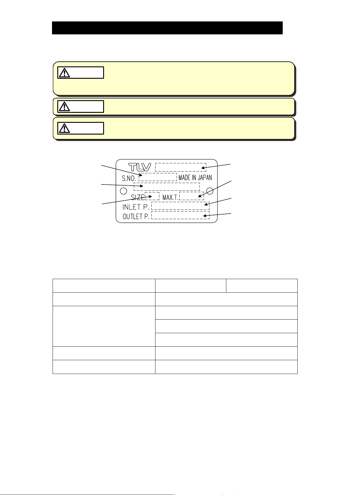
Refer to the product nameplate for detailed specifications.
Serial Number
Valve No.*
Nominal Diameter
* Valve No. is displayed for products with options. This item is omitted from the nameplate
when there are no options.
Model
Maximum Operating
Temperature
Primary Pressure Range
Secondary Pressure
Adjustable Range
Acceptable Operating Range
Model
S-COS-16 S-COSR-16
Primary Pressure Range 0.2 – 1.6 MPaG
Adjustable Secondary Pressure
Range
(all conditions must be met)
Within 10 – 84% of the primary pressure
Minimum adjustable pressure of 0.03 MPaG
Pressure differential between 0.07 – 0.80 MPa
Maximum Operating Temperature 220 °C
Minimum Adjustable Flow Rate 10% of rated flow rate
172-65260m-05 (S-COS/S-COSR Pressure Reducing Valve) 27 Oct 2008
6
Correct Usage of S-COS / S-COSR Pressure Reducing Valve
CAUTION
Install properly and DO NOT use this product outside the recommended
operating pressure, temperature and other specification ranges.
Improper use may result in such hazards as damage to the product or
malfunctions which may lead to serious accidents. Local regulations
may restrict the use of this product to below the conditions quoted.
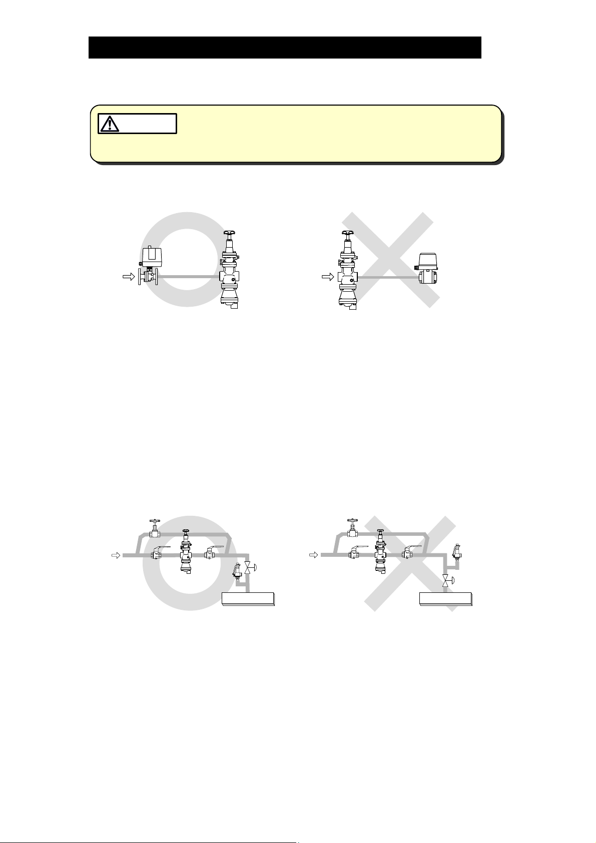
1. The pressure reducing valve should be operated only within its specifications.
2. Installing an ON / OFF Valve (Solenoid Valve or Motorized Valve)
Motorized
Valve
Inlet Side Outlet Side
PRV
PRV
Solenoid
Valve
If an on-off valve, such as a motorized valve, is required to stop supply of steam
to the steam-using equipment, install it at the inlet side of the pressure reducing
valve. If a solenoid valve is installed at the outlet of the reducing valve, its
opening and closing will cause heavy chattering and may lead to damage of the
piston and main valve. (When the on-off valve opens, the secondary pressure of
the reducing valve changes from zero to the set pressure. Passing through an
area of the reducing ratio of less than 10:1, where adjustment is impossible,
chattering occurs momentarily. To save energy, install the on-off valve as near to
the boiler as possible.
NOTE: To prevent water hammer, it is recommended that a slow-acting
motorized on-off valve be used. In particular, if a fast-acting on-off solenoid valve
is used for frequent temperature control, the potential water hammer effect can
damage the steam equipment and the pressure reducing valve.
3. Installing a Control Valve
Safety
Valve
Control
PRV
Safety
Valve
Equipment
Valve
PRV
Control
Valve
Equipment
A control valve installed between the pressure reducing valve and the steam
equipment (downstream of the reducing valve) for controling equipment
temperature may raise the pressure between the pressure reducing valve and
the control valve when the control valve is closed, depending on the spatial
relationship. A safety valve should be installed downstream of the control valve.
Note: When installing a safety valve to protect the steam equipment, be sure to
install it on the steam equipment or directly before the inlet of the steam
equipment. If the safety valve is installed on the outlet side of the pressure
reducing valve between the pressure reducing valve and a control valve, an
eventual pressure rise could activate the safety valve.
172-65260m-05 (S-COS/S-COSR Pressure Reducing Valve) 27 Oct 2008

7
4. Precautions for the Installation of Additional Fittings Before or After the Reducing
Valve
In order to ensure stable steam flow, the piping upstream and downstream of the
reducing valve must be straight runs. If a pressure reducing valve is installed
either directly before or after an elbow or control valve, unevenness in steam
flow may result in chattering and unstable pressure.
To ensure stable steam flow, it is recommended that the pressure reducing valve
be installed on straight runs of piping, as illustrated below.
① Inlet (primary side) of the pressure reducing valve NOTE: d = pipe diameter
Maintain a straight piping
run of 10 d or more
when a
manual valve, a strainer or
an elbow, etc. is installed.
(Example: if nominal size is 25
mm, have 250 mm or more)
Maintain a straight piping
run of 30 d or more
when
an automated valve (on-off
valve) is installed.
(Example: if nominal size is 25
mm, have 750 mm or more)
② Outlet (secondary side) of the pressure reducing valve
Maintain a straight piping
run of 15 d or more
when
a manual valve, a strainer
or an elbow, etc. is
installed.
(Example: if nominal size is 25
mm, have 375 mm or more)
Maintain a straight piping
run of 30 d or more
when a
safety valve is installed.
(Example: if nominal size is 25
mm, have 750 mm or more)
Maintain a straight piping
run of 30 d or more
another pressure reducing
valve is installed.
pressure reduction)
(Example: if nominal size is 25
mm, have 750 mm or more)
Maintain a straight piping
run of 30 d or more
control valve or an
automated valve (on-off
valve) is installed.
(Example: if nominal size is 25
mm, have 750 mm or more)
when
(Two-stage
when a
Valve, strainer,
elbow, etc.
PRV
Valve, strainer,
elbow, etc.
PRV
Less
Valve
than
10 d
Less than
30 d
PRV
Automatic
Valve
10 d or
more
Automatic
PRV
30 d or more
PRV PRV
15 d or more
Safety
Valve
PRV PRV
30 d or more
PRV
30 d or more
PRV PRV
172-65260m-05 (S-COS/S-COSR Pressure Reducing Valve) 27 Oct 2008
30 d or more
Second
PRV
Control or
Automated Valve
Less than
15 d
Safety
Valve
Less than
30 d
Second
PRV
PRV
Less than
30 d
Control or
Automated Valve
Less than
30 d
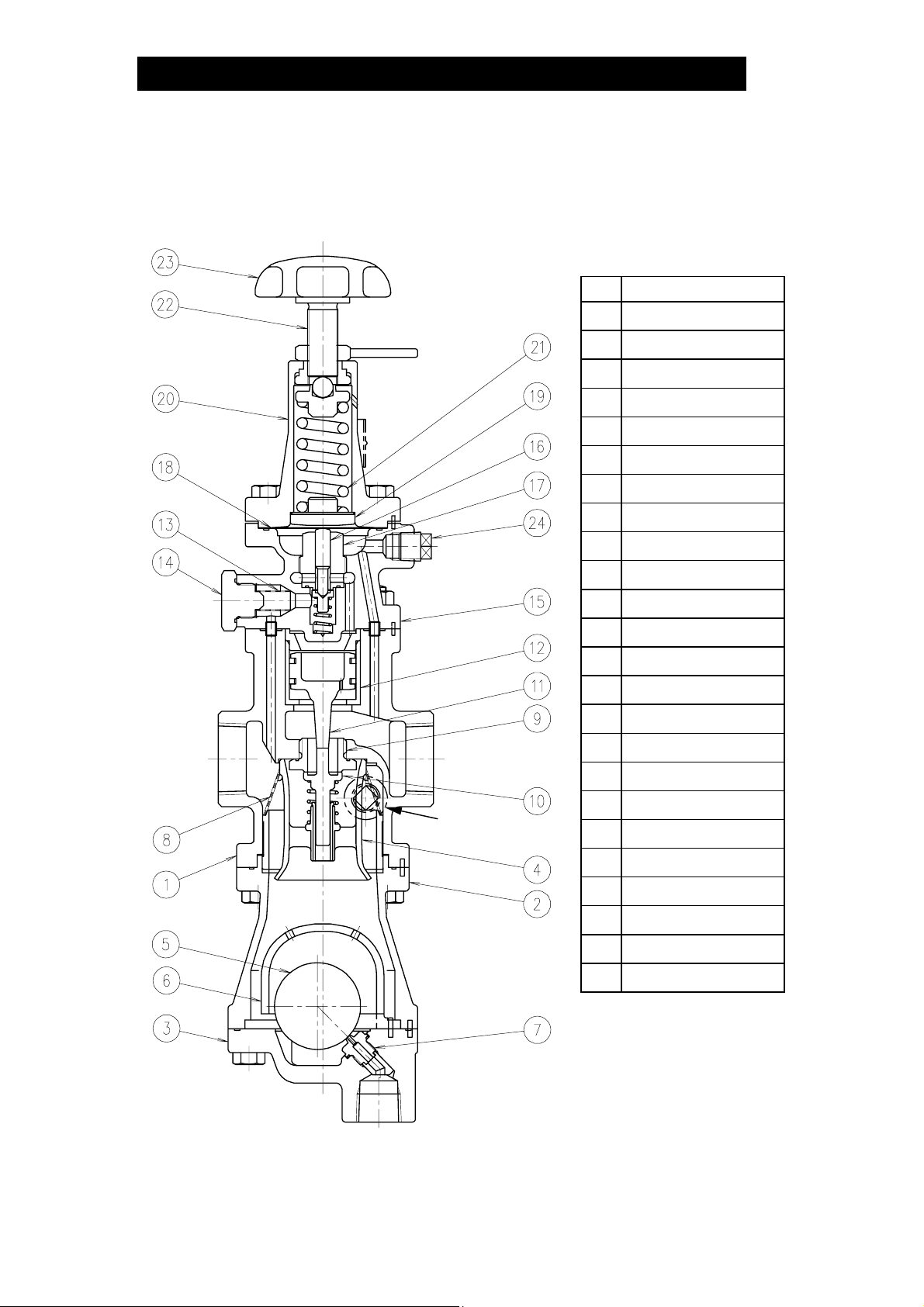
Configuration
S-COS-16
No. Name
1 Main Body
2 Trap Body
3 Trap Cover
4 Separator
5 Float
6 Float Cover
7 Trap Valve Seat
8 Separator Screen
8
Plug
(option)
9 Main Valve Seat
10 Main Valve
11 Piston
12 Cylinder
13 Pilot Screen
14 Pilot Screen Holder
15 Pilot Valve Body
16 Pilot Valve Stem
17 Pilot Valve Seat
18 Diaphragm
19 Diaphragm Support
20 Spring Housing
21 Coil Spring
22 Adjustment Screw
23 Adjustment Handle
24 Plug
172-65260m-05 (S-COS/S-COSR Pressure Reducing Valve) 27 Oct 2008
 Loading...