


TLV QuickTrap FL5, QuickTrap FL21, QuickTrap FL21-C, QuickTrap FL32-C, QuickTrap L5 Instruction Manual
...
Copyright (C) 2016 by TLV Co., Ltd. All rights reserved.
UNIVERSAL THERMOSTATIC TRAPS FL SERIES
THERMISCHE KONDENSATABLEITER FL SERIE
PURGEURS DE VAPEUR THERMOSTATIQUES GAMME FL
INSTRUCTION MANUAL
Keep this manual in a safe place for future reference
EINBAU- UND BETRIEBSANLEITUNG
Gebrauchsanleitung leicht zugänglich aufbewahren
MANUEL D UTILISATION
Conserver ce manuel dans un endroit facile d'accès
Option
BD2
( )
QuickTrap
FL5/FL21/FL32
FL5-C/FL21-C/FL32-C
Trap Unit
L5/L21/L32
L5-C/L21-C/L32-C
F46+F32
Deutsch
Français
English

Before beginning installation or maintenance, please read this manual to ensure correct use of
the product. Keep the manual in a safe place for future reference.
The FL Series steam traps (connector body unit F46 or former connector unit F32* and steam trap
units L5, L21, L32 as well as L5-C, L21-C, L32-C, with built-in check valve) can be used without
adjustment for medium capacity applications up to 0.5, 2.1, or 3.2 MPaG (75, 300, or 450 psig).
These models are suitable for steam-using equipment that discharges condensate at
temperatures slightly below saturation temperature, such as tracer lines and light process
equipment.
* Configuration of F32 differs slightly from that of F46
1 MPa = 10.197 kg/cm
2
1 bar = 0.1 MPa
For products with special specifications or with options not included in this manual, contact TLV
for instructions.
The contents of this manual are subject to change without notice.
Bitte lesen Sie die Betriebsanleitung vor Einbau und Inbetriebnahme sorgfältig durch und
bewahren Sie sie für späteren Gebrauch an einem leicht zugänglichen Ort auf, um einen
einwandfreien Betrieb des Kondensatableiters (KA) sicherzustellen.
Die thermischen Kondensatableiter der FL Serie (bestehend aus Universal-Anschlussstück F46
bzw. älterem Universalanschlussstück F32* und Kondensatableiter L5, L21, L32, sowie L5-C,
L21-C, L32-C mit Rückschlagventil) können ohne besondere Druckeinstellung für mittlere
Durchsatzleistungen bis 5, 21, 32 bar ü eingesetzt werden. Sie eignen sich besonders für
Anwendungen, bei denen Kondensat mit geringer Unterkühlung unter Sattdampftemperatur
abgeleitet werden soll, z.B. für Begleitheizungen, sowie kleinere Trocken-und Heizeinrichtungen.
* Formgebung von F32 weicht von F46 etwas ab
1 bar = 0,1 MPa
Wenden Sie sich an TLV für Sonderausführungen, die nicht in dieser Einbau-und
Betriebsanleitung enthalten sind.
Wir behalten uns vor, den Inhalt dieser Betriebsanleitung ohne Ankündigung zu ändern.
Veuillez lire attentivement ce manuel afin d’utiliser correctement le produit. Nous vous
recommandons de le garder dans un endroit sûr pour de futures consultations.
Les purgeurs de vapeur de la gamme FL (composés de l’unité de raccord F46 ou la précédente
F32* et des purgeurs L5, L21, L32 et L5-C, L21-C, L32-C avec clapet de retenue) peuvent être
utilisés sans réglage sur des applications de capacité moyenne jusqu,à 5, 21, 32 bar. Ces
modèles conviennent aux installations de chauffage évacuant le condensât à une température
légèrement inférieure à la température de saturation, telles les lignes de traçage et les petites
installations utilisant de la vapeur.
* La construction de la F32 diffère légèrement de celle de la F46
1 bar = 0,1 MPa
Pour tout produit aux spécifications particulières ou comportant des options non reprises dans ce
manuel, veuillez contacter TLV.
Einführung
Introduction
Introduction
1
English
Deutsch
Français
1. Safety Considerations
•Read this section carefully before use and be sure to follow the instructions.
•Installation, inspection, maintenance, repairs, disassembly, adjustment and valve
opening/closing should be carried out only by trained maintenance personnel.
•The precautions listed in this manual are designed to ensure safety and prevent equipment
damage and personal injury. For situations that may occur as a result of erroneous handling,
three different types of cautionary items are used to indicate the degree of urgency and the
scale of potential damage and danger: DANGER, WARNING and CAUTION.
•The three above types of cautionary items are very important for safety; be sure to observe all
of them as they relate to installation, use, maintenance, and repair. Furthermore, TLV accepts
no responsibility for any accidents or damage occurring as a result of failure to observe these
precautions.
Indicates an urgent situation that poses a threat of death or serious injury.
Indicates a DANGER, WARNING or CAUTION item.
Indicates that there is a potential threat of death or serious injury.
CAUTION
WARNING
DANGER
CAUTION
Indicates that there is a possibility of injury, or equipment/product damage.
Install properly and DO NOT use this product outside the recommended
operating pressure, temperature and other specification ranges.
Improper use may result in such hazards as damage to the product or
malfunctions, which may lead to serious accidents. Local regulations may
restrict the use of this product to below the conditions quoted.
DO NOT subject this product to condensate loads that exceed its
discharge capacity. Failure to observe this precaution may lead to
condensate accumulation upstream of the product, resulting in reduced
equipment performance or damage to the equipment.
Take measures to prevent people from coming into direct contact
with product outlets. Failure to do so may result in burns or other injury
from the discharge of fluids.
When disassembling or removing the product, wait until the internal
pressure equals atmospheric pressure and the surface of the
product has cooled to room temperature. Disassembling or removing
the product when it is hot or under pressure may lead to discharge of
fluids, causing burns, other injuries or damage.
Be sure only to use the recommended components when repairing
the product, and NEVER attempt to modify the product in any way.
Failure to observe these precautions may result in damage to the product
or burns or other injury due to malfunction or the discharge of fluids.
The pressure and temperature values displayed on the nameplate of
the connector body are the values for the connector body itself and
not for the entire trap. Improper use may result in such hazards as
damage to the product or malfunctions that may lead to serious accidents.
Use only under conditions in which no freeze-up will occur. Freezing
may damage the product, leading to fluid discharge, which may cause
burns or other injury.
Use under conditions in which no water hammer will occur. The
impact of water hammer may damage the product, leading to fluid
discharge, which may cause burns or other injury.
―2―
English
1. Sicherheitshinweise
•Bitte lesen Sie dieses Kapitel vor Beginn der Arbeiten sorgfältig durch und befolgen Sie die
Vorschriften.
•Einbau und Ausbau, Inspektion, Wartungs- und Reparaturarbeiten, Öffnen/Schließen von
Armaturen, Einstellung von Komponenten dürfen nur von geschultem Wartungspersonal
vorgenommen werden.
•Die Sicherheitshinweise in dieser Einbau- und Betriebsanleitung dienen dazu, Unfälle,
Verletzungen, Betriebsstörungen und Beschädigungen der Anlagen zu vermeiden. Für
Gefahrensituationen, die durch falsches Handeln entstehen können, werden drei verschiedene
Warnzeichen benutzt: GEFAHR; WARNUNG; VORSICHT.
•Diese drei Warnzeichen sind wichtig für Ihre Sicherheit. Sie müssen unbedingt beachtet werden,
um den sicheren Gebrauch des Produktes zu gewährleisten und Einbau, Wartung und Reparatur
ohne Unfälle oder Schäden durchführen zu können. TLV haftet nicht für Unfälle oder Schäden,
die durch Nichtbeachtung dieser Sicherheitshinweise entstehen.
bedeutet, dass eine unmittelbare Gefahr für Leib und Leben besteht.
Dieses Zeichen weist auf GEFAHR; VORSICHT; ACHTUNG hin.
bedeutet, dass die Möglichkeit der Gefahr für Leib und Leben besteht.
VORSICHT
WARNUNG
GEFAHR
VORSICHT
bedeutet dass die Möglichkeit von Verletzungen oder Schäden an
Anlagen oder Produkten besteht.
Die Einbauhinweise beachten und die spezifizierten Betriebsgrenzen
NICHT ÜBERSCHREITEN. Nichtbeachtung kann zu Betriebsstörungen
oder Unfällen führen. Lokale Vorschriften können zur Unterschreitung der
angegebenen Werte zwingen.
Das Produkt nicht bei Durchsatzmengen über der Nenndurchsatzleistung betreiben. Nichtbeachtung kann zu Kondensatrückstau
führen, wodurch die Leistung der Anlage beeinträchtigt, oder deren
Beschädigung verursacht wird.
In sicherer Entfernung von Auslassöffnungen aufhalten und andere
Personen warnen, sich fernzuhalten. Nichtbeachtung kann zu
Verletzungen durch austretende Fluide führen.
Vor Öffnen des Gehäuses und Ausbau von Teilen warten, bis der
Innendruck sich auf Atmosphärendruck gesenkt hat und das
Gehäuse auf Raumtemperatur abgekühlt ist. Nichtbeachtung kann zu
Verbrennungen oder Verletzungen durch austretende Fluide führen.
Zur Reparatur nur Original-Ersatzteile verwenden und NICHT
VERSUCHEN, das Produkt zu verändern. Nichtbeachtung kann zu
Beschädigungen führen, die Betriebsstörungen, Verbrennungen oder
Verletzungen durch austretende Fluide verursachen.
Die auf dem Typenschild des Universalanschlussstücks angezeigten
Druck- und Temperaturwerte beziehen sich nur auf das
Universalanschlusstück, nicht auf die gesamte Ableitereinheit.
Unsachgemäße Verwendung kann zu Betriebsstörungen führen, welche
Beschädigungen des Produkts oder schwere Unfälle zur Folge haben können.
Nur in frostsicherer Umgebung einsetzen. Einfrieren kann das Produkt
beschädigen, was zu Verbrennungen oder Verletzungen durch
austretende Fluide führt.
Nur an Stellen einbauen, an denen kein Wasserschlag eintreten
kann. Wasserschlag kann das Produkt beschädigen und zu
Verbrennungen oder Verletzungen durch austretende Fluide führen.
―3―
Deutsch
ATTENTION
Ne pas utiliser le purgeur à des débits de condensât supérieurs à sa
capacité. Le non-respect de cette consigne peut engendrer une
accumulation de condensât en amont du purgeur et réduire les performances
des installations, voire les endommager.
Les valeurs de pression et de température inscrites sur la plaquette apposée
sur l'unité de raccord correspondent aux caractéristiques de l'unité de
raccord elle-même et non pas à celles du purgeur. La mauvaise utilisation de
ce produit pourrait entrainer certains risques tels que des dommages au produit
lui-même ou des défaillances menant à des accidents graves.
1. Règles de sécurité
• Lire attentivement cette notice avant utilisation et suivre les instructions.
• Tout installation, inspection, entretien, réparation, démontage, réglage et
ouverture/fermeture de vanne doit être fait uniquement par une personne formée à l’entretien.
• La liste des précautions à prendre est établie afin d'assurer votre sécurité et de prévenir des
dégâts matériels et/ou des blessures sérieuses. Dans certaines situations causées par une
mauvaise manipulation, trois indicateurs sont utilisés afin d'indiquer le degré d'urgence,
l'échelle du dommage potentiel et le danger : DANGER, AVERTISSEMENT et ATTENTION.
• Ces 3 indicateurs sont importants pour votre sécurité ; observez les précautions de sécurité
énumérées dans ce manuel pour l'installation, l'utilisation, l'entretien et la réparation du produit.
TLV n'accepte aucune responsabilité en cas d'accident ou de dommage survenant à la suite
d'un non-respect de ces précautions.
Indique une situation d'urgence avec risque de mort ou de blessure grave.
Indique un DANGER, un AVERTISSEMENT ou recommande une ATTENTION.
Indique une situation pouvant entraîner la mort ou des blessures graves.
AVERTISSEMENT
DANGER
ATTENTION
Indique un risque de blessure ou de dégât matériel au produit et/ou aux
installations.
Installer le produit correctement et NE PAS l’utiliser en dehors de la
pression et de la température maximales de fonctionnement, ni en
dehors des autres plages spécifiées. Une telle utilisation peut entraîner
des dommages au produit ou des dysfonctionnements, ce qui peut
provoquer des brûlures ou autres blessures. Il se peut que des règlements
locaux limitent l'utilisation du produit en-deçà des spécifications indiquées.
Prendre les mesures appropriées afin d'éviter que des personnes
n'entrent en contact direct avec les ouvertures du produit. Le non-
respect de cette règle peut provoquer des brûlures ou autres blessures
sérieuses dues à l'écoulement des fluides.
En cas de démontage ou de manipulation du produit, attendre que
la pression interne soit égale à la pression atmosphérique et que la
surface du produit soit complètement refroidie. Le non-respect de
cette règle peut provoquer des brûlures ou autres dommages dus à
l'écoulement des fluides.
En cas de réparation, utiliser uniquement les pièces recommandées
du produit et NE JAMAIS ESSAYER de modifier le produit. Le
non-respect de cette règle peut entraîner des dommages au produit, ou
des brûlures et autres blessures sérieuses dues au dysfonctionnement
du produit ou à l'écoulement des fluides.
N'utiliser que dans des conditions où le gel ne se produit pas. Le gel
peut endommager le produit et provoquer l'écoulement des fluides, et
causer des brûlures ou autres blessures sérieuses.
Utiliser le produit dans des conditions où il n'y a aucun coup de bélier.
L'impact d'un coup de bélier peut endommager le produit et provoquer
l'écoulement des fluides, ainsi que des brûlures ou des blessures graves.
4
Français
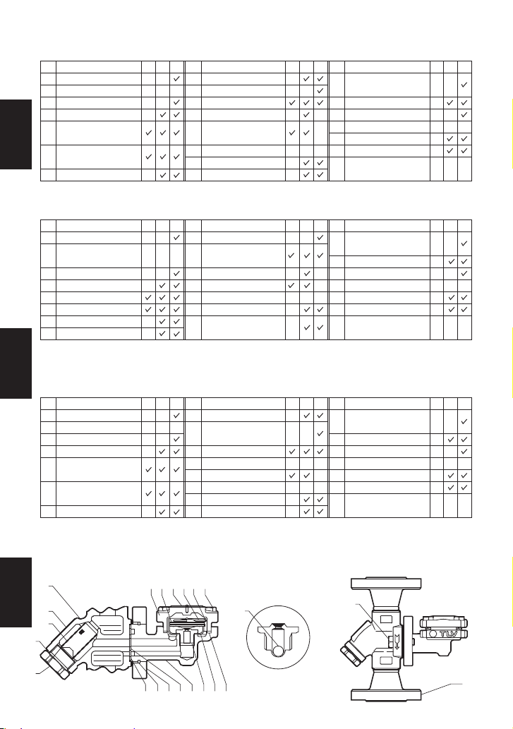
2. Configuration Aufbau Configuration
!9
No.
1
2
3
4
5
6
7
Description
Trap Body
Connector Body**
Connector Flange
Snap Ring
Outer Connector
Gasket
Inner Connector
Gasket
Valve Seat
Description
8
9
10
11
12
13
14
15
Connector Bolt
Trap Cover
Cover Gasket
Screen**
Screen Holder
Gasket**
Screen Holder**
X-element
X-element Guide
Description
16
17
18
19
20
21
22
No. No.
Nameplate
(Trap Unit)
Spring Clip
Cover Bolt
Flange
Check Valve Ball
X-element Screen
Nameplate
(Connector Unit)
M*
-
-
-
-
-
R*
-
-
-
T*
-
T*
-
M*
-
-
-
-
-
-
R*
-
-
T*
-
-
-
T*
-
-
T*
-
-
-
T*
-
-
T*
-
T*
-
-
-
T*
-
-
M*
-
-
-
-
-
-
-
R*
-
-
-
-
*
M = Maintenance Kit; R = Repair Kit; T = Trap Unit; replacement parts are available only in their respective kits.
o !4 !7!6 !5 !8
t r e y q u @1 !0
@222
@0
i
**
Replacement parts for F32 differ from those for F46. When ordering replacement parts, please
include the trap unit name, size, connection type and the connector unit name.
N°
1
2
3
4
5
6
7
Désignation
Corps du purgeur
Corps du raccord**
Bride de raccord
Anneau élastique
Joint de raccord
externe
Joint de raccord
interne
Siège de soupape
Désignation
8
9
10
11
12
13
14
15
Boulon de raccord
Couvercle du
purgeur
Joint de couvercle
Crépine**
Joint porte-crépine**
Porte-crépine**
Elément X
Guide de l’élément X
Désignation
16
17
18
19
20
21
22
N° N°
Plaquette nominative
(unité de purgeur)
Clip à ressort
Boulon de couvercle
Bride
Boule clapet de retenue
Crépine élément X
Plaquette nominative
(Unité de raccord)
E*
-
-
-
-
-
R*
-
-
-
E*
-
-
-
-
-
R*
-
-
E*
-
-
-
-
-
-
-
R*
-
-
-
-
* E = Jeu de pièces d’entretien ; R = Jeu de pièces de réparation ; T = Unité de purgeur ; les pièces
de remplacement ne sont disponibles que sous la forme de jeux de pièces
** Les pièces de rechange de l’unité de raccord F32 diffèrent de celles de la F46. Lors de la
commande de pièces de rechange, veuillez indiquer le nom du purgeur, la dimension, le
type de raccordement et le nom de l'unité de branchement.
Nr.
1
2
3
4
5
6
7
8
Bauteil
KA-Gehäuse
UniversalAnschlussstück**
Anschlussflansch
Spannring
Äußerer Dichtring
Innerer Dichtring
Ventilsitz
Halteschraube
Bauteil
9
10
11
12
13
14
15
Gehäusedeckel
KA-Gehäusedichtung
Schmutzsieb**
Stopfendichtung**
Siebhaltestopfen**
X-Element
X-ElementHalterung
Bauteil
16
17
18
19
20
21
22
Nr. Nr.
Typenschild
(KA-Einheit)
Spannbügel
Gehäuseschraube
Flansch
Rückschlagventilkugel
X-Element-Schmutzsieb
Typenschild
(Universalanschlussstück)
W*
-
-
-
-
-
-
R*
-
-
-
W*
-
-
-
-
-
R*
-
-
W*
-
-
-
-
-
-
-
R*
-
-
-
-
*
W = Wartungssatz; R = Reparatursatz; T = KA-Einheit; Ersatzteile werden nicht einzeln, sondern
als Teil dieser beiden Einheiten geliefert.
** Ersatzteile für F32 entsprechen nicht denen von F46. Bei Bestellung von Ersatzteilen
bitte unbedingt Kondensatableiter-Typ, Größe, Anschlussart und
Universalanschlussstückc-Typ angeben.
w
!1
!2
!3
English
Deutsch
Français
5
A
D
G
C
F
B
E
A
D
I
F
G
C
B
E
H
3.
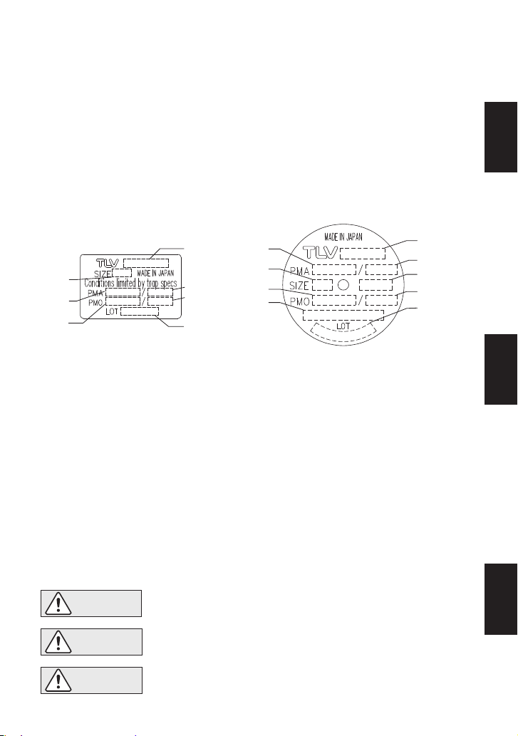
Specifications Technische Daten Données techniques
*
The nominal diameter is not printed on the trap unit nameplate when the trap unit is shipped
by itself.
** Maximum allowable pressure (PMA) and maximum allowable temperature (TMA) are
PRESSURE SHELL DESIGN CONDITIONS, NOT OPERATING CONDITIONS.
*** "Valve No." is displayed for products with options. This item is omitted from the nameplate
when there are no options.
*
Größe (DN) ist bei KA-Sätzen, die ohne Universalanschlussstück versandt werden, nicht angegeben.
** Maximal zulässiger Druck (PMA) und maximal zulässige Temperatur (TMA) sind
AUSLEGUNGSDATEN NICHT BETRIEBSDATEN.
*** Die "Valve No." wird angegeben bei Typen mit Optionen. Bei Typen ohne Optionen bleibt
diese Stelle frei.
*
Si le purgeur est livré seul, le diamètre nominal (DN) n'est pas écrit sur la plaque nominative.
** Pression maximale admissible (PMA) et Température maximale admissible (TMA) sont les
CONDITIONS DE CONCEPTION DU CORPS, PAS LES CONDITIONS DE FONCTIONNEMENT.
*** Le "Valve No." est indiqué pour des modèles avec options. Ce numéro ne figure pas sur les
modèles sans options.
Die Einbauhinweise beachten und die spezifizierten Betriebsgrenzen NICHT
ÜBERSCHREITEN. Nichtbeachtung kann zu Betriebsstörungen oder Unfällen führen.
Lokale Vorschriften können zur Unterschreitung der angegebenen Werte zwingen.
VORSICHT
Installer le produit correctement et NE PAS l’utiliser en dehors des plages
spécifiées. En cas de dépassement des limites données, des dysfonctionnements ou accidents pourraient survenir. Il se peut que des règlements
locaux limitent l'utilisation du produit en-deçà des spécifications indiquées.
ATTENTION
To avoid malfunctions, product damage, accidents or serious injury, install
properly and DO NOT use this product outside the specification range. Local
regulations may restrict the use of this product to below the conditions quoted.
CAUTION
Refer to the product nameplates on the trap unit AND on the connector body for detailed specifications. The
specifications displayed on each nameplate apply only to the unit on which it is mounted.
When the trap unit is installed on a connector unit and the PMA/TMA and/or PMO/TMO values displayed on
the two nameplates differ, the specifications for the assembled product are restricted to the lower values.
Das Universalanschlussstück sowie die KA-Einheit sind mit einem Typenschild versehen, welches die
technischen Daten der jeweiligen Einheit aufführt.
Stimmen die auf diesen beiden Typenschildern aufgeführten technischen Daten (PMA/TMA bzw. PMO/TMO)
nicht überein, so gelten für die zusammengesetzte Einheit die niedrigeren Werte.
Veuillez consulter la plaque nominative du purgeur ET celle du raccord pour les caractéristiques techniques
spécifiques de chaque pièce. Les valeurs inscrites sur une plaque nominative ne correspondent qu'aux
caractéristiques de la pièce sur laquelle la plaque est installée. Lorsqu'un purgeur et un raccord sont joints
et qu'une caractéristique technique telle que la PMO, la TMO, la PMA ou la TMA d'une pièce est inférieure à
l'autre, c'est la plus petite valeur qui correspond à la caractéristique technique de l'ensemble.
Trap Unit
KA - Einheit
Unité de purgeur
A: Model / Typ / Modèle
B: Nominal Diameter* / Größe (DN)* / Dimension (DN)*
C: Max. Allowable Press.** / Max. zulässiger Druck** / Press. max. admissible**
D: Max. Allowable Temp.** / Max. zulässige Temp.** / Temp. max. admissible** (TMA)
E: Max. Operating Press. / Max. Betriebsdruck / Press. max. de fonctionnement
F: Max. Operating Temp. / Max. Betriebstemp. / Temp. max. de fonctionnement (TMO)
G: Production Lot No. / Fertigungslos-Nr. / Lot de production n°
H: Valve No.***
I : Type of X-Element / X-Element-Typ / Type d'élément X
Connector Unit (mounted only on F46)
Universalanschlussstück (nur auf F46 montiert)
Unité de raccord (apposé sur F46 uniquement)
6
Deutsch
Français
English
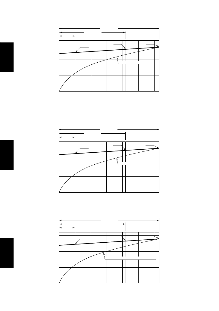
3.1 Maximum Operating Temperature
3.1 Maximale Betriebstemperatur
100
150
200
220
250
05 21 3210 15 20 25 30
Betriebsdruck (bar ü)
235˚C 240˚C
225˚C
Sattdampfkurve
Temperatur ˚C
FL5S(-C)
FL21S(-C)
FL32S(-C)
3.1 Température de fonctionnement maximale
100
150
200
220
250
05 21 3210 15 20 25 30
Pression (bar)
235˚C 240˚C
225˚C
Courbe de saturation de la vapeur
Température ˚C
FL5S(-C)
FL21S(-C)
FL32S(-C)
100
150
200
(428˚F)
220
250
212
302
392
482
0 0.5
(75)
2.1
(300)
3.2
(450)
1.0
(150)
1.5
(215)
2.0 2.5
(350)
3.0
Pressure MPaG (psig)
235˚C
455˚F
240˚C
464˚F
225˚C
437˚F
Saturated Steam Curve
Temperature ˚F
Temperature ˚C
FL5S(-C)
FL21S(-C)
FL32S(-C)
1 MPa = 10.197 kg/cm
2
1 bar = 0,1 MPa
1 bar = 0,1 MPa
―7―
English
Deutsch
Français
Part & Number
Tightening Torque and Distance Across Flats
Cover Bolt 18
Valve Seat 7
Connector Bolt 8
Screen Holder (F46) 13
Screen Holder (F32) 13
F: 15, 20, 25mm ( , ", 1")***
S&W: 15, 20mm ( " ")***
S&W: 25mm (1")***
N·m (lbf·ft)
35
35
39
100
60
150
(26)
(26)
(28)
(73)
(44)
(110)
(in) mm
13
19
14
30
22
38
( )
( )
( )
( )
( )
( )
Bauteil & Nummer
Anzugsmoment und Schlüsselweite
Gehäuseschraube 18
Ventilsitz 7
Halteschraube 8
Siebhaltestopfen (F46) 13
Siebhaltestopfen (F32) 13
F: DN 15, 20, 25***
S&W: DN 15, 20 ( " )***
S&W: DN 25 (1")***
mm
13
19
14
30
22
38
N·m
35
35
39
100
60
150
Couples de serrage et ouvertures de clé
* Trap unit L5, L21, L32 / L5-C, L21-C, L32-C
** Connector body unit F46 or F32
*** F = Flanged, S = Screwed, W = Socket welded
*
Kondensatableiter L5, L21, L32 / L5-C, L21-C, L32-C
** Universal-Anschlussstück F46 oder F32
*** F = Flansch, S = Muffe, W = Schweißmuffe
*
Unité du purgeur L5, L21, L32 / L5-C, L21-C, L32-C
** Corps du raccord F46 ou F32
*** F = À brides, S = Taraudé, W = Douille à souder
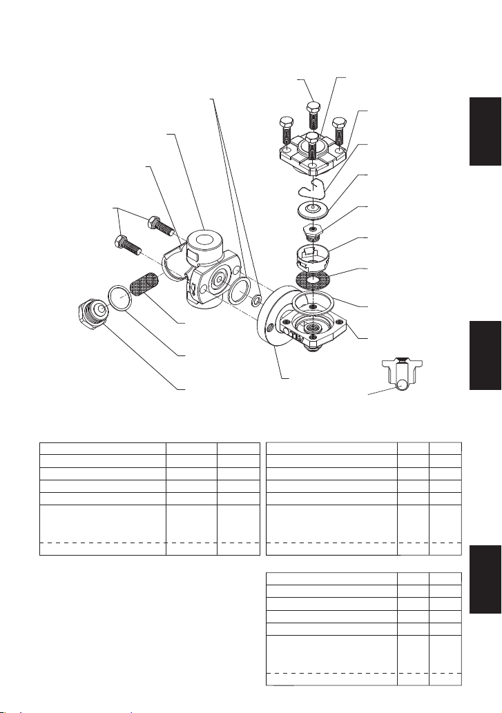
4. Exploded View Einzelteile Pièces détachées
Cover Bolt*
Gehäuseschraube*
Boulon de couvercle*
Connector Bolt*
Halteschraube*
Boulon de raccord*
Connector Nameplate**
Typenschild Anschlussstück**
Plaquette nominative de
l'unité de raccord**
Connector Body**
Universal-Anschlussstück**
Unité de raccord**
Screen**
Schmutzsieb**
Crépine**
Screen Holder Gasket**
Siebstopfendichtung**
Joint du porte-crépine**
Screen Holder**
Siebhaltestopfen**
Bouchon porte-crépine**
Check Valve Ball*
Rückschlagventilkugel*
Boule clapet de retenue*
Connector Gasket*
Dichtring*
Joint de raccord*
Trap Cover*
Gehäusedeckel*
Couvercle du purgeur*
Nameplate*
Typenschild*
Plaquette nominative*
Spring Clip*
Spannbügel*
Clip à ressort*
X-element*
X-Element*
Élément X*
Valve Seat*
Ventilsitz*
Siège de soupape*
Trap Body*
KA-Gehäuse*
Corps du purgeur*
Cover Gasket*
Gehäusedichtung*
Joint de couvercle*
Connector Flange*
Anschlussflansch*
Bride de raccord*
X-element Guide*
X-Element Halterung*
Guide élément X*
X-element Screen*
X-Element-Schmutzsieb*
Crépine élément X*
Pièce et Numéro
Boulon de couvercle 18
Siège de soupape 7
Boulon de raccord 8
Porte-crépine (F46) 13
Porte-crépine (F32) 13
F : DN 15, 20, 25***
S&W :
DN 15, 20 ( " ")***
S&W : DN 25 (1")***
mm
13
19
14
30
22
38
N·m
35
35
39
100
60
150
1 N•m 10 kg•cm
1
1
2
1
/
4
3
/
2
1
/
4
3
/
2
1
/
4
3
/
4
3
/
2
1
/
2
1
/
2
1
/
4
3
/
8
7
/
16
9
/
16
3
/
〜
〜
Do not remove snap ring used to
fix the connector flange.
Den Spannring, welcher den Anschlussflansch hält, nicht entfernen.
Ne retirez pas l'anneau élastique qui
retient la bride de raccord en place.
8
Deutsch
Français
English
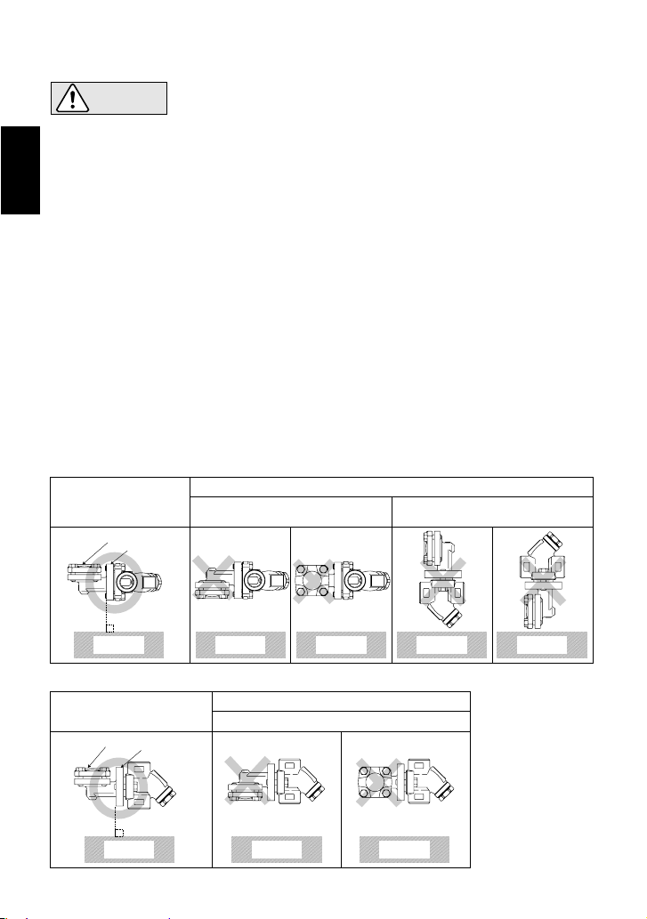
Nameplate
Connector
Flange
Installation Examples: Horizontal Piping
Installation Examples: Vertical Piping
Correct
Correct
Nameplate is not facing upwards.
Universal Connector Flange is not
in the vertical plane.
Incorrect
Incorrect
Nameplate is not facing upwards.
Ground GroundGround
Ground Ground Ground
Ground Ground
Nameplate
Connector
Flange
1. In some instances, the trap unit and the connector body are sent as separate units. When
attaching them together, make sure the connector gaskets are still in place after having
removed their protective seal (See page 12 for details).
2. There are no restrictions on the installation direction beyond the following conditions:
a) The arrow on the connector body must point in the direction of condensate flow.
b) The connector body must be adjusted so that the connector flange face (for connecting to
the trap unit) is in the vertical plane.
c) The nameplate on the trap unit must face upward.
3.
Before installation, be sure to remove all protective seals.
4.
Before installing the trap, blow out the inlet piping to remove all dirt and oil.
5.
Install the trap in the lowest part of the pipeline or equipment so the condensate flows naturally
into the trap by gravity. The inlet pipe should be as short and have as few bends as possible.
6.
Support the pipes properly within 800 mm (2.5 ft) on either side of the trap.
7.
Install a bypass valve to discharge condensate, and inlet and outlet valves to isolate the trap in
the event of trap failure or maintenance.
8.
Install a check valve at the trap outlet whenever more than one trap is connected to the
condensate collection pipeline.
9. In order to avoid excessive back pressure, make sure the discharge pipes are large enough;
(the outlet back pressure allowance should be no more than 90% of the inlet steam pressure).
10.
We recommend unions to facilitate connection and disconnection of screwed version.
5. Proper Installation
• Installation, inspection, maintenance, repairs, disassembly, adjustment
and valve opening/closing should be carried out only by trained
maintenance personnel.
• Take measures to prevent people from coming into direct contact with product outlets.
• Install for use under conditions in which no freeze-up will occur.
• Install for use under conditions in which no water hammer will occur.
CAUTION
―9―
English