

TLV P Series, PowerDyne P46SRM, PowerDyne P46SRN, PowerDyne P65SRN, PowerDyne P46SRW Instruction Manual
...
Copyright (C) 2018 by TLV CO., LTD. All rights reserved.
THERMODYNAMIC STEAM TRAPS
P SERIES
THERMODYNAMISCHE KONDENSATABLEITER
P SERIE
PURGEURS DE VAPEUR THERMODYNAMIQUES
GAMME P
热动力式蒸汽疏水阀
P
系列
INSTRUCTION MANUAL
Keep this manual in a safe place for future reference
EINBAU- UND BETRIEBSANLEITUNG
Gebrauchsanleitung leicht zugänglich aufbewahren
MANUEL D UTILISATION
Conserver ce manuel dans un endroit facile d'accès
操作说明书
请务必妥善保管此说明书,以备日后使用。
Option
BD2
( )
P46SRN / P46SRM
P65SRN
P46SRW
Deutsch
中 文
Français
English

Introduction
Before beginning installation or maintenance, please read this manual to ensure correct use of
the product. Keep the manual in a safe place for future reference.
The inline repairable P Series steam traps with thermostatic air vent, P46SRN, P46SRM,
P46SRW, P65SRN can be used without adjustment for medium capacity applications between
0.03 and 4.6 or 6.5 MPaG (5 and 650 or 925 psig), such as steam mains, tracers and coils. The
traps discharge condensate at a temperature slightly lower than saturation temperature.
1 MPa = 10.197 kg/cm
2
, 1 bar = 0.1 MPa
For products with special specifications or with options not included in this manual, contact TLV
for instructions.
The contents of this manual are subject to change without notice.
Einführung
Bitte lesen Sie die Betriebsanleitung vor Einbau und Inbetriebnahme sorgfältig durch und
bewahren Sie sie für späteren Gebrauch an einem leicht zugänglichen Ort auf.
Die in der Leitung wartbaren thermodynamischen Kondensatableiter der P Serie mit thermischem
Entlüfter, P46SRN, P46SRM, P46SRW, P65SRN, können ohne besondere Druckeinstellung für
mittlere Anlagengrößen zwischen 0,3 und 46 oder 65 bar ü eingesetzt werden. Sie eignen sich
besonders für Anwendungen, bei denen Kondensat mit geringer Unterkühlung unter
Sattdampftemperatur abgeleitet werden soll, insbesondere für Leitungsentwässerung und
Begleitheizung.
1 bar = 0,1 MPa
Wenden Sie sich an TLV für Sonderausführungen, die nicht in dieser Einbau- und Betriebsanleitung enthalten sind.
Wir behalten uns vor, den Inhalt dieser Betriebsanleitung ohne Ankündigung zu ändern.
Introduction
Veuillez lire attentivement ce manuel afin d'utiliser correctement le produit. Nous vous
recommandons de le garder dans un endroit sûr pour de futures consultations.
Les purgeurs de vapeur de la gamme P avec purgeur d'air thermostatique, c'est à dire les
modèles P46SRN, P46SRM, P46SRW et P65SRN, peuvent être utilisés sans réglage sur des
applications de capacité moyenne entre 0,3 et 46 ou 65 bar. Ces modèles conviennent aux
installations évacuant le condensât à une température légèrement inférieure à la température de
saturation, telles les conduites de vapeur, lignes de traçage, et serpentins.
1 bar = 0,1 MPa
Pour tout produit aux spécifications particulières ou comportant des options non reprises dans ce
manuel, veuillez contacter TLV.
Le contenu de ce manuel est sujet à modifications sans préavis.
1
Deutsch
Français
English

1. Safety Considerations
• Read this section carefully before use and be sure to follow the instructions.
• Installation, inspection, maintenance, repairs, disassembly, adjustment and valve
opening/closing should be carried out only by trained maintenance personnel.
• The precautions listed in this manual are designed to ensure safety and prevent equipment
damage and personal injury. For situations that may occur as a result of erroneous handling,
three different types of cautionary items are used to indicate the degree of urgency and the
scale of potential damage and danger: DANGER, WARNING and CAUTION.
• The three types of cautionary items above are very important for safety; be sure to observe
all of them, as they relate to installation, use, maintenance, and repair. Furthermore, TLV
accepts no responsibility for any accidents or damage occurring as a result of failure to
observe these precautions.
Indicates an urgent situation that poses a threat of death or serious injury.
Indicates a DANGER, WARNING or CAUTION item.
Indicates that there is a potential threat of death or serious injury.
CAUTION
WARNING
DANGER
CAUTION
Indicates that there is a possibility of injury, or equipment/product
damage.
Install properly and DO NOT use this product outside the recommended
operating pressure, temperature and other specification ranges.
Improper use may result in such hazards as damage to the product or
malfunctions, which may lead to serious accidents. Local regulations may
restrict the use of this product to below the conditions quoted.
Take measures to prevent people from coming into direct contact
with product outlets. Failure to do so may result in burns or other injury
from the discharge of fluids.
When disassembling or removing the product, wait until the internal
pressure equals atmospheric pressure and the surface of the
product has cooled to room temperature. Disassembling or removing
the product when it is hot or under pressure may lead to discharge of
fluids, causing burns, other injuries or damage.
Be sure to use only the recommended components when repairing
the product, and NEVER attempt to modify the product in any way.
Failure to observe these precautions may result in damage to the product
or burns or other injury due to malfunction or the discharge of fluids.
Use only under conditions in which no freeze-up will occur. Freezing
may damage the product, leading to fluid discharge, which may cause
burns or other injury.
Use under conditions in which no water hammer will occur. The
impact of water hammer may damage the product, leading to fluid
discharge, which may cause burns or other injury.
DO NOT subject the trap to condensate loads that exceed its
discharge capacity. Failure to observe this precaution may lead to
condensate accumulation upstream of the trap, resulting in reduced
equipment performance or damage to the equipment.
2
English
3
1. Sicherheitshinweise
• Bitte lesen Sie dieses Kapitel vor Beginn der Arbeiten sorgfältig durch und befolgen Sie die
Vorschriften.
• Einbau und Ausbau, Inspektion, Wartungs- und Reparaturarbeiten, Öffnen/Schließen von
Armaturen, Einstellung von Komponenten, dürfen nur von geschultem Wartungspersonal
vorgenommen werden.
• Die Sicherheitshinweise in dieser Einbau- und Betriebsanleitung dienen dazu, Unfälle,
Verletzungen, Betriebsstörungen und Beschädigungen der Anlagen zu vermeiden. Für
Gefahrensituationen, die durch falsches Handeln entstehen können, werden drei verschiedene
Warnzeichen benutzt: GEFAHR; WARNUNG; VORSICHT.
• Diese drei Warnzeichen sind wichtig für Ihre Sicherheit. Sie müssen unbedingt beachtet werden,
um den sicheren Gebrauch des Produktes zu gewährleisten und Einbau, Wartung und
Reparatur ohne Unfälle oder Schäden durchführen zu können. TLV haftet nicht für Unfälle oder
Schäden, die durch Nichtbeachtung dieser Sicherheitshinweise entstehen.
bedeutet, dass eine unmittelbare Gefahr für Leib und Leben besteht.
Dieses Zeichen weist auf GEFAHR; WARNUNG; VORSICHT hin.
bedeutet, dass die Möglichkeit der Gefahr für Leib und Leben besteht.
VORSICHT
WARNUNG
GEFAHR
VORSICHT
bedeutet dass die Möglichkeit von Verletzungen oder Schäden an
Anlagen oder Produkten besteht.
Die Einbauhinweise beachten und die spezifizierten Betriebsgrenzen
NICHT ÜBERSCHREITEN. Nichtbeachtung kann zu Betriebsstörungen
oder Unfällen führen. Lokale Vorschriften können zur Unterschreitung der
angegebenen Werte zwingen.
In sicherer Entfernung von Auslassöffnungen aufhalten und andere
Personen warnen, sich fernzuhalten. Nichtbeachtung kann zu
Verletzungen durch austretende Fluide führen.
Vor Öffnen des Gehäuses und Ausbau von Teilen warten, bis der
Innendruck sich auf Atmosphärendruck gesenkt hat und das
Gehäuse auf Raumtemperatur abgekühlt ist. Nichtbeachtung kann zu
Verbrennungen oder Verletzungen durch austretende Fluide führen.
Zur Reparatur nur Original-Ersatzteile verwenden und NICHT
VERSUCHEN, das Produkt zu verändern. Nichtbeachtung kann zu
Beschädigungen führen, die Betriebsstörungen, Verbrennungen oder
andere Verletzungen durch austretende Fluide verursachen.
Nur in frostsicherer Umgebung einsetzen. Einfrieren kann das Produkt
beschädigen, was zu Verbrennungen oder Verletzungen durch
austretende Fluide führt.
Nur an Stellen einbauen, an denen kein Wasserschlag eintreten
kann. Wasserschlag kann das Produkt beschädigen und zu
Verbrennungen oder Verletzungen durch austretende Fluide führen.
Das Produkt nicht bei Durchsatzmengen über der Nenndurchsatzleistung betreiben. Nichtbeachtung kann zu Kondensatrückstau führen
wodurch die Leistung der Anlage beeinträchtigt, oder deren Beschädigung verursacht wird.
Deutsch
1. Règles de sécurité
• Lire attentivement cette notice avant utilisation et suivre les instructions.
• Tout installation, inspection, entretien, réparation, démontage, ajustement et
ouverture/fermeture de vanne doit être fait uniquement par une personne formée à l’entretien.
• La liste des précautions à prendre est établie afin d'assurer votre sécurité et de prévenir des
dégâts matériels et/ou des blessures sérieuses. Dans certaines situations causées par une
mauvaise manipulation, trois indicateurs sont utilisés afin d'indiquer le degré d'urgence,
l'échelle du dommage potentiel et le danger : DANGER, AVERTISSEMENT et ATTENTION.
• Ces 3 indicateurs sont importants pour votre sécurité ; observez les précautions de sécurité
énumérées dans ce manuel pour l'installation, l'utilisation, l'entretien et la réparation du produit.
TLV n'accepte aucune responsabilité en cas d'accident ou de dommage survenant à la suite
d'un non-respect de ces précautions.
Indique une situation d'urgence avec risque de mort ou de blessure grave.
Indique un DANGER, un AVERTISSEMENT ou recommande une ATTENTION.
Indique une situation pouvant entraîner la mort ou des blessures graves.
ATTENTION
AVERTISSEMENT
DANGER
ATTENTION
Indique un risque de blessure ou de dégât matériel au produit et/ou aux
installations.
Installer le produit correctement et NE PAS l’utiliser en dehors de la
pression et de la température maximales de fonctionnement, ni en
dehors des autres plages spécifiées. Une telle utilisation peut entraîner
des dommages au produit ou des dysfonctionnements, ce qui peut
provoquer des brûlures ou autres blessures. Il se peut que des règlements
locaux limitent l'utilisation du produit en-deçà des spécifications indiquées.
Prendre les mesures appropriées afin d'éviter que des personnes
n'entrent en contact direct avec les ouvertures du produit. Le non-
respect de cette règle peut provoquer des brûlures ou autres blessures
sérieuses dues à l'écoulement des fluides.
En cas de démontage ou de manipulation du produit, attendre que
la pression interne soit égale à la pression atmosphérique et que la
surface du produit soit complètement refroidie. Le non-respect de
cette règle peut provoquer des brûlures ou autres dommages dus à
l'écoulement des fluides.
En cas de réparation, utiliser uniquement les pièces recommandées
du produit et NE JAMAIS ESSAYER de modifier le produit. Le
non-respect de cette règle peut entraîner des dommages au produit, ou
des brûlures et autres blessures sérieuses dues au dysfonctionnement
du produit ou à l'écoulement des fluides.
N'utiliser que dans des conditions où le gel ne se produit pas. Le gel
peut endommager le produit et provoquer l'écoulement des fluides, et
causer des brûlures ou autres blessures sérieuses.
Utiliser le produit dans des conditions où il n'y a aucun coup de
bélier. L'impact d'un coup de bélier peut endommager le produit et
provoquer l'écoulement des fluides, ainsi que des brûlures ou des
blessures graves.
Ne pas utiliser le purgeur à des débits de condensât supérieurs à sa
capacité. Le non-respect de cette consigne peut engendrer une
accumulation de condensât en amont du purgeur et réduire les
performances des installations, voire les endommager.
4
Français
2. Configuration Aufbau Configuration
Description
Description
M* R*M*
R*
No.
1
2
3
4
5
6
7
Body
Module Valve Seat
Cover
Disc
Disc Holder Ring
Air Vent Ring (Bimetal)
Outer Module Gasket
No.
8
9
10
11
12
13
14
Nameplate
Inner Module Gasket
Screen
Screen Holder Gasket
Screen Holder
Cap
Flange (Not shown)
* M = Maintenance Kit; R = Repair Kit; replacement parts are available only in their respective kits
W* R*W* R*
Bauteil
Bauteil
Nr.
1
2
3
4
5
6
7
Gehäuse
Ventilsitzgarnitur
Verschlusskappe
Ventilteller
Ventilteller-Haltering
Entlüftungsring (Bimetall)
Äußere Ventilsitzdichtung
Nr.
8
9
10
11
12
13
14
Typenschild
Innere Ventilsitzdichtung
Schmutzsieb
Dichtung Siebhaltestopfen
Siebhaltestopfen
Isolierkappe
Flansch (nicht gezeigt)
* W = Wartungssatz; R = Reparatursatz; Ersatzteile werden nicht einzeln, sondern als Teil dieser beiden
Einheiten geliefert.
E* R*E* R*
Désignation
Désignation
N°
1
2
3
4
5
6
7
Corps
Module siège de soupape
Couvercle
Disque
Anneau support disque
Anneau purge d'air (bimétal)
Joint module externe
N°
8
9
10
11
12
13
14
Plaquette nominative
Joint module interne
Crépine
Joint porte-crépine
Porte-crépine
Chemise isolante
Bride (non illustrée)
*E = Jeu de pièces d'entretien ; R = Jeu de pièces de réparation : Les pièces de remplacement ne sont
disponibles que sous la forme de jeux de pièces.
Deutsch
Français
English
5

3.
Exploded View Einzelteile Pièces détachées
Nameplate
Typenschild
Plaquette nominative
Cap
Isolierkappe
Chemise isolante
Cover
Verschlusskappe
Couvercle
Disc Holder Ring
Ventilteller-Haltering
Anneau support disque
Disc
Ventilteller
Disque
Air Vent Ring
Entlüftungsring
Anneau purge d'air
Module Valve Seat
Ventilsitzgarnitur
Module siège de soupape
Inner Module Gasket
Innere Ventilsitzdichtung
Joint module interne
Body
Gehäuse
Corps
Screen
Schmutzsieb
Crépine
Screen Holder Gasket
Dichtung Siebhaltestopfen
Joint porte-crépine
Screen Holder
Siebhaltestopfen
Porte-crépine
Outer Module Gasket
Äußere Ventilsitzdichtung
Joint module externe
6
Deutsch
Français
English

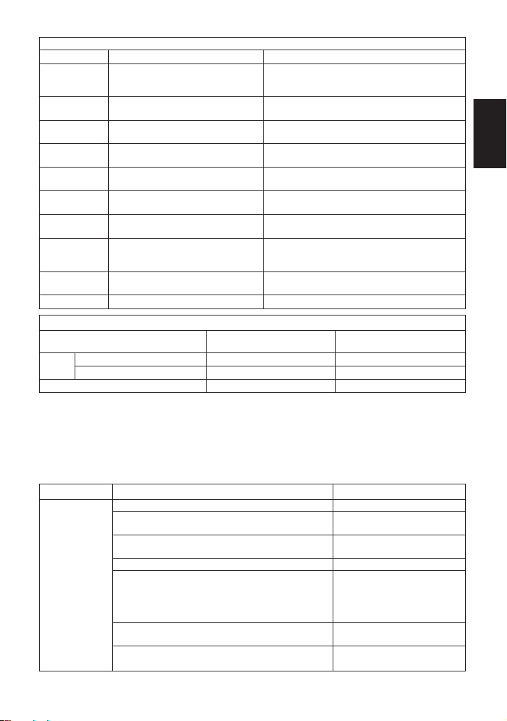
4.
Specifications Technische Daten Données techniques
Die Einbauhinweise beachten und die spezifizierten Betriebsgrenzen
NICHT ÜBERSCHREITEN. Nichtbeachtung kann zu Betriebsstörungen
oder Unfällen führen. Lokale Vorschriften können zur Unterschreitung der
angegebenen Werte zwingen.
VORSICHT
Installer le produit correctement et NE PAS l’utiliser en dehors des plages
spécifiées. En cas de dépassement des limites données, des dysfonctionnements ou accidents pourraient survenir. Il se peut que des
règlements locaux limitent l'utilisation du produit en-deçà des
spécifications indiquées.
ATTENTION
To avoid malfunctions, product damage, accidents or serious injury install
properly and, DO NOT use this product outside the specification range.
Local regulations may restrict the use of this product to below the
conditions quoted.
CAUTION
Refer to the product nameplate for detailed specifications.
Die technischen Daten stehen auf dem Typenschild.
Les données techniques sont inscrites sur la plaquette nominative.
* Maximum allowable pressure (PMA) and maximum allowable temperature (TMA) are
PRESSURE SHELL DESIGN CONDITIONS, NOT OPERATING CONDITIONS.
** Valve No. is displayed for products with options. This item is omitted from the nameplate
when there are no options.
Maximum Allowable Back Pressure: 80% of inlet pressure
Maximal zulässiger Gegendruck: 80% des Vordrucks
Contre-pression maximale : 80% de la pression amont
Minimum Operating Pressure: 0.03 MPaG (5 psig)
Minimaler Betriebsdruck: 0,3 bar ü
Pression de fonctionnement minimale : 0,3 bar
* Maximal zulässiger Druck (PMA) und maximal zulässige Temperatur (TMA) sind
AUSLEGUNGSDATEN, NICHT BETRIEBSDATEN.
** Die Valve No. wird angegeben bei Typen mit Optionen. Bei Typen ohne Optionen bleibt
diese Stelle frei.
* Pression maximale admissible (PMA) et Température maximale admissible (TMA) sont les
CONDITIONS DE CONCEPTION, PAS LES CONDITIONS DE FONCTIONNEMENT.
** Le Valve No. est indiqué sur les modèles avec options. Ce numéro ne figure pas sur les
modèles sans options.
Maximum Allowable Pressure*
Maximal zulässiger Druck*
Pression maximale admissible*
Maximum Operating Pressure
Maximaler Betriebsdruck
Pression de fonctionnement
maximale
Production Lot No.
Fertigungslos-Nr.
Lot de production n
。
Valve No.**
Nominal Diameter
Größe (DN)
Dimension (DN)
Maximum Operating
Temperature TMO
Maximale Betriebstemp. TMO
Temp. de fonctionnement maximale TMO
Maximum Allowable
Temperature* TMA
Maximal zulässige
Temperatur* TMA
Température maximale
admissible* TMA
Model
Typ
Modèle
7
Deutsch
Français
English
8
English
1.
Before installation, be sure to remove all protective seals.
2.
Before installing the trap, blow out the inlet piping to remove all dirt and oil.
3.
The trap can be installed either horizontally or vertically, but make sure the arrow on the trap
points in the direction of flow.
4.
Install the trap in the lowest part of the pipeline or equipment so that condensate flows naturally
into the trap by gravity. The inlet pipe should be as short and have as few bends as possible.
5.
Support the pipes properly within 800 mm (2.5 ft) on either side of the trap.
6.
Install a bypass valve to discharge condensate, and inlet and outlet valves to isolate the trap in
the event of trap failure or maintenance.
7.
Install a check valve at the trap outlet whenever more than one trap is connected to the
condensate collection pipeline.
8. In order to avoid excessive back pressure, make sure the discharge pipes are large enough;
(the outlet back pressure allowance should be no more than 80% of the inlet steam pressure).
9.
We recommend unions to facilitate connection and disconnection of the screwed version.
5. Proper Installation
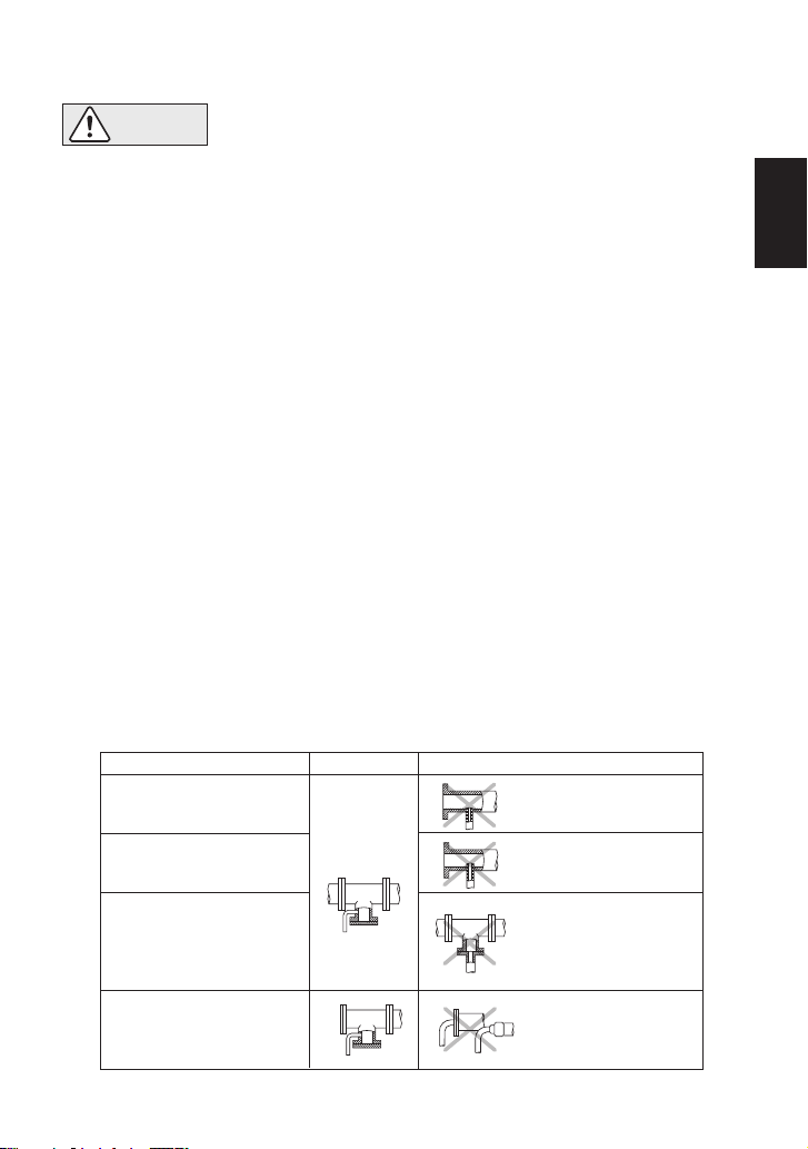
6. Piping Arrangement
Requirement
Diameter is too small.
Diameter is too small
and inlet protrudes
into pipe.
Rust and scale flow
into the trap with the
condensate.
Condensate collects
in the pipe.
Correct
Incorrect
Install a catchpot of the
proper diameter.
Make sure the flow of
condensate is not
obstructed.
To prevent rust and scale
from flowing into the trap,
connect the inlet pipe 25 50 mm (1 - 2 in) above the
base of the T-pipe.
When installing on the blind
end, make sure nothing
obstructs the flow of
condensate.
• Installation, inspection, maintenance, repairs, disassembly, adjustment
and valve opening/closing should be carried out only by trained
maintenance personnel.
• Take measures to prevent people from coming into direct contact with product outlets.
• Install for use under conditions in which no freeze-up will occur.
• Install for use under conditions in which no water hammer will occur.
NOTE: For socket weld connections, use electric welding with a single pass. As internal parts are
not damaged by a single welding pass
,
there is no need to remove them before welding.
CAUTION
Check to make sure that the pipes connected to the trap have been installed properly.
1. Is the pipe diameter suitable, and has sufficient space been secured for maintenance?
2. Has the trap been installed with the arrow on the body pointing in the direction of flow?
3. Have maintenance valves been installed at the inlet and outlet? If the outlet is subject to
back pressure, has a check valve been installed?
4. Is the inlet pipe as short as possible, with as few bends as possible, and installed so that the
condensate will flow naturally down into the trap?
5. Has the piping work been done correctly, as shown in the table below?

9
English
7. Operational Check
A visual inspection can be carried out to aid in determining the necessity for immediate
maintenance or repair, if the trap is open to atmosphere. If the trap does not discharge to
atmosphere, use diagnostic equipment such as TLV TrapMan or TLV Pocket TrapMan (within their
pressure and temperature measuring range).
(When conducting a visual inspection, flash steam is sometimes mistaken for steam leakage. For
this reason, the use of a steam trap diagnostic instrument such as TLV TrapMan is highly
recommended.)
Operational inspections should be performed at least twice per year, or as called for by trap
operating conditions. Steam trap failure may result in temperature drop in the equipment, poor
product quality or losses due to steam leakage.
Normal:
Condensate is discharged in a short blast followed by a longer period of no
drainage. During the discharge, flash steam may be seen. A small amount of flash
steam may be visible after the discharge.
Blocked:
(Discharge
Impossible)
No condensate is discharged. The trap is quiet and makes no noise. The surface
temperature of the trap is low.
Blowing: Live steam continually flows from the outlet, and there is a continuous metallic
sound.
Steam
Leakage:
Live steam is discharged through the trap outlet together with condensate,
accompanied by a high-pitched sound.
Chattering: The trap does not close properly. Steam is discharged from the trap in short rapid
bursts.
8. Inspection and Maintenance
• Installation, inspection, maintenance, repairs, disassembly, adjustment and
valve opening/closing should be carried out only by trained maintenance
personnel.
• Before attempting to open the trap, close the inlet and outlet isolating
valves and wait until the trap has cooled completely. Failure to do so may
result in burns.
• Be sure to use the proper components and NEVER attempt to modify the
product.
CAUTION
Body, Cover
Gaskets
Screen
Disc
Disc Holder Ring
Air Vent Ring
Module Valve Seat Surface
Check inside for damage, dirt, grease, oil film, rust or scale
Check for warping or damage
Check for clogging or corrosion
Check for damage or wear
Check for damage or wear
Check for damage or wear
Check for damage or wear
Parts Inspection Procedure
Flash Steam
White jet containing
water droplets
Clear, slightly
bluish jet
Live Steam Leakage
Part & No. During Disassembly
Disassembly / Reassembly (to reassemble, follow procedures in reverse)
During Reassembly
Cover 3
Air Vent Ring 6
Remove with a socket wrench
Remove without bending, as it
will not return to its proper shape
Coat threads with anti-seize; consult the
table of tightening torques and tighten to
the proper torque
Module Valve
Seat 2
Remove being careful not to
scratch the polished seat surface
Insert into the body levelly, being careful not
to tilt it or to scratch the seat surface
Reinsert without bending
Disc Holder
Ring 5
Remove without bending Set on the air vent ring and make sure that it
does not sit on the valve seat surface
Outer Module
Gasket 7
Remove only if worn or damaged;
clean the gasket housing
Replace with a new gasket if worn or
damaged
Screen Holder
Gasket 11
Remove gasket and clean sealing
surfaces
Replace with a new gasket, coat surfaces
with anti-seize
Screen 10
Remove without bending Reinsert without bending
Inner Module
Gasket 9
Remove only if worn or damaged;
clean the gasket housing
Replace with a new gasket if worn or
damaged
Screen
Holder 12
Remove with a socket wrench Coat threads with anti-seize; consult the
table of tightening torques and tighten to the
proper torque
Disc 4
Remove being careful not to
scratch the polished seat surface
Set on valve seat with the seat surface (the
lapped side) facing down toward the valve seat
9. Troubleshooting
If the expected performance is unachievable after installation of the trap, read chapter 5 and
chapter 6 again and check the following points for appropriate corrective measures.
Continued on next page
Problem Remedy
No condensate
is discharged
(blocked) or
discharge is
poor
Cause
Tightening Torque and Distance Across Flats
Part
Cover
P46SRN, P46SRM, P65SRN
P46SRW
Screen Holder
N·m (lbf·ft)
250
100
(185)
320
(235)
(73)
Torque
NOTE: - Coat all threaded portions with anti-seize.
- If drawings or other special documentation were supplied for the product,
any torque given there takes precedence over values shown here.
1 N·m
〜
〜
10 kg·cm
Screen is clogged with rust or scale
Disc is sticking to valve seat (due to oil, etc.)
Air vent ring (bimetal) is broken or worn, causing
air-binding
Clean
Clean
Replace air vent ring
Disc holder ring is broken or worn, causing airbinding
Replace disc holder ring
Steam-locking has occurred Perform a bypass blow-
down, or close the trap inlet
valve and allow the trap to
cool. Piping correction may
also be required.
Trap capacity is insufficient Change to trap of suitable
capacity
Differential pressure is low Study inlet/outlet pressure,
including rise in outlet pipe
mm (in)
46
30
(
1
)
55 (
2
)
(
1
)
Distance Across Flats
16
13
/
16
3
/
32
5
/
10
English

Problem RemedyCause
10. Optional Blowdown Valve BD2
Reassembly Type
1. Clean the trap, BD2 threads, and sealing surfaces, and apply a small amount of anti-seize.
2. Replace gasket.
3. Carefully place the gasket over the threaded portion, and position carefully so that it does not
become off-center.
4. Fasten to the steam trap with the proper torque.
BD2
Coat with
Anti-Seize
Torque (T) and Distance Across Flats (D)
32
21
/
(T): 30 N·m (22 lbf·ft)
(D): 17 mm ( ")
16
3
/
(T): 100 N·m (73 lbf·ft)
(D): 30 mm (1 ")
②
①
①
②
Steam leakage
or blowing
(from valve
seat)
Valve closure is obstructed by scale, etc. Clean or replace screen
Replace worn parts
Disc or valve seat is worn
Use within pressure rangeBack pressure exceeds allowable value
CleanDisc is sticking to top of cover (due to oil, etc.)
Trap is being used below minimum operating
pressure
Use within pressure range
Air vent ring (bimetal) or disc holder ring is
broken, obstructing valve closure
Replace air vent ring or disc
holder ring
Valve
chattering
(Leakage)
Leakage from a
location other
than valve seat
(via discharge,
or from
product body)
Foreign matter or oil film on disc or valve seat Clean
Cover is loose or module gaskets are
damaged
Tighten cover or replace
module gaskets
Tighten or replace cover, or
replace valve seat
Inlet and discharge channels may be
connected, due to erosion
Replace trap (study trap
capacity)
Screen holder is loose or screen holder
gasket is damaged
Tighten screen holder or
replace screen holder gasket
Cover is loose or sealing surface between cover
and valve seat is damaged
Scratches on disc or valve seat
Replace disc or valve seat
Disc or valve seat is worn Replace disc or valve seat
Bypass valve is damaged or open
Replace or close bypass valve
NOTE: When replacing parts with new, use the parts list on page 5 for reference, and replace with
parts from the appropriate kit. Please note that replacement parts are only available as part of a
replacement parts kit.
10.1 Reassembly of Blowdown Valve
The BD2 Blowdown Valve, installed in place of the screen holder, uses internal pressure to blow
out condensate/steam, dirt and scale to the atmosphere.
CAUTION
• Installation, inspection, maintenance, repairs, disassembly, adjustment
and valve opening/closing should be carried out only by trained
maintenance personnel.
• When disassembling or removing the product, wait until the internal pressure equals
atmospheric pressure and the surface of the product has cooled to room temperature.
• Do not tighten the BD2 valve or the BD2 valve seat in excess of the appropriate tightening
torque. Over-tightening may cause breakage to threaded portions, which may cause burns,
other injuries or damage.
11
English

11. Product Warranty
1) Warranty Period: one year after product delivery.
2) TLV CO., LTD. warrants this product to the original purchaser to be free from defective
materials and workmanship. Under this warranty, the product will be repaired or replaced at
our option, without charge for parts or labor.
3) This product warranty will not apply to cosmetic defects, nor to any product whose exterior
has been damaged or defaced; nor does it apply in the following cases:
1. Malfunction due to improper installation, use, handling, etc., by other than TLV CO., LTD.
authorized service representatives.
2. Malfunctions due to dirt, scale, rust, etc.
3. Malfunctions due to improper disassembly and reassembly, or inadequate inspection and
maintenance by other than TLV CO., LTD. authorized service representatives.
4. Malfunction due to disasters or forces of nature.
5. Accidents or malfunctions due to any other cause beyond the control of TLV CO., LTD.
4) Under no circumstances will TLV CO., LTD. be liable for consequential economic loss or
damage or consequential damage to property.
10.2 Operation Instructions for BD2
1. With two wrenches, firmly hold the BD2 Valve Seat (Screen Holder) ② (30 mm, 1 ") in place
while slowly opening the BD2 Valve ① (17 mm, ").
Be careful to avoid contact with fluid that will be discharged through the hole in the center of
the blowdown valve as the valve opens.
2. Close the BD2 Valve ① and tighten to a torque of 30 N·m (22 lbf·ft), and confirm that there is
no leakage. If leakage continues, dirt or scale may prevent the valve from sealing. Open and
blow out again, then try to close once more.
32
21
/
16
3
/
BD2 Valve ①
Screen Holder Gasket
Discharge Hole
Valve Stopper Pin
BD2 Valve Seat
(Screen Holder)
Screen
②
Note: Do not leave the vicinity while the blowdown valve is in the open position.
CAUTION
• Always wear eye protection and heat-resistant gloves when operating the
blowdown valve. Failure to do so may result in burns or other injury.
• When operating the blowdown valve, stand to the side well clear of the
outlet to avoid contact with internal fluids that will be discharged. Operate the valve slowly and
surely, taking care to avoid the area from which internal fluids are discharged and any fluids
deflected off piping or the ground etc. Failure to do so may result in burns or other injury.
• Do not excessively loosen the BD2 valve when opening the blowdown valve. The valve stopper
pin installed to prevent the BD2 valve from being removed may break and internal pressure may
result in the BD2 valve being blown off, leading to injuries, damage and fluid discharge, causing
burns.
12
English

13
Instructions for Plug / Holder Disassembly and Reassembly
The seal on the threaded plugs/holders found on TLV products is formed by a flat metal
gasket. There are various installation orientations for the gaskets, such as horizontal,
diagonal and downward, and the gasket may be pinched in the thread recesses during
assembly.
Instructions for Disassembly and Reassembly
① Remove the plug/holder using a tool of the specified
size (distance across flats).
② The gasket should not be reused. Be sure to
replace it with a new gasket.
③ Clean the gasket surfaces of the plug/holder and the
product body using a rag and/or cleaning agents, then
check to make sure the surfaces are not scratched or
deformed.
④ Coat both the gasket surface of the plug/holder and
the threads of the plug/holder with anti-seize, then
press the gasket onto the center of the gasket
surface of the plug/holder, making sure the
anti-seize affixes the gasket tightly to the
plug/holder. Check to make sure the gasket is not
caught in the recesses of the threads.
⑤ Hold the plug/holder upside down to make sure that
the anti-seize makes the gasket stick to the
plug/holder even when the plug/holder is held
upside down.
⑥ Screw the plug/holder by hand into the product body
while making sure that the gasket remains tightly
affixed to the center of the gasket surface of the
plug/holder. Make sure the entire gasket is making
contact with the gasket surface of the product body.
It is important at this point to make sure the gasket
is not pinched in the thread recesses of the
plug/holder.
⑦ Tighten the plug/holder to the proper torque.
⑧ Next, begin the supply of steam and check to make sure there is no leakage from the part
just tightened. If there is leakage, immediately close the inlet valve and, if there is a bypass
valve, take the necessary steps to release any residual pressure. After the surface of the
product cools to room temperature, repeat the procedure beginning from step①.
Gasket
Do not pinch gasket
in thread recesses
Coat with anti-seize
Gasket Surface
③
④
⑤
⑥
English

14
1.
Vor dem Einbau die Transport-Schutzkappen entfernen.
2.
Vor Einbau Leitung durchblasen, um Öl und Verschmutzungen zu entfernen.
3.
Der Kondensatableiter kann horizontal oder vertikal eingebaut werden, jedoch muss der Pfeil
auf dem Gehäuse in Durchflussrichtung zeigen.
4.
Die Zuführleitung sollte kurz sein, so wenige Krümmer wie möglich aufweisen, und ist so zu
verlegen, dass das Kondensat durch Schwerkraftwirkung dem KA zufließen kann.
5.
Die Kondensatleitung im Abstand von maximal 800 mm vor und hinter dem KA abstützen.
6.
Für Wartung und Inspektion Absperrorgane vor und hinter dem KA, sowie eine
Umgehungsleitung zur Notentwässerung vorsehen.
7.
Falls die Auslassleitung in einen Tank oder eine Kondensatrückführleitung mündet, oder falls
mehrere Kondensatableiter an eine gemeinsame Leitung angeschlossen sind, muss ein
Rückschlagventil hinter jedem Kondensatableiter eingebaut werden.
8. Zur Vermeidung von zu hohem Gegendruck die Rohrleitungen hinter dem KA gro
ß genug
dimensionieren. Der Gegendruck darf nicht höher als 80% des Vordrucks sein.
9.
Bei Muffenanschluss wird empfohlen, Rohrverschraubungen vor und hinter dem
Kondensatableiter anzubringen.
5. Einbauhinweise
6. Rohrleitungsführung
Vorschrift
Durchmesser zu klein.
Durchmesser zu klein
und Abflussrohr ragt in
Rohrleitung hinein.
Rost und sonstige
Ablagerungen
gelangen mit dem
Kondensat in den
Kondensatableiter.
Kondensat sammelt
sich in Rohrleitung an.
Richtig
Falsch
Kondensatstutzen mit ausreichendem Durchmesser
einbauen.
Für ungehinderten
Kondensatzufluss sorgen.
Um Rost und sonstige Ablagerungen vom KA fernzuhalten muss die Zuleitung
25 - 50 mm über dem
Deckel des Stutzens
angeschlossen werden.
Bei Einbau an Leitungsenden
ist die nebenstehende
Anschlussart vorzusehen,
damit das Kondensat ungehindert abfließen kann.
•
Einbau und Ausbau, Inspektion, Wartungs- und Reparaturarbeiten,
Öffnen/Schließen von Armaturen, Einstellung von Komponenten dürfen nur
von geschultem Wartungspersonal vorgenommen werden.
•
In sicherer Enfernung von Auslassöffnungen aufhalten und andere Personen warnen.
•
Kondensatableiter in frostsicherer Umgebung einbauen.
•
Kondensatableiter nur dort einbauen, wo kein Wasserschlag eintreten kann.
ANMERKUNG: Bei Schweißmuffenanschluss Elektroschweißung mit einlagiger Schweißnaht
anwenden. Die Innenteile brauchen dann wegen nur geringer Erwärmung nicht ausgebaut werden.
Stellen Sie sicher, dass die Rohrleitungsarbeiten richtig ausgeführt wurden und dass der
Kondensatableiter wie beschrieben, eingebaut wurde.
1. Ist die Nennweite groß genug und ist genügend Platz für Wartungsarbeiten vorhanden?
2. Wurde der Kondensatableiter mit dem Pfeil in Durchflussrichtung eingebaut?
3. Wurden vor und hinter dem Kondensatableiter Absperrarmaturen eingebaut? Falls
Gegendruck besteht: Wurde ein Rückschlagventil eingebaut?
4. Ist die Zuleitung so kurz wie möglich, hat sie so wenig Krümmer wie möglich und kann das
Kondensat durch Schwerkraft zufließen?
5. Wurden die Rohrleitungen so ausgeführt, wie unten beschrieben?
VORSICHT
Deutsch

15
7. Funktionsprüfung
Falls der Kondensatableiter das Kondensat ins Freie abführt, können visuelle Inspektionen einen
Hinweis geben, ob sofortige Wartung oder Reparatur notwendig ist. An Kondensatrückführleitungen
angeschlossene Kondensatableiter können mit geeigneten Messgeräten, z. B. TLV TrapMan oder
TLV Pocket TrapMan, innerhalb ihrer Druck- und Temperatur-Messbereiche geprüft werden.
(Bei visueller Inspektion wird oft Entspannungsdampf mit Dampfverlust verwechselt. Daher wird
empfohlen, im Zweifel Messgeräte, z. B. TLV TrapMan zu verwenden.)
Es wird empfohlen, mindestens zweimal pro Jahr, oder je nach Betriebsweise in kürzeren
Zeitabständen, eine Inspektion durchzuführen. Fehlerhafte Kondensatableiter führen zu
unerwünschten Dampfverlusten.
Normal:
Kondensat wird in kurzen schlagartigen Entladungen, unter Bildung von
Entspannungsdampf, gefolgt von längeren Perioden ohne Aktivität, abgeleitet.
Nach Beendigung der Ableitung kann noch eine geringe Menge von
Entspannungsdampf beobachtet werden.
Blockiert: Kondendsatabfluss nicht feststellbar. Der KA macht kein Geräusch und
seine Oberflächentemperatur ist niedrig.
KA bläst: Sattdampf tritt kontinuierlich an der Auslassseite aus und ein metallisch
klingendes Geräusch ist hörbar.
Dampfverlust: Sattdampf, vermischt mit Kondensat, tritt mit einem pfeifenden Geräusch
an der Auslassseite aus.
Ventilklappern: Der KA schließt nicht vollständig. Dampf tritt in kurzen schnell aufeinander
folgenden Stößen an der Auslassseite aus.
8. Inspektion und Wartung
• Einbau und Ausbau, Inspektion, Wartungs- und Reparaturarbeiten,
Öffnen/Schließen von Armaturen, Einstellung von Komponenten dürfen nur
von geschultem Wartungspersonal vorgenommen werden.
• Vor dem Öffnen des Kondensatableiters sind die Absperrarmaturen auf
beiden Seiten zu schließen. Gehäuse auf Raumtemperatur abkühlen
lassen. Nichtbeachtung kann zu Verbrennungen führen.
• Zur Reparatur nur Original-Ersatzteile verwenden und NICHT
VERSUCHEN; das Produkt zu verändern.
Entspannungsdampf
Weißer
Strahl mit
Wassertröpfchen
Klarer, leicht
bläulicher Strahl
Dampfverlust
VORSICHT
Gehäuse, Deckel
Dichtungen
Schmutzsieb
Ventilteller
Ventilteller-Haltering
Entlüftungsring
Ventilsitzgarnitur
Auf Ablagerungen, Rost, Schmutz, Ölfilm prüfen.
Auf Verformung oder Beschädigung prüfen.
Auf Verstopfung, Ablagerungen, Beschädigung prüfen.
Auf Beschädigung oder Verschleiß prüfen.
Auf Beschädigung oder Verschleiß prüfen.
Auf Beschädigung oder Verschleiß prüfen.
Dichtflächen auf Beschädigung oder Verschleiß prüfen.
Überprüfung der Einzelteile
Deutsch

Symptom Gegenmaßnahmen
Kondensat läuft
nicht ab
(blockiert), oder
Ableitung ist
ungenügend
9. Fehlersuche
Falls der Kondensatableiter nicht zufriedenstellend arbeitet, lesen Sie nochmals Kapitel 5 und Kapitel
6. Gehen sie dann die nachfolgende Fehlerliste durch, um den Fehler zu orten und zu korrigieren.
Ursachen
Fortsetzung nächste Seite
Bauteil & Nr. Ausbau
Ausbau und Einbau der Teile (Einbau erfolgt in umgekehrter Reihenfolge)
Einbau
Verschlusskappe 3
Entlüftungsring 6
Mit Sechskantschlüssel
abschrauben.
Abheben ohne zu verbiegen, da
er nicht in seine ursprüngliche
Form zurückkehrt.
Gewinde mit Schmiermittel versehen,
aufsetzen und mit vorgeschriebenem
Anzugsmoment anziehen.
Ventilsitzgarnitur 2
Abheben, dabei die geläppte
Ventilsitzfläche nicht zerkratzen.
Senkrecht einsetzen, nicht schräg
halten, Ventilsitzfläche nicht zerkratzen.
Einsetzen ohne zu verbiegen.
VentiltellerHaltering 5
Abheben ohne zu verbiegen. Auf den Entlüftungsring setzen und
darauf achten, dass er nicht auf der
Ventilsitzoberfläche aufsitzt.
Äußere Ventilsitzdichtung 7
Dichtung nur abnehmen, falls verformt
oder beschädigt; Dichtungsrille reinigen.
Dichtung nur erneuern, falls verformt
oder beschädigt.
Dichtung Siebhaltestopfen 11
Dichtung abnehmen und
Dichtflächen reinigen.
Dichtung erneuern, Dichtflächen mit
Schmiermittel bestreichen.
Schmutzsieb 10
Vorsichtig herausheben, dabei
nicht verbiegen.
Vorsichtig einsetzen, dabei nicht
verbiegen.
Innere Ventilsitzdichtung 9
Dichtung nur abnehmen, falls verformt
oder beschädigt; Dichtungsrille reinigen.
Dichtung nur erneuern, falls verformt
oder beschädigt.
Siebhaltestopfen 12
Mit Sechskantschlüssel
abschrauben.
Gewinde mit Schmiermittel versehen
und mit vorgeschriebenem
Anzugsmoment anziehen.
Ventilteller 4
Abheben, dabei die geläppte
Oberfläche nicht zerkratzen.
Ventilteller so aufsetzen, dass die
geläppte Fläche nach unten zeigt.
Anzugsmoment und Schlüsselweite
Bauteil
Verschlusskappe
Siebhaltestopfen
P46SRN, P46SRM, P65SRN
P46SRW
Anzugsmoment
N·m
250
320
100
Schlüsselweite
mm
46
55
30
ANMERKUNG: - Alle Schraubengewinde mit geeignetem Schmiermittel bestreichen.
- Falls Zeichnungen oder andere Dokumente mit dem Produkt geliefert wurden, haben Angaben
über Anzugsmomente in diesen Unterlagen Vorrang vor den hier gezeigten Anzugsmomenten.
Schmutzsieb ist verstopft mit Rost oder
Ablagerungen
Reinigen
Umgehungsleitung durchblasen
oder Einlassventil schließen und
Kondensatableiter abkühlen lassen.
Rohrleitungsführung überprüfen
und ggf. korrigieren.
Dampfabschluss ist eingetreten.
KA mit größerer Leistung einsetzenDurchsatzleistung des KA ist zu gering
ReinigenVentilteller klebt an Ventilsitz (Öl o. ä.)
Ventilteller-Haltering ist gebrochen oder
beschädigt, daher Luftabschluss
Ventilteller-Haltering ersetzen
Entlüftungsring (Bimetall) ist gebrochen
oder beschädigt, daher Luftabschluss
Entlüftungsring ersetzen
Differenzdruck ist ungenügend Einlass/Auslassdruck überprüfen,
(Anstieg der Auslassleitung?)
16
Deutsch

Symptom Gegenmaßnahmen
KA bläst Dampf
ab (über
Ventilsitz)
Ursachen
Ventil kann nicht schließen wegen
Schmutzablagerungen
Reinigen oder Schmutzsieb
ersetzen
Ventilteller oder Ventilsitz verschlissen Ventilteller oder Ventilsitz ersetzen
Ventilteller verschmutzt (durch Öl etc.) Reinigen
Gegendruck übersteigt zulässige Höhe Zulässigen Gegendruck beachten
Entlüftungsring (Bimetall) oder VentiltellerHaltering ist gebrochen und verhindert
Schließen des Ventils
Entlüftungsring oder VentiltellerHaltering ersetzen
Verschlusskappe ist lose oder
Ventilsitzdichtungen sind beschädigt
Verschlusskappe fest anziehen
oder Ventilsitzdichtungen ersetzen
Verschlusskappe ist lose oder Dichtfläche
zwischen Verschlusskappe und Ventilsitz
ist beschädigt
Verschlusskappe fest anziehen
oder ersetzen, oder Ventilsitz
ersetzen
ANMERKUNG: Wenn Bauteile ersetzt werden müssen, benutzen Sie die Bauteilliste auf Seite 5
und ersetzen Sie die beschädigten Teile aus dem entsprechenden Bauteil-Satz. Ersatzteile
werden nicht einzeln, sondern als Teil dieser Bauteil-Sätze geliefert.
Ventilteller
klappert
(Dampfverlust)
Dampfverlust an
anderen Stellen
(Leckage am
Gehäuse oder
hinter Ventilsitz)
Kratzer auf Ventilteller oder Ventilsitz Ventilteller oder Ventilsitz ersetzen
Ventilteller oder Ventilsitz verschlissen Ventilteller oder Ventilsitz ersetzen
KA wird bei Druck unter zulässigem
Mindestdruck betrieben
Zulässigen Mindestdruck
beachten
Verbindung zwischen Einlass und Auslass
durch Erosion
Kondensatableiter ersetzen
(Durchsatzleistung überprüfen)
Siebhaltestopfen ist lose oder
Stopfendichtung ist beschädigt
Siebhaltestopfen fest anziehen
oder Dichtungen ersetzen
Armatur in Umgehungsleitung leckt oder
steht offen
Reparieren oder absperren
Ventiteller klebt an Verschlußkappe Reinigen
10. Ausblaseventil BD2 (Option)
Zusammenbau
1. BD2 Gewinde und Dichtflächen Kondensatableiter reinigen und mit einer kleinen Menge
Schmiermittel versehen.
2. Dichtung ersetzen.
3. Die Dichtung bzw. Dichtungen im Fall von BD2 und Siebhaltestopfensatz über das Gewinde
führen und darauf achten, dass sie konzentrisch aufliegt, bzw. aufliegen.
4. Mit den unten aufgeführten Anzugsmomenten anziehen.
BD2
Mit Schmiermittel
bestreichen
Anzugsmomente (A) und Schlüsselweiten (S)
(A): 30 N
·m
(S): 17 mm
(A): 100 N
·m
(S): 30 mm
②
①
①
②
10.1 Zusammenbau des Ausblaseventils
Das an der Stelle des Siebhalters installierte Ausblaseventil BD2 benutzt Innendruck zum
Ausblasen von Kondensat/Dampf und darin enthaltenen Verunreinigungen in die Atmosphäre.
• Einbau und Ausbau, Inspektion, Wartungs- und Reparaturarbeiten,
Öffnen/Schließen von Armaturen, Einstellung von Komponenten dürfen
nur von geschultem Wartungspersonal vorgenommen werden.
• Vor Öffnen des Gehäuses und Ausbau von Teilen warten, bis der Innendruck sich auf
Atmosphärendruck gesenkt hat und das Gehäuse auf Raumtemperatur abgekühlt ist.
Nichtbeachtung kann zu Verbrennungen oder Verletzungen durch austretende Fluide führen.
• Das BD2-Ventil und den BD2-Ventilsitz nicht stärker als mit den angegebenen
Anzugsmomenten festziehen. Die Gewinde können sonst Schaden nehmen, was zu
Verbrennungen, anderen Verletzungen und Schäden führen kann.
VORSICHT
17
Deutsch

11. Garantie
1) Garantiezeit: Ein Jahr nach Lieferung.
2) Falls das Produkt innerhalb der Garantiezeit, aus Gründen, die TLV CO., LTD. zu vertreten
hat, nicht der Spezifikation entsprechend arbeitet, oder Fehler an Material oder Verarbeitung
aufweist, wird es kostenlos ersetzt oder repariert.
3) Von der Produktgarantie ausgenommen sind kosmetische Mängel sowie Beschädigungen
des Produktäußeren. Die Garantie erlischt außerdem in den folgenden Fällen:
1. Schäden, die durch falschen Einbau oder falsche Bedienung hervorgerufen werden.
2. Schäden, die durch Verschmutzungen, Ablagerungen oder Korrosion usw. auftreten.
3. Schäden, die durch falsches Auseinandernehmen, falschen Zusammenbau oder
ungenügende Inspektion und Wartung entstehen.
4. Schäden verursacht durch Naturkatastrophen und Unglücksfälle.
5. Unglücksfälle und Schäden aus anderen Gründen, die von TLV CO., LTD. nicht zu
vertreten sind.
4) TLV CO., LTD. haftet nicht für Folgeschäden.
10.2 Betriebsanleitung für das Ausblaseventil BD2
Ausblaseventil BD2 ①
Dichtung Siebhaltestopfen
Auslassöffnung
Haltestift
Ventilsitz BD2
(Siebhaltestopfen)
Schmutzsieb
②
1. Zum Öffnen des Ventils zwei Schraubenschlüssel benutzen: Einen, um den BD2 Ventilsitz
(Siebhaltestopfen) ② (30 mm) sicher zu halten, den anderen, um langsam das Ausblaseventil
BD2 ① (17 mm) zu öffnen. Nicht mit dem aus der Ausblaseöffnung ausströmenden Fluid in
Berührung kommen.
2. Das Ausblaseventil BD2 ① schließen und mit einem Anzugsmoment von 30 N·m anziehen.
Nach dem Schließen vergewissern, dass kein Fluid austritt. Falls Fluid austritt, ist das ein
Zeichen, dass Schmutz und Ablagerungen am Ventilsitz das vollständige Schließen verhindern.
Wieder öffnen, ausblasen und schließen.
Anmerkung: Den Arbeitsplatz nicht verlassen, solange das Ventil in offener Stellung steht.
• Bei Gebrauch von BD2 werden Schutzbrille und isolierte, hitzebeständige
Handschuhe dringend empfohlen. Nichtbeachtung kann zu
Verbrennungen oder anderen Verletzungen führen.
• Bei Gebrauch des Ausblaseventils immer seitlich in sicherem Abstand vom Austritt stehen, um
Kontakt mit den austretenden Fluiden zu vermeiden. Das Ventil behutsam bedienen, und dabei
Acht geben, nicht in den Austrittsbereich von Fluiden, insbesondere deren Ablenkungen an
Leitungen und anderen Gegenständen, zu geraten. Nichtbeachtung kann zu Verbrennungen
oder Verletzungen führen.
• Beim Öffnen des Ausblaseventils das BD2-Ventil nicht übermäßig öffnen. Der Ventilhaltestift
könnte sonst brechen und das BD2-Ventil sich durch den Inenndruck schlagartig lösen, was zu
Verletzungen, Schäden und Verbrennungen durch austretende Fluide führen kann.
VORSICHT
18
Deutsch

Aus- und Einbau-Anleitung für Entwässerungsstopfen
Die Gewindedichtung der Entwässerungsstopfen an TLV-Kondensatableitern besteht aus
einem flachen Metallring. Stopfen und Dichtung können in verschiedenen Lagen eingebaut
werden - horizontal, diagonal oder nach unten zeigend. Wird der Metallring dabei im
Gewinde gequetscht, verliert er seine Funktionstüchtigkeit.
Ausbau und Einbau
① Den Entwässerungsstopfen mit einem
Ringschlüssel gemäß der angegeben
Schlüsselweite ausschrauben.
② Einmal eingebaute Dichtungen nicht
wiederverwenden, sondern unbedingt ersetzen.
③ Die Dichtflächen am Entwässerungsstopfen und am
Kondensatableiter mit einem Lappen o.ä. säubern
und auf einwandfreien Zustand prüfen (Kratzer).
④ Sowohl die Dichtfläche, als auch das Gewinde
des Entwässerungsstopfens mit Schmiermittel
bestreichen. Dann den Dichtring zentriert auf die
Dichtfläche des Stopfens bringen, sodass der
Ring aufgrund des Schmiermittels am Stopfen
haftet. Der Dichtring darf nicht in eine
Gewindevertiefung verrutschen.
⑤ Den Entwässerungsstopfen zur Probe der
Haftung des Dichtringes nach unten richten.
⑥ Den Entwässerungsstopfen per Hand in den
Kondensatableiter eindrehen und dabei darauf
achten, dass der Dichtring zentriert auf der
Dichtfläche des Stopfens bleibt. Darauf achten,
dass der Dichtring nicht in das Gewinde
verrutscht, besonders wenn der Dichtring Kontakt
auch mit der Dichtfläche des Kondensatableiters
bekommt.
⑦ Den Entwässerungsstopfen mit dem
ausgewiesenen Drehmoment festziehen.
⑧ Führen Sie als nächstes eine Dichtigkeitsprüfung unter Dampf vor und achten besonders
auf das soeben eingebaute Bauteil. Falls Leckage auftritt sofort die Absperrarmatur an der
Einlassseite schließen und den Restdruck ablassen, falls eine Umgehungsleitung installiert
ist. Nach dem Ausgleich mit dem Umgebungsdruck und dem Abkühlen der
Produktoberflächen auf Raumtemperatur Aus- und Einbau ab ①wiederholen.
Dichtfläche
Dichtung
Dichtung nicht in das
Gewinde bringen
Mit Schmiermittel
versehen
③
④
⑤
⑥
Deutsch
19

1.
Ne pas oublier d'ôter toutes les étiquettes protectrices avant l'installation.
2.
Avant l'installation, souffler la tuyauterie d'entrée afin d'en retirer l'huile et les saletés.
3.
Le purgeur peut être installé horizontalement ou verticalement, mais vérifier que la flèche sur le
corps pointe dans le sens du flux du condensât.
4.
Placer le purgeur de façon à ce que le condensât entre dans le purgeur par gravité. La
conduite d'entrée devrait être la plus courte et la moins courbée possible.
5.
Prévoir des supports de conduite à 0,8 m de chaque côté du purgeur.
6.
Installer des robinets d’isolement ainsi qu’un robinet de by-pass (ou de mise à l’atmosphère)
pour intervenir sur un purgeur (réparation ou entretien).
7.
Installer un clapet de retenue à la sortie du purgeur quand plusieurs purgeurs sont raccordés à
la conduite de collecte des condensats.
8. Afin d'
éviter une contre-pression excessive, s'assurer que les conduites d'évacuation sont
suffisamment grandes (la contre-pression à la sortie du purgeur ne devrait pas excéder 80% de
la pression amont).
9.
L'utilisation de raccords est recommandée pour faciliter la connexion et la déconnexion de
la version taraudée.
5. Installation correcte
6. Disposition des conduites
• Tout installation, inspection, entretien, réparation, démontage, réglage
et ouverture/fermeture de vanne doit être fait uniquement par une
personne formée à l’entretien.
• Éviter que des personnes n'entrent en contact direct avec les ouvertures du produit.
• Utiliser le purgeur dans des conditions où le gel ne se produit pas.
• Ne pas utiliser le purgeur dans des conditions où des coups de bélier peuvent se produire.
NOTE : Pour les raccordements à douille, utiliser une soudure à l'arc électrique avec passage
unique. Les pièces internes ne sont pas endommagées par ce type de soudure.
Vérifier que les conduites raccordées au purgeur aient été installées correctement.
1. Le diamètre de la conduite est-il adéquat ?
2. Le purgeur a-t-il été installé avec la flèche sur le corps pointant dans le sens du flux ?
3. Des vannes pour l'entretien ont t-elles été installées à l’entrée et à la sortie ? Si la sortie est
sujette à contre-pression, un clapet de retenue a t-il été installé ?
4. La conduite d’entrée est-elle la plus courte et avec moins de coude possible de façon à ce
que le condensât s'écoule par gravité ?
5. La tuyauterie a-t-elle été réalisée correctement, tel qu’illustré dans le tableau ci-dessous ?
ATTENTION
Condition requise
Diamètre trop petit.
Diamètre trop petit et
l'entrée fait saillie
dans la conduite.
De la rouille et des
résidus pénètrent le
purgeur avec le
condensat.
Le condensât
s'accumule dans la
conduite.
Correct
Incorrect
Installer un pot de purge d'un
diamètre adéquat.
Vérifier que le flux de
condensât n'est pas obstrué.
Pour empêcher l'entrée de
rouille et de résidu dans le
purgeur, connecter le tuyau
d'entrée 25-50 mm audessus de la base du tuyau
en T.
Lorsque le purgeur est
installé en bout de conduite,
vérifier que rien n'obstrue
le flux de condensât.
20
Français

7. Vérification de fonctionnement
Une inspection visuelle permet de déterminer si un entretien ou une réparation immédiate sont
nécessaires au cas où le purgeur est ouvert à l'atmosphère. Utiliser du matériel de diagnostic,
comme le TLV TrapMan ou le TLV Pocket TrapMan (en respectant les limites de pression et de
température indiquées pour la mesure), si le condensât n'est pas évacué dans l'atmosphère.
(Lors d'une inspection visuelle, il est facile de confondre la présence de vapeur de revaporisation
avec une fuite de vapeur. Pour cette raison, l'utilisation d'un appareil de diagnostic comme le TLV
TrapMan est fortement recommandée.)
Des inspections périodiques devraient être faites au moins deux fois par an, ou bien aux
intervalles habituels. Un purgeur de vapeur défectueux peut être à l'origine de fuites de vapeur.
Fonctionnement
normal :
Le condensât est expulsé d'un seul souffle court, suivi d'une période plus longue
sans expulsion. Pendant l'expulsion, de la vapeur de revaporisation devrait être
visible. Après l'expulsion, une petite quantité de vapeur de revaporisation peut
encore être visible.
Bloqué : Pas d'évacuation du condensât. Le purgeur ne fait pas de bruit et la température
de sa surface est basse.
Grosse
fuite :
De la vapeur vive s'écoule continuellement par la sortie tout en faisant un bruit
métallique continu.
Fuite de
vapeur :
De la vapeur vive est évacuée du purgeur avec le condensât tout en émettant
strident.
Broutage : Le purgeur ne se ferme pas convenablement. La vapeur est expulsée du purgeur
par poussées brèves et rapides.
8. Contrôle et entretien
• Tout installation, inspection, entretien, réparation, démontage, réglage
et ouverture/fermeture de vanne doit être fait uniquement par une
personne formée à l’entretien.
• Avant de vouloir ouvrir le purgeur, fermer les soupapes de sectionnement
à l'entrée et à la sortie du purgeur, et attendre qu'il soit complètement
refroidi. Le non-respect de ces consignes peut être à l'origine de brûlures.
• Utiliser les pièces recommandées et NE JAMAIS modifier le purgeur.
Corps, couvercle
Joints
Crépine
Disque
Anneau support du disque
Anneau purge d'air
Surface module siège de soupape
Vérifier qu'il n'y ait pas de saletés, de graisse, de
pellicule d'huile, de rouille ou de résidu à l'intérieur
Vérifier qu'ils ne soient ni gondolés ni endommagés
Vérifier qu'elle ne soit ni encrassée, ni corrodée, ni
endommagée
Vérifier qu'il n'y ait pas d'endommagement ou d'usure
Vérifier qu'il n'y ait pas d'endommagement ou d'usure
Vérifier qu'il n'y ait pas d'endommagement ou d'usure
Vérifier qu'il n'y ait pas d'endommagement ou d'usure
Procédure d'inspection des pièces
Vapeur de
revaporisation
Jet blanc
contenant des
gouttelettes
d'eau
Jet clair et
bleuâtre
Fuite de
vapeur vive
ATTENTION
21
Français

Problèmes Remèdes
Peu ou
pas de
purge de
condensât
(bloqué)
9. Détection des problèmes
Si le fonctionnement du produit n'est pas satisfaisant, consulter les parties 5 et 6 à nouveau, et
vérifier les points suivants :
Causes
Suite à la page suivante
Pièce et n° Pendant le démontage
Retrait et remplacement des pièces (suivre I'ordre inverse pour le remontage)
Pendant le remontage
Couvercle 3
Anneau purgeur
d’air 6
Retirer avec une clé à douille
Retirer sans le plier, sinon il ne
reprendrait pas sa forme initiale
Enduire le pas de vis d’anti-grippant;
consulter le tableau des couples de
serrage puis serrer avec le couple de
serrage adéquat
Module siège
de soupape 2
Retirer le module, tout en faisant
attention de ne pas rayer la
surface rodée
Insérer dans le corps de façon
équilibrée, sans le faire pencher et sans
rayer la surface du siège
Insérer l’anneau sans le plier
Anneau support
disque 5
Retirer l’anneau sans le plier Placer sur l'anneau purge d'air, et
vérifier qu'il ne repose pas sur la
surface du siège de soupape
Joint module
externe 7
Retirer uniquement si usé ou
endommagé; nettoyer le boîtier du joint
Si le joint est usé ou endommagé,
remplacer par un nouveau joint
Joint de portecrépine 11
Retirer et nettoyer les surfaces
d'étanchéité
Remplacer par un nouveau joint,
appliquer de l’anti-grippant aux
surfaces d'étanchéité
Crépine 10 Retirer sans la plier Insérer sans la plier
Joint module
interne 9
Retirer uniquement si usé ou
endommagé; nettoyer le boîtier du joint
Si le joint est usé ou endommagé,
remplacer par un nouveau joint
Porte-crépine 12 Retirer avec une clé à douille Enduire le pas de vis d’anti-grippant;
consulter le tableau des couples de
serrage puis serrer avec le couple de
serrage adéquat
Disque 4 Retirer le disque, tout en faisant
attention de ne pas rayer la
surface rodée
Placer sur le siège de soupape avec la
surface du siège (le côté rodé) vers le
bas, en direction du siège
Couples de serrage et ouvertures de clé
Pièce
Couvercle
Porte-crépine
P46SRN, P46SRM, P65SRN
P46SRW
Serrage
N·m
250
320
100
Ouverture de clé
mm
46
55
30
NOTE : - Appliquer de l’anti-grippant sur toutes les portions filetées.
- Si des dessins ou autres documents spéciaux ont été fournis pour le produit, les couples de
serrage donnés dans ces documents doivent être pris en compte plutôt que les valeurs données ici.
Crépine encrassée de rouilles et de résidus
L'anneau bimétallique est cassé ou usé,
causant l'obstruction par l'air
Nettoyer
Remplacer l'anneau
L'anneau support du disque est cassé ou usé,
causant l'obstruction par l'air
Remplacer l'anneau
Le disque colle au siège de soupape (à cause
d'huile, etc..)
Nettoyer
Bouchon de vapeur
La capacité du purgeur est insuffisante
Faire une purge by-pass, ou fermer la
soupape d'entrée du purgeur afin de
laisser le purgeur se refroidir. Modif. de
la tuyauterie peut être nécessaire.
Remplacer par un purgeur de
capacité supérieure
Pression différentielle insuffisante
Analyser les pressions amont et
aval, y compris la montée dans la
conduite de sortie
Français
22

Problèmes Remèdes
Fuites de
vapeur (du
siège de
soupape)
Broutage
(fuite)
Fuite en
provenance
d'une partie
autre que le
siège de
soupape
Causes
Des dépôts ou des résidus obstruent la
fermeture de la soupape
Nettoyer ou remplacer la crépine
L'anneau bimétallique ou l'anneau support du
disque est cassé et obstrue la fermeture de la
soupape
Remplacer l'anneau bimétallique
ou l'anneau support du disque
Contre-pression excessive
Respecter les spécifications données
Respecter les spécifications
données
Le purgeur est utilisé en-dessous de la
pression de fonctionnement minimale
Remplacer le disque, ou le siège
de soupape
Rayures au disque ou au siège de soupape
Remplacer le disque, ou le siège
de soupape
Le disque ou le siège de soupape est usé
NettoyerAccumulation de dépôts ou d'huile sur le
disque ou le siège de soupape
Le disque ou le siège de soupape est usé Remplacer les pièces usées
Le couvercle est lâche ou les joints de module
sont endommagés
Resserrer le couvercle ou
remplacer les joints de module
Les conduites d'entrée et d'évacuation sont
reliées suite à l'érosion
Remplacer le purgeur (analyser la
capacité du purgeur)
Le bouchon porte-crépine est lâche ou le joint
porte-crépine est endommagé
Resserrer le bouchon portecrépine ou remplacer le joint
La soupape by-pass est endommagée ou ouverte
Remplacer ou fermer la soupape
Le couvercle est lâche ou la surface
d'étanchéité entre le couvercle et le siège de
soupape est endommagée
Resserrer ou remplacer le couvercle,
ou remplacer le siège de soupape
Le disque colle au couvercle (à cause d'huile, etc...)
Nettoyer
NOTE : Lors du remplacement de pièces, se référer à la liste de pièces à la page 5 et remplacer
par des pièces du jeu de pièces approprié. Les pièces de rechange sont uniquement disponibles
sous la forme de jeux de pièces.
1. Nettoyer le purgeur, la surface filetée du BD2, ainsi que les surfaces d'étanchéité, et y
appliquer une petite quantité d'anti-grippant.
2. Remplacer le joint.
3. Placer soigneusement le joint par-dessus la partie filetée et le positionner avec précision pour
éviter qu'il ne se décentre.
4. L'attacher au purgeur avec le couple de serrage adéquat.
10. Robinet de purge BD2 (optionnel)
Remontage
BD2
Enduire
d'anti-grippant
Couples de serrage (C) et ouvertures de clé (O)
(C): 30 N
·m
(O): 17 mm
(C): 100 N
·m
(O): 30 mm
②
①
①
②
10.1 Remontage du robinet de purge BD2
Le robinet de purge BD2, installé à place du porte-crépine, utilise la pression interne pour expulser
le condensât/la vapeur ainsi que des résidus et des poussières vers l'atmosphère.
• Tout installation, inspection, entretien, réparation, démontage,
réglage et ouverture/fermeture de vanne doit être fait uniquement
par une personne formée à l’entretien.
• En cas de démontage ou de retrait du produit, attendre que la pression interne soit égale à la
pression atmosphérique et que la surface du produit ait atteint la température ambiante.
• Ne pas fermer la vanne BD2 ou le siège de vanne BD2 avec une force supérieure au couple de
serrage adéquat. Cela pourrait provoquer la détérioraton de parties du filet, et ainsi causer des
brûlures, autres blessures ou dégâts.
ATTENTION
23
Français

11. Garantie
1) Durée de la garantie : un an à partir de la livraison du produit.
2) Champ d’application de la garantie : TLV CO., LTD. garantit à l’acheteur originel que ce
produit est exempt de tout vice de fabrication ou de qualité du matériau. Sous cette
garantie, le produit sera réparé ou remplacé, au choix de TLV CO. LTD., sans aucun frais de
pièces ou de main d’œuvre.
3) Cette garantie ne s’applique pas aux défauts d’apparence ni aux produits dont l’extérieur a
été endommagé ou altéré. Elle ne s’applique pas non plus dans les cas suivants :
1. Dysfonctionnements dus à toute installation, utilisation ou maniement incorrect par un
agent de service autre que ceux agréés par TLV CO., LTD.
2. Dysfonctionnements attribuables aux saletés, dépôts, rouille, etc.
3. Dysfonctionnements dus à un démontage et/ou à un remontage incorrect, ou à tout
contrôle ou entretien inapproprié, par un agent autre que ceux agréés par TLV CO., LTD.
4. Dysfonctionnements dus à tout désastre ou catastrophe naturelle.
5. Accidents ou dysfonctionnements dus à toute autre cause échappant au contrôle de
TLV CO., LTD.
4) En aucun cas, TLV CO., LTD. ne sera tenu responsable de pertes économiques éventuelles
ou de dommages matériels qui pourraient découler d’un tel défaut.
10.2 Fonctionnement du robinet de purge BD2
Soupape de purge BD2 ①
Joint porte-crépine
Trou d'expulsion
Goupille d'arrêt
Siège de Soupape BD2
(Porte-crépine)
Crépine
②
1. Utiliser deux clés à vis - l’une pour tenir fermement le siège du BD2 (bouchon de porte-crépine)
② (30 mm), l’autre pour ouvrir lentement la soupape de purge BD2 ① (17 mm). Faire attention
d'éviter tout contact avec le fluide expulsé par le trou au centre de la soupape de purge
lorsque celle-ci s'ouvre.
2. Fermer la soupape de purge BD2, la resserrer avec un couple de serrage de 30 N·m et vérifier
qu'il n'y a pas de fuite. Si une fuite persiste, il se peut que des poussières ou des résidus
gênent l'étanchéité de la soupape. Ouvrir et expulser à nouveau, puis essayer de fermer
à nouveau.
Note : Ne pas s'éloigner du robinet de purge lorsque celui-ci est en position ouverte.
• Toujours se protéger les yeux et porter des gants résistant à la chaleur
pour manipuler le robinet de purge. Le non-respect de cette règle peut
provoquer des brûlures ou autres blessures.
• Lorsque le robinet de purge fonctionne, se tenir bien à l’écart de l’orifice afin d’éviter tout
contact avec les fluides internes qui sont expulsés. Ouvrir la vanne progressivement et en
sécurité, en faisant attention aux endroits où les fluides internes sont expulsés et qui
pourraient gicler sur les tuyauteries ou sur le sol. Le non-respect de cette règle peut provoquer
des brûlures ou autres blessures.
• Ne pas trop desserrer le robinet de purge BD2 en l'ouvrant. La goupille d’arrêt de siège de
soupape installée pour éviter que la vanne BD2 ne soit retirée pourrait casser et la pression
interne provoquerait alors l'expulsion du BD2. Ceci causerait d'éventuelles blessures, des
dégât ou encore des brûlures par le fluide déchargé.
ATTENTION
24
Français

Instructions pour le démontage/remontage du bouchon/support
Le dispositif d’étanchéité des bouchons/supports filetés compris dans les produits TLV est
constitué d’un joint en métal plat. Les joints peuvent être orientés différemment
(horizontalement, diagonalement, vers le bas), et ils peuvent se bloquer dans la saignée du
filet au cours de l’assemblage.
Instructions de démontage et de remontage
① Retirer le bouchon/support au moyen d’un outil de
taille adéquate (ouverture de clé).
② Le joint ne doit pas être réutilisé. Veillez à le
remplacer par un nouveau joint.
③ Nettoyer les surfaces du joint du bouchon/support et
le corps du produit au moyen d’un chiffon et/ou de
nettoyants, puis vérifier si les surfaces ne sont pas
rayées ou déformées.
④ Enduire la surface du joint du bouchon/support et les
filets du bouchon/support d’anti-grippant. Presser
ensuite le joint contre le centre de la surface du joint,
en veillant à ce que l’anti-grippant fixe le joint contre
le bouchon/support. Veiller à ce que le joint ne soit
pas pris dans la saignée du filet.
⑤ Tenir le bouchon/support à l’envers pour être sûr
que l’anti-grippant fasse coller le joint au
bouchon/support, même en tenant ce dernier à
l’envers.
⑥ Visser manuellement le bouchon/support dans le
corps du produit tout en veillant à ce que le joint
demeure fixé au centre de la surface du joint du
bouchon/support. Veiller à ce que le joint entier soit
en contact avec la surface du joint du corps du
produit. Il est important de surveiller ici que le joint
ne soit pas bloqué dans la saignée du filet du
bouchon/support.
⑦ Serrer le bouchon/support avec le couple de
serrage adéquat.
⑧ Commencer ensuite l’alimentation de vapeur tout en veillant à ce qu’il n’y ait pas de fuite
de la partie qui vient d’être serrée. En cas de fuite, fermer immédiatement la vanne
d’entrée et, s’il y a une soupape by-pass, prendre les mesures nécessaires pour relâcher
toute pression résiduelle. Lorsque la surface du produit a atteint la température ambiante,
recommencer la procédure à partir du point ①.
Surface du joint
Ne pas bloquer le
joint dans la saignée
du filet
Joint
Enduire
d’anti-grippant
③
④
⑤
⑥
25
Français

1. 安全说明
简介
• 使用本说明书前请务必先阅读本章节的内容,遵守本章节的说明。
• 必须由专业技术人员进行产品的安装、检测、维护保养、维修、拆卸、调试以及开阀/闭阀的操作。
• 操作说明书中所列举的防范措施旨在确保生产安全、保护设备不受损坏、防止人员受伤。错误的操作可能导致
严重的后果,本说明书中用三种不同类型的警示符号来表示错误操作导致的后果的严重程度,潜在的危害和危
险程度:危险,警告和注意。
• 上述的三种警示符号对于安全生产有着极其重要的意义:这些符号涉及到设备的安装、使用、维护保养以及维
修等各个方面,因此必须高度重视警示符号中的内容。此外,对于不严格遵守这些防范措施,引起产品故障而
导致的一切事故或损失,TLV公司将不承担任何责任。
在对本产品进行安装或维护保养前请务必仔细阅读说明书,只有严格遵守说明书中的要求进行操作,才能确
保产品的正确使用。请务必妥善保管此说明书,以备日后之用。
P系列蒸汽疏水阀P46SRN, P46SRM, P46SRW, P65SRN可用于0.03至4.6或 6.5MPaG中等负荷工艺系统而
无需任何调节。本型号疏水阀适用于排放用汽设备中略低于饱和蒸汽温度的冷凝水,也适用于蒸汽主管、蒸汽旁
路、伴热管等冷凝水的排放。
1 MPa = 10.197 kg/cm
2
, 1 bar = 0.1 MPa
本说明书中未涉及特殊型号产品或选配件的相关说明,如需此类资料,请与TLV公司联系以获取更详细的资
料。
本说明书的内容可能随时更改,恕不另行通知。
危 险
导致人员死亡或严重受伤的危险工况。
警 告
可能导致人员伤亡或严重受伤危险。
注 意
可能导致人员受伤或设备/产品损坏的工况。
危险、警告或注意事项。
请正确安装本产品,并不要超越指定的工作压力、工作温度和其它特定条件范围使用本产
品。产品使用不当会导致损坏或故障从而引发严重的事故。如果使用本产品的国家或地区
的技术标准和法规对上述规格有特殊限制,应遵照当地规定使用本产品。
应先等产品内部压力降至大气压,产品表面温度达到室温后方可拆卸或取下产品。在产品
表面温度很高或内部压力未达到大气压力时拆卸或取下产品仍会有流体排放,从而导致人
员烫伤,其它受伤或设备损坏。
在对产品进行维修时,确保所使用的装配件为标准件,严禁对产品进行任何形式的改装。
如果不遵守这些规定可能导致产品的损坏或故障,亦或被产品内排放的流体烫伤或其它受
伤。
确保冷凝水流量在指定范围内。如果冷凝水流量超过疏水阀最大排量,将导致疏水阀上游
管路中冷凝水的积存,从而导致设备性能下降或设备损坏。
采取一定的措施,避免人员直接接触到产品出口。如果不采取相应的措施,产品出口处排
出的流体可能导致人员烫伤或其它受伤。
使用产品时应确保设备内不会发生冻结现象。冻结易导致产品损坏,流体泄漏,从而导致
人员烫伤或其它受伤。
使用产品时应确保设备内不会产生水锤现象。水锤的冲击力会损坏产品,导致流体泄漏,
从而导致人员烫伤或其它受伤。
注 意
26
中 文

2. 疏水阀的结构
3. 分解图
名称
M* R*
序号
1
2
3
4
5
6
7
8
9
10
11
12
13
14
阀体
阀座
阀盖
圆盘
圆盘支撑环
排空气环(双金属)
外垫圈
铭牌
内垫圈
过滤网
过滤网支撑垫圈
过滤网支撑
阀帽
法兰(图中未显示)
* M = 保养部件,R = 维修部件;
只有上述相关的零配件才可以更换
7 9
13
4 3 8 5
6
2
1
10
11
12
铭牌
阀帽
阀盖
圆盘
圆盘支撑环
排空气环
(双金属)
阀座
内垫圈
外垫圈
阀体
过滤网
过滤网支撑垫圈
过滤网支撑
27
中 文

4. 技术说明
5. 正确的安装
* 最大允许压力 (PMA) 和最大允许温度 (TMA) 是指受压外壳的设计压力和设计温度,不是指操 作压力和操作
温度。
** 阀门编号用于表示该产品是否带有其它选配件。如果没有选配件,铭牌上将省略该项。
具体参数可参考产品铭牌。
最小工作压力: 0.03 MPaG
最大允许背压:入口压力的80%
注 意
为避免发生故障或事故、产品损坏或人身伤害,请正确安装本产品,并不要超越规格范围使
用本产品。如果使用国家或地区的技术标准或法规对上述规格有特殊规定时,应遵照当地规
定。
注 意
• 必须由专业技术人员进行产品的安装、检测、维护保养、维修、拆卸、调试以及开阀/闭
阀的操作。
• 采取一定的措施,避免人员直接接触到产品出口。如果不采取相应的措施,产品出口处排
出的流体可能导致人员烫伤或其它受伤。
• 产品的安装使用应确保无冻结可能的工况。
• 产品的安装使用应确保无发生水锤可能的工况。
注:如使用承插焊连接,应采用单向电焊。单向电焊不会损坏产品内部组件,且在焊接前无需拆除阀门组件。
1. 本产品可采用水平或垂直安装,应确保产品上箭头方向与介质流动方向一致。
2. 产品安装前,请先取下保护封贴。
3. 产品安装前,吹扫入口管内杂质及油污。
4. 产品应安装在管路或设备的最低点,确保冷凝水在自身重力作用下自然流动。入口管尽可能短,管路上的弯
管尽可能少。
5. 产品两端800mm范围内有正确的管路支撑。
6. 安装旁通阀以排放冷凝水,并在产品的入口端和出口端安装截止阀便于产品的维护和维修。
7. 如果冷凝水回收管路上连接不止一个产品,应在产品的出口端安装一个止回阀。
8. 为避免背压过高,冷凝水排放管的口径应足够大(产品出口端背压不应大于入口蒸汽压力的80%)。
9. 如使用螺纹连接形式,建议在连接处安装管接便于安装和拆卸。
型号
最大允许压力*
口径
最大工作压力
阀门编号**
最大允许温度* TMA
最大工作温度 TMO
生产批号
28
中 文

相隔较长一段时间后疏水阀短时排放。冷凝水排放时同时出现闪蒸汽。
冷凝水排放完成后,在出口端仍会出现少量闪蒸汽。
疏水阀堵塞:
(无法排放)
吹放:
蒸汽泄漏 :
频繁启闭:
疏水阀正常工作:
6. 管路布置
检查和确认与疏水阀相连接的管路是否符合下列要求:
1. 管道口径是否合适,是否已预留足够的维修空间?
2. 安装的疏水阀箭头方向是否与介质流动方向一致?
3. 在疏水阀的入口和出口处是否已安装了截止阀?如果疏水阀的出口处有背压存在,在出口处是否装有一个
止回阀?
4. 疏水阀入口处的管道应尽可能短,弯管尽可能少,检查疏水阀入口处管道的安装是否便于冷凝水自然地流
入疏水阀?
5. 管线布置是否满足下表中的要求?
7. 性能检查
如果疏水阀出口端直接排空,可进行目测检查,有助于判断疏水阀是否需立即维护或维修。如果疏水阀出
口端连接至冷凝水回收管,可借助专门的仪器对疏水阀进行定期检查,例如TLV的TrapMan检测仪或TLV的笔
式检测仪(压力和温度测量范围内):
(在目测检查时,闪蒸汽有时很容易被误看成蒸汽泄漏。出于这种原因,我们建议在进行目测检查时应同时
使用蒸汽疏水阀的诊断仪器,例如TLV的TrapMan诊断仪)。
没有冷凝水的排放。疏水阀内无介质流动声音,疏水阀表面温度很低。
工作蒸汽从疏水阀出口处连续排放,并能听到金属连续接触的声音。
工作蒸汽携带着冷凝水一起从疏水阀出口处排放,并伴随着高频率的声音。
疏水阀没有完全关闭。部分蒸汽从疏水阀内瞬时、快速地排出。
集水管口径应符合要求
冷凝水的流动不受阻碍
为避免杂质直接进入疏水阀,
集水管应安装在距离T型管底部
25-50mm处。
在管线盲端安装疏水阀时,应确
保冷凝水的流动不受阻碍。
集水管口径过小。
集水管口径过小且集水管
高出管壁。
冷凝水夹带着杂质一起进
入疏水阀。
冷凝水积存在管内。
要求 正确
错误
闪蒸汽
白色射流中带有小水珠。
射流清澈,
略带蓝色。
工作蒸汽泄漏
29
中 文

8. 检查及维护保养
注 意
• 必须由专业技术人员进行产品的安装,检测,维护保养,维修,拆卸,调式以及开阀/闭阀
的操作。
• 在试图打开疏水阀前,应先关闭疏水阀前后两端的截止阀,并等疏水阀的温度降至常温,
否则有可能导致人员烫伤。
• 确保使用正确的配件,严禁对产品进行任何形式的改装。
疏水阀的性能检查每年至少进行两次,或根据疏水阀的使用情况进行不定期的检查。蒸汽疏水阀故障可能
导致用汽设备内温度下降、产品品质不良或因蒸汽泄漏导致的损失。
阀体,阀盖
垫圈
过滤网
圆盘
圆盘支撑环
排空气环
阀座表面
检查内部是否有损坏、积垢、油垢、油膜、杂质或管垢
检查是否变形或损坏
检查是否堵塞或腐蚀
检查是否有划痕或磨损
检查是否有划痕或磨损
检查是否有划痕或磨损
检查是否有划痕或磨损
检查步骤
部件&序号 拆卸 装配
拆卸/装配 (拆卸时按照相反的步骤进行)
阀盖 3
用套筒扳手进行拆卸 螺纹上涂抹防粘剂;根据扭矩表中相应的扭矩值拧紧
圆盘 4
拆卸时注意勿刮坏圆盘的抛光面 放置在阀座上,抛光面朝向阀座
圆盘支撑环 5
拆卸时注意勿弯折 装回排空气环,请注意不要放置到阀座表面上
排空气环 6 拆卸时请勿弯折,因为变形后无法复原装配时勿弯折
过滤网支撑 12
用套筒扳手进行拆卸 螺纹上涂抹防粘剂;根据扭矩表中相应的扭矩值拧紧
过滤网支撑垫圈 11
取下垫圈,清洁密封面 更换新的垫圈;表面涂抹防粘剂
过滤网 10
取出时注意勿弯折 装配时注意勿弯折
阀座 2
拆卸时注意勿刮坏阀座抛光面 水平放入阀体,注意勿倾斜或刮损阀座表面
外垫圈 7 只有当垫圈磨损或破损时方取下;
清洁垫圈槽
如果磨损或破损应更换新的垫圈
内垫圈 9 只有当垫圈磨损或破损时方取下;
清洁垫圈槽
如果磨损或破损应更换新的垫圈
扭矩及对边宽度参考表
配件名称
阀盖
过滤网支撑
P46SRN, P46SRM, P65SRN
P46SRW
扭矩
N·m
250
320
100
对边宽度
mm
46
55
30
1N·m
〜
〜
10kg·cm
注:- 所有零部件的螺纹上都应涂抹防粘剂。
- 如果产品附带的其它图纸或文件中的扭矩值不同于上表中的数值,
应按图纸或文件中的数值为准。
30
中 文

9. 故障诊断
如果产品安装完毕后未能达到预期效果,请参见第5和6章节,检查是否已就下列问题点采取了相应的措施。
注:如需更换新的零配件,可参见说明书第27页,从维修包和/或检修包中选取。请务必使用维修包/检修包中包
含的零配件。
故障
无冷凝水排出(
堵塞)
或排出的冷凝水极少
蒸汽泄露或吹放
(阀座位置)
过滤网被杂质或管垢堵塞 清洗相关部件
由于排空气环(双金属)磨损导致空气绑 更换新的排空气环
由于圆盘支撑环磨损导致空气绑 更换新的圆盘支撑环
圆盘与阀座黏着(油膜等) 清洗相关部件
发生蒸汽绑 打开旁通阀或关闭疏水阀进口
处的关断阀使疏水阀冷却。更
改管道的设置也是需要的。
疏水阀排量不足 更换合适排量的疏水阀型号
阀嘴的封闭处被管垢堵塞 清洗或更换过滤网
圆盘和阀座磨损 更换磨损部件
背压超过允许值 在压力范围内使用
排空气环(双金属环)或圆盘支撑环损坏,
阀门无法正常关闭
更换排空气环或圆盘支撑环
压差过低 检查疏水阀入口/出口的压力,
检查疏水阀出口端管道是否有
垂直提升
原因 处理
疏水阀工作压力小于最小允许值 在压力范围内使用
疏水阀频繁启闭
(泄漏)
蒸汽从其它位置泄漏
(排放时或从阀体处
泄露)
圆盘与阀盖顶部黏着(油膜等) 清洗相关部件
杂质、管垢或其它异物附着在圆盘或阀座上清洗相关部件
圆盘或者阀座表面刮花 更换圆盘或阀座
圆盘或者阀座磨损 更换圆盘或阀座
旁通阀损坏或开启 更换或关闭旁通
阀盖松动或垫圈损坏 拧紧阀盖或更换阀座
阀盖松动或阀盖垫圈损坏 拧紧阀盖或更换阀座垫圈
入口通道和排放管路因冲蚀导致联通 更换疏水阀
过滤网支撑松动或过滤网支撑垫圈损坏 拧紧过滤网支撑或者更换阀座
垫圈
31
中 文

注:当排污阀打开的时候不要走远。
10.2 BD2的操作手册
1. 用2个扳手,其中一个固定BD2阀座(过滤网支撑)②(30 mm),另一个慢慢打开BD2阀门①
(17 mm)。当阀门打开后,注意不要接触到阀内排放出的流体。
2. 关闭BD2①并拧紧至30Nm,确保没有泄漏。如果仍旧发生泄漏,可能是由于杂质或管垢导致阀门无
法密封。再次打开排污阀进行吹放,然后关闭。
BD2 排放阀 ①
过滤网支撑垫圈
排放口
销子
BD2排放阀座
(过滤网支撑)
过滤网
②
• 必须由专业技术人员进行产品的安装、检测、维护保养、维修、拆卸、调试以及开阀/闭
阀的操作。
• 应先等产品内部压力降至大气压,产品表面温度达到室温后方可拆卸或取下产
品。
• 不要将BD2排放阀或BD2排放阀座扭紧超过正确扭矩。超过正确扭矩过紧可能导致螺纹部分损坏,
引起烫伤或其他伤害。
1. 清洗疏水阀、BD2螺纹、和密封面,并加少量防粘剂。
2. 更换垫圈。
3. 把垫圈套入螺纹,确保垫圈不会发生偏心。
4. 拧至相应扭矩。
注 意
• 操作排放阀时应配戴防护眼镜和耐热手套。不正确的操作可能导致烫伤或其它伤害。
• 操作排放阀时,工作人员应站在排放口的侧面,防止接触到排放的流体。缓慢安全地操作
阀门,小心避免接触到流体排放或者通过管道及地面反射的区域。
不正确的操作可能导致烫伤或其他伤害。
• 打开排放阀时不要过度松开BD2阀门。阀门内设有止推销来防止BD2阀移除造成的暂停及介质吹放引起的烫伤
及其他伤害。
10.1 排放阀的装配
10. 选配排放阀BD2
BD2排放阀,安装在滤网支撑的位置,借助内部压力将冷凝水/蒸汽,污垢和杂质排放至大气。
装配形式
BD2
涂抹防粘剂
扭矩及对边宽度参考表
·
T代表扭矩,D代表对边宽度。
(T): 30 N·m
(D): 17 mm
(T): 100 N
·m
(D): 30 mm
②
①
①
②
注 意
32
中 文

阀塞/管塞的拆卸和装配说明
TLV产品螺纹阀塞/管塞采用金属平垫圈进行密封。垫圈的安装方式多种多样,例如水平、斜向或垂直
安装,在装配时应确保与螺纹凹槽处紧密贴合。
装配和拆卸说明
1 使用合适的拆卸阀塞/管塞工具(对边距离)。
2 垫圈无法重复使用,请更换新垫圈。
3 用软布和/或清洁剂清洁阀塞/管塞和阀体上垫圈贴附面,
确保垫圈贴附面上无杂质粘着或变形。
4 在阀塞/管塞垫圈贴附面及螺纹上涂抹防粘剂,随后把垫
圈沿中心线推至阀塞/管塞垫圈贴附面紧紧贴合。
检查并确定垫圈没有卡入螺纹凹槽内。
5 倒置阀塞/管塞,确保垫圈不会掉落,即防粘剂已把垫圈
紧紧贴合在阀塞/管塞上。
6 确保垫圈与阀塞/管塞垫圈贴附面中心紧密贴合,用手把
阀塞/管塞拧入阀体,确保整个垫圈与阀体上的垫圈贴附面
完全接触。重点:确保垫圈不会卡入阀塞/管塞螺纹凹槽内。
7 根据相应的扭矩值拧紧阀塞/管塞。
8 通入蒸汽,确保拧紧的部位无蒸汽泄露。如发生蒸汽泄露,
应立即关闭入口阀门,如装有旁通阀,采取必要的步骤释放
阀内残余压力。等产品表面温度降至室温,重复以上步骤 ,
重新进行拆卸和装配。
3
5
6
垫圈
防止垫圈卡在螺纹凹槽处
4
涂抹防粘剂
垫圈贴附面
1
11. 产品质量保证书
1) 保质期:从产品运抵后一年。
2) TLV有限公司向最初用户承诺该产品的材质和品质皆为合格。超过保质期,TLV公司有权决定修理或更换该产
品,但TLV公司不承担维修费用及人工费用。
3) 产品的包装或任何产品的外观损坏或以下任何一种情况都不属于质保范围:
1. 由非TLV有限公司授权的技术人员在对产品进行安装、使用、操作等情况时处理不当而引起的故障。
2. 由尘垢引起的故障。
3. 由非TLV有限公司授权的技术人员在对产品进行拆卸,装配时处理不当,或对产品的巡视和维护保养不足
而引起的故障。
4. 由自然灾难或自然力导致的故障。
5. 超出TLV公司规定范围进行操作而引发的事故或故障。
4) TLV有限公司拒绝承担因上述原因而导致的经济损失或财产损失。
33
中 文

请联系就近的 代表处或 办公室。
Für Reparatur und Wartung:
Wenden Sie sich bitte an Ihre Vertretung oder an eine der Niederlassungen.
For Service or Technical Assistance:
Contact your representative or your regional office.
Pour tout service ou assistance technique:
Contactez votre agent ou votre bureau régional .
服务或技术支持
Malaysia:
Malaysien:
Malaisie:
No.16, Jalan MJ14, Taman Industri Meranti Jaya,
47120 Puchong, Selangor, Malaysia
Tel: [60]-3-8052-2928
Fax: [60]-3-8051-0899
Korea:
Korea:
Corée:
#302-1 Bundang Technopark B, 723 Pangyo-ro,
Bundang, Seongnam, Gyeonggi, 13511, Korea
Tel: [82]-(0)31-726-2105
Fax: [82]-(0)31-726-2195
Other countries:
Andere Länder:
Autres pays:
其他国家:
881 Nagasuna, Noguchi, Kakogawa,
Hyogo 675-8511, Japan
Tel: [81]-(0)79-427-1818
Fax: [81]-(0)79-425-1167
USA and Canada:
USA und Kanada:
E.U. et le Canada:
13901 South Lakes Drive, Charlotte,
NC 28273-6790, U.S.A.
Tel: [1]-704-597-9070
Fax: [1]-704-583-1610
Mexico:
Mexiko:
Mexique:
Av. Jesús del Monte 39-B-1001, Col. Hda. de las Palmas,
Huixquilucan, Edo. de México, 52763, México
Tel: [52]-55-5359-7949
Fax: [52]-55-5359-7585
Star Lodge, Montpellier Drive, Cheltenham,
Gloucestershire GL50 1TY, U.K.
Tel: [44]-(0)1242-227223
Fax: [44]-(0)1242-223077
United Kingdom:
Großbritannien:
Royaume Uni:
France:
Frankreich:
France:
Parc d’Ariane 2, bât. C, 290 rue Ferdinand Perrier,
69800 Saint Priest, France
Tel: [33]-(0)4-72482222
Fax: [33]-(0)4-72482220
Oceania:
Ozeanien:
Océanie:
Unit 8, 137-145 Rooks Road, Nunawading,
Victoria 3131, Australia
Tel: [
61
]-(
0)3-9873 5610
Fax: [61]-(
0)3-9873 5010
China:
China:
Chine:
中国:
Room 5406, No. 103 Cao Bao Road,
Shanghai, China 200233
中国 上海市 漕宝路103号 5幢406室 邮编: 200233
Tel/电话: [86]-(0)21-6482-8622
Fax/
传真: [86]-(0)21-6482-8623
36 Kaki Bukit Place, #02-01/02,
Singapore 416214
Southeast Asia:
Südostasien:
Asie du Sud-Est:
Tel: [65]-6747 4600
Fax: [65]-6742 0345
Europe:
Europa:
Europe:
Daimler-Benz-Straße 16-18,
74915 Waibstadt, Germany
Tel: [49]-(0)7263-9150-0
Fax: [49]-(0)7263-9150-50
Argentina:
Argentinien:
Argentine:
Ciudad Autónoma de Buenos Aires, Argentina
Tel: [54]-(0)11-4781-9583

Rev. 10/2018 (M)
Manufacturer:
Hersteller:
Fabricant:
制造:
881 Nagasuna, Noguchi, Kakogawa,
Hyogo 675-8511, Japan
Tel: [81]-(0)79-422-1122
Fax: [81]-(0)79-422-0112
Printed on recycled paper. Auf Recycling-Papier gedruckt.
Imprimé sur du papier recyclé.
再生纸印刷
PAC-65420-egfc
 Loading...