

INSTRUCTION MANUAL
Keep this manual in a safe place for future reference
THERMODYNAMIC STEAM TRAP
MODEL P46S/P21S ver.C
EINBAU- UND BETRIEBSANLEITUNG
Gebrauchsanleitung leicht zugänglich aufbewahren
THERMODYNAMISCHER KONDENSATABLEITER
TYP P46S/P21S ver.C
English
MANUEL D UTILISATION
Conserver ce manuel dans un endroit facile d'accès
PURGEUR DE VAPEUR THERMODYNAMIQUE
MODÈLE P46S/P21S ver.C
Deutsch
P46S/P21S ver.C
Option
( )
BD1
Français
Copyright (C) 2016 by TLV Co., Ltd. All rights reserved.

Introduction
Before beginning installation or maintenance, please read this manual to ensure correct use of
the product. Keep the manual in a safe place for future reference.
The P46S steam trap can be used without adjustment for small capacity applications between
0.03 and 4.6 MPaG (5 and 650 psig). For best performance over extended periods, it is
recommended that the trap be operated at or below 2.1 MPaG (300 psig).
The P21S ver.C steam trap can be used without adjustment for small capacity applications
between 0.025* and 2.1 MPaG (3.5* and 300 psig).
These models are suitable for steam mains, branch pipes, tracer lines, etc. In particular, the P21S
ver.C is purpose-built for troublesome Copper Tracing applications, whereas the P46S is
designed for multi-purpose applications.
* Vertical installation: 0.04 MPaG (6 psig)
1 MPa = 10.197 kg/cm
2
, 1 bar = 0.1 MPa
For products with special specifications or with options not included in this manual, contact TLV
for instructions.
The contents of this manual are subject to change without notice.
Einführung
Bitte lesen Sie die Betriebsanleitung vor Einbau und Inbetriebnahme sorgfätig durch und
bewahren Sie sie für späteren Gebrauch an einem leicht zugänglichen Ort auf.
Der Kondensatableiter P46S kann ohne besondere Druckeinstellung für kleinere
Durchsatzleistungen zwischen 0,3 und 46 bar ü eingesetzt werden. Um dauerhaft stabilen Betrieb
zu garantieren, empfiehlt es sich, den Kondensatableiter für Drücke bis 21 bar ü zu verwenden.
Der Kondensatableiter P21S ver.C kann ohne besondere Druckeinstellung für kleinere
Durchsatzleistungen zwischen 0,25* und 21 bar ü eingesetzt werden.
Die aufgeführten Typen eignen sich zur Leitungsentwässerung und für Begleitheizungen. Typ
P21S ver.C eignet sich besonders für problembehaftete Begleitheizungen aus Kupfer. Typ P46S
eignet sich für Anwendungen verschiedenster Art.
*Senkrechter Einbau: 0,4 bar ü
1 bar = 0,1 MPa
Wenden Sie sich an TLV für Sonderausführungen, die nicht in dieser Einbau- und
Betriebsanleitung enthalten sind.
Wir behalten uns vor, den Inhalt dieser Betriebsanleitung ohne Ankündigung zu ändern.
Veuillez lire attentivement ce manuel afin d’utiliser correctement le produit. Nous vous
recommandons de le garder dans un endroit sûr pour de futures références.
Le purgeur de vapeur P46S peut être utilisé sans ajustement sur des applications de petite
capacité, entre 0,3 et 46 bar. Pour assurer une meilleure performance à long terme, il est
conseillé d'utiliser le purgeur à une pression inférieure ou égale à 21 bar.
Le purgeur de vapeur P21S ver.C peut être utilisé sans ajustement sur des applications de petite
capacité, entre 0,25* et 21 bar.
Ces modèles conviennent aux conduites de transport de vapeur principales et secondaires, aux
traceurs vapeur, etc. Le P21S ver.C a été spécialement conçu pour les traceurs en cuivre qui
peuvent poser des problèmes de blocage, alors que le P46S a été conçu comme purgeur à
usages multiples.
*Installation verticale: 0,4 bar
1 bar = 0,1 MPa
Pour tout produit aux spécifications particulières ou comportant des options non reprises dans ce
manuel, veuillez contacter TLV.
Le contenu de ce manuel est sujet à modifications sans préavis.
Introduction
English
Deutsch
―1―
Français

1. Safety Considerations
• Read this section carefully before use and be sure to follow the instructions.
• Installation, inspection, maintenance, repairs, disassembly, adjustment and valve
opening/closing should be carried out only by trained maintenance personnel.
• The precautions listed in this manual are designed to ensure safety and prevent equipment
damage and personal injury. For situations that may occur as a result of erroneous handling,
three different types of cautionary items are used to indicate the degree of urgency and the
scale of potential damage and danger: DANGER, WARNING and CAUTION.
• The three types of cautionary items above are very important for safety; be sure to observe
all of them, as they relate to installation, use, maintenance, and repair. Furthermore, TLV
accepts no responsibility for any accidents or damage occurring as a result of failure to
observe these precautions.
Indicates an urgent situation that poses a threat of death or serious injury.
Indicates a DANGER, WARNING or CAUTION item.
Indicates that there is a potential threat of death or serious injury.
CAUTION
WARNING
DANGER
CAUTION
Indicates that there is a possibility of injury, or equipment/product
damage.
Install properly and DO NOT use this product outside the recommended
operating pressure, temperature and other specification ranges.
Improper use may result in such hazards as damage to the product or
malfunctions, which may lead to serious accidents. Local regulations may
restrict the use of this product to below the conditions quoted.
Take measures to prevent people from coming into direct contact
with product outlets. Failure to do so may result in burns or other injury
from the discharge of fluids.
When disassembling or removing the product, wait until the internal
pressure equals atmospheric pressure and the surface of the
product has cooled to room temperature. Disassembling or removing
the product when it is hot or under pressure may lead to discharge of
fluids, causing burns, other injuries or damage.
Be sure to use only the recommended components when repairing
the product, and NEVER attempt to modify the product in any way.
Failure to observe these precautions may result in damage to the product
or burns or other injury due to malfunction or the discharge of fluids.
DO NOT subject this product to condensate loads that exceed its
discharge capacity. Failure to observe this precaution may lead to
condensate accumulation upstream of the trap, resulting in reduced
equipment performance or damage to the equipment.
Use only under conditions in which no freeze-up will occur. Freezing
may damage the product, leading to fluid discharge, which may cause
burns or other injury.
Use under conditions in which no water hammer will occur. The
impact of water hammer may damage the product, leading to fluid
discharge, which may cause burns or other injury.
English
―2―
1. Sicherheitshinweise
• Bitte lesen Sie dieses Kapitel vor Beginn der Arbeiten sorgfältig durch und befolgen Sie die
Vorschriften.
• Einbau und Ausbau, Inspektion, Wartungs- und Reparaturarbeiten, Öffnen/Schließen von
Armaturen, Einstellung von Komponenten, dürfen nur von geschultem Wartungspersonal
vorgenommen werden.
• Die Sicherheitshinweise in dieser Einbau- und Betriebsanleitung dienen dazu, Unfälle,
Verletzungen, Betriebsstörungen und Beschädigungen der Anlagen zu vermeiden. Für
Gefahrensituationen, die durch falsches Handeln entstehen können, werden drei verschiedene
Warnzeichen benutzt: GEFAHR; WARNUNG; VORSICHT.
• Diese drei Warnzeichen sind wichtig für Ihre Sicherheit. Sie müssen unbedingt beachtet werden,
um den sicheren Gebrauch des Produktes zu gewährleisten und Einbau, Wartung und
Reparatur ohne Unfälle oder Schäden durchführen zu können. TLV haftet nicht für Unfälle oder
Schäden, die durch Nichtbeachtung dieser Sicherheitshinweise entstehen.
bedeutet, dass eine unmittelbare Gefahr für Leib und Leben besteht.
Dieses Zeichen weist auf GEFAHR; WARNUNG; VORSICHT hin.
bedeutet, dass die Möglichkeit der Gefahr für Leib und Leben besteht.
VORSICHT
WARNUNG
GEFAHR
VORSICHT
bedeutet dass die Möglichkeit von Verletzungen oder Schäden an
Anlagen oder Produkten besteht.
Die Einbauhinweise beachten und die spezifizierten Betriebsgrenzen
NICHT ÜBERSCHREITEN. Nichtbeachtung kann zu Betriebsstörungen
oder Unfällen führen. Lokale Vorschriften können zur Unterschreitung der
angegebenen Werte zwingen.
In sicherer Entfernung von Auslassöffnungen aufhalten und andere
Personen warnen, sich fernzuhalten. Nichtbeachtung kann zu
Verletzungen durch austretende Fluide führen.
Vor Öffnen des Gehäuses und Ausbau von Teilen warten, bis der
Innendruck sich auf Atmosphärendruck gesenkt hat und das
Gehäuse auf Raumtemperatur abgekühlt ist. Nichtbeachtung kann zu
Verbrennungen oder Verletzungen durch austretende Fluide führen.
Das Produkt nicht bei Durchsatzmengen über der Nenndurchsatzleistung betreiben. Nichtbeachtung kann zu Kondensatrückstau führen
wodurch die Leistung der Anlage beeinträchtigt, oder deren
Beschädigung verursacht wird.
Zur Reparatur nur Original-Ersatzteile verwenden und NICHT
VERSUCHEN, das Produkt zu verändern. Nichtbeachtung kann zu
Beschädigungen führen, die Betriebsstörungen, Verbrennungen oder
andere Verletzungen durch austretende Fluide verursachen.
Nur in frostsicherer Umgebung einsetzen. Einfrieren kann das Produkt
beschädigen, was zu Verbrennungen oder Verletzungen durch
austretende Fluide führt.
Nur an Stellen einbauen, an denen kein Wasserschlag eintreten
kann. Wasserschlag kann das Produkt beschädigen und zu
Verbrennungen oder Verletzungen durch austretende Fluide führen.
Deutsch
―3―
1. Règles de sécurité
• Lire attentivement cette notice avant l'utilisation et suivre les instructions.
• Tout installation, inspection, entretien, réparation, démontage, ajustement et
ouverture/fermeture de vanne doit être fait uniquement par une personne formée à l’entretien.
• La liste des précautions à prendre est établie afin d'assurer votre sécurité et de prévenir des
dégâts matériels et/ou des blessures sérieuses. Dans certaines situations causées par une
mauvaise manipulation, trois indicateurs sont utilisés afin d'indiquer le degré d'urgence,
l'échelle du dommage potentiel et le danger: DANGER, AVERTISSEMENT et ATTENTION.
• Ces 3 indicateurs sont importants pour votre sécurité; observez les précautions de sécurité
énumérées dans ce manuel pour l'installation, l'utilisation, l'entretien et la réparation du produit.
TLV n'accepte aucune responsabilité en cas d'accident ou de dommage survenant à la suite
d'un non-respect de ces précautions.
Indique une situation d'urgence avec risque de mort ou de blessure grave.
Indique un DANGER, un AVERTISSEMENT ou recommande une ATTENTION.
Indique une situation pouvant entraîner la mort ou des blessures graves.
ATTENTION
AVERTISSEMENT
DANGER
ATTENTION
Indique un risque de blessure ou de dégât matériel au produit et/ou aux
installations.
Installer le produit correctement et NE PAS l’utiliser en dehors de la
pression et de la température maximales de fonctionnement, ni en
dehors des autres plages spécifiées. Une telle utilisation peut entraîner
des dommages au produit ou des dysfonctionnements, ce qui peut
provoquer des brûlures ou autres blessures. Il se peut que des règlements
locaux limitent l'utilisation du produit en-deçà des spécifications indiquées.
Prendre les mesures appropriées afin d'éviter que des personnes
n'entrent en contact direct avec les ouvertures du produit. Le non-
respect de cette règle peut provoquer des brûlures ou autres blessures
sérieuses dues à l'écoulement des fluides.
Ne pas soumettre ce produit à des charges de condensât
supérieures à sa capacité d'expulsion.
Le non-respect de cette consigne
peut engendrer une accumulation de condensât en amont du purgeur et
réduire les performances des installations, voire les endommager.
En cas de démontage ou de manipulation du produit, attendre que
la pression interne soit égale à la pression atmosphérique et que la
surface du produit soit complètement refroidie. Le non-respect de
cette règle peut provoquer des brûlures ou autres dommages dûs à
l'écoulement des fluides.
En cas de réparation, utiliser uniquement les composants
spécifiques du produit et NE JAMAIS ESSAYER de modifier le
produit. Le non-respect de cette règle peut entraîner des dommages au
produit, ou des brûlures et autres blessures sérieuses dues au
dysfonctionnement du produit ou à l'écoulement des fluides.
N'utiliser que dans des conditions où le gel ne se produit pas. Le gel
peut endommager le produit et provoquer l'écoulement des fluides, et
causer des brûlures ou autres blessures sérieuses.
Utiliser le produit dans des conditions où il n'y a aucun coup de
bélier. L'impact d'un coup de bélier peut endommager le produit et
provoquer l'écoulement des fluides, ainsi que des brûlures ou des
blessures graves.
Français
―4―
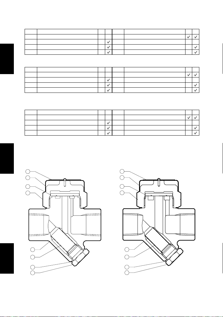
2. Configuration Aufbau Configuration
Description
Description
M*
-
-
-
R*
-
M*
-
-
-
-
R*
-
No.
1
2
3
4
Body
Cover
Disc
Screen
No.
5
6
7
8
Screen Holder Gasket
Screen Holder
Cap
Nameplate
* M = Maintenance Kit; R = Repair Kit; replacement parts are available only in their respective kits.
W*
-
-
-
R*
-
W*
-
-
-
-
R*
-
Bauteil
Bauteil
Nr.
1
2
3
4
Gehäuse
Verschlusskappe
Ventilteller
Schmutzsieb
Nr.
5
6
7
8
Siebstopfendichtung
Siebhaltestopfen
Isolierkappe
Typenschild
* W = Wartungs satz; R = Reparatursatz; Ersatzteile werden nicht einzeln, sondern als Teil dieser
beiden Einheiten geliefert.
E*
-
-
-
R*
-
E*
-
-
-
-
R*
-
Désignation Désignation
No.
1
2
3
4
Corps
Couvercle
Disque
Crépine
No.
5
6
7
8
Joint porte-crépine
Porte-crépine
Chapeau isolant
Plaquette nominative
*E = Jeu de pièces d'entretien; R = Jeu de pièces de réparation; les pièces de remplacement ne
sont disponibles que sous la forme de jeux de pièces.
8
4
2
3
1
5
6
7
P46S P21S ver.C
8
4
2
3
1
5
6
7
English
Deutsch
―5―
Français
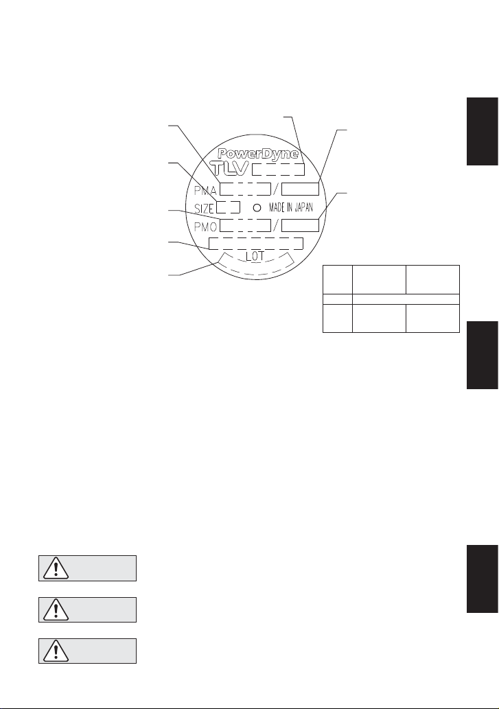
3. Specifications Technische Daten Données techniques
Refer to the product nameplate for detailed specifications.
Die technischen Daten stehen auf dem Typenschild.
Les données techniques sont inscrites sur la plaquette nominative.
Maximum Allowable Pressure*
Maximal zuässiger Druck*
Pression maximale admissible*
Nominal Diameter
Größe (DN)
Dimension (DN)
Maximum Operating Pressure**
Maximaler Betriebsdruck**
Pression de fonctionnement
maximale**
Maximum Allowable Back Pressure: 80% of inlet pressure
Maximal zulässiger Gegendruck: 80% des Vordrucks
Contre-pression maximale: 80% de la pression amont
* Maximum allowable pressure (PMA) and maximum allowable temperature (TMA) are
PRESSURE SHELL DESIGN CONDITIONS, NOT OPERATING CONDITIONS.
** P46S : For best performance over extended periods, it is recommended that the trap be
operated at or below 2.1 MPaG (300 psig).
*** Valve No. is displayed for products with options. This item is omitted from the nameplate when
there are no options.
* Maximal zulässiger Druck (PMA) und maximal zulässige Temperatur (TMA) sind
AUSLEGUNGSDATEN NICHT BETRIEBSDATEN.
** P46S : Um dauerhaft stabilen Betrieb zu garantieren, empfiehlt es sich, den Kondensatableiter
für Drücke bis 21 bar ü zu verwenden.
*** Die Valve No. wird angegeben bei Typen mit Optionen. Bei Typen ohne Optionen bleibt diese
Stelle frei.
* Pression maximale admissible (PMA) et température maximale admissible (TMA) sont les
CONDITIONS DE CONCEPTION, PAS LES CONDITIONS DE FONCTIONNEMENT.
** P46S : Pour assurer une meilleure performance à long terme, il est conseillé d'utiliser le
purgeur à une pression inférieure ou égale à 21 bar.
*** Le Valve No. est indiqué sur les modèles avec options. Ce numéro ne figure pas sur les
modèles sans options.
Valve No.***
Production Lot No.
Fertigungslos-Nr.
Lot de Production N°
Model
Typ
Modèle
Max. Allowable
Temperature* TMA
Max. zulässige
Temperatur* TMA
Température maximale
admissible* TMA
Max. Operating
Temperature TMO
Max. Betriebstemp. TMO
Temp. de fonctionnement maximale TMO
Minimum Operating Pressure
Minimaler Betriebsdruck
Pression de fonctionnement minimale
Horizontal
Waagerecht
Horizontal
0.03 MPaG (5 psig, 0.3 barg)
P46S
0.025 MPaG
P21S
(3.5 psig)
ver.C
(0.25 barg)
Vertical
Senkrecht
Vertical
0.04 MPaG
(6 psig)
(0.4 barg)
English
Deutsch
CAUTION
VORSICHT
ATTENTION
To avoid malfunctions, product damage, accidents or serious injury,
install properly and DO NOT use this product outside the specification
range. Local regulations may restrict the use of this product to below the
conditions quoted.
Die Einbauhinweise beachten und die spezifizierten Betriebsgrenzen
NICHT ÜBERSCHREITEN. Nichtbeachtung kann zu Betriebsstörungen
oder Unfällen führen. Lokale Vorschriften, können zur Unterschreitung der
angegebenen Werte zwingen.
Installer le produit correctement et NE PAS l’utiliser en dehors des plages
spécifiées. En cas de dépassement des limites données, des dysfonctionnements ou accidents pourraient survenir. Il se peut que des règlements
locaux limitent l'utilisation du produit en-deçà des spécifications indiquées.
6
Français
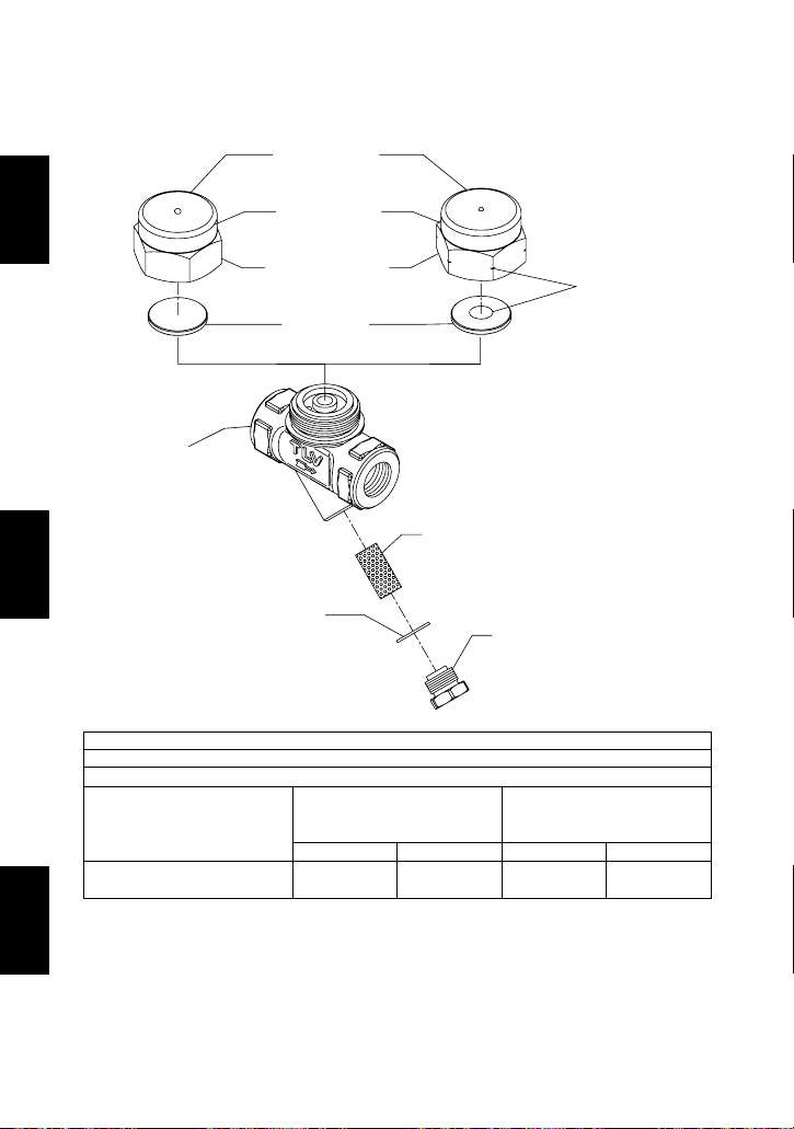
4.
Exploded View Einzelteile Pièces détachées
Tightening Torque and Distance Across Flats
Anzugsmomente und Schlüsselweiten
Moments de torsion et ouvertures de clé
N
•
m
120
P46S
P21S ver. C
(lbf
•
ft)
(88)mm36
(in)
(1 )
N•m40(lbf•ft)
(29)mm17
(in)
( )
Cover
Verschlusskappe
Couvercle
Screen Holder
Siebhaltestopfen
Porte-crépine
Model
Typ
Modèle
1 N·m
〜
〜
10 kg·cm
32
21
/
32
13
/
If drawings or other special documentation were supplied for the product, any torque given there
takes precedence over values shown here.
Falls Zeichnungen oder andere spezielle Dokumente mit dem Produkt geliefert wurden, haben Angaben
über Anzugsmomente in diesen Unterlagen Vorrang über den hier gezeigten Anzugsmomenten.
Si des dessins ou autres documents spéciaux ont été fournis pour le produit, les moments de
torsion donnés dans ces documents doivent être pris en compte plutôt que les valeurs données ici.
Cover
Verschlusskappe
Couvercle
Nameplate
Typenschild
Plaquette nominative
Cap
Isolierkappe
Chapeau isolant
Disc
Ventilteller
Disque
Body
Gehäuse
Corps
Screen Holder Gasket
Dichtung Siebhaltestopfen
Joint porte-crépine
Screen
Schmutzsieb
Crépine
Screen Holder
Siebhaltestopfen
Porte-crépine
Marking for P21S ver.C
Markierung P21S ver.C
Marques du P21S ver.C
English
Deutsch
―7―
Français
1.
The trap can be installed either horizontally or vertically, but make sure the arrow on the trap
points in the direction of flow.
2.
Before installation, be sure to remove all protective seals.
3.
Before installing the trap, blow out the inlet piping to remove all dirt and oil.
4.
Install the trap in the lowest part of the pipeline or equipment so the condensate flows naturally
into the trap by gravity.The inlet pipe should be as short and have as few bends as possible.
5.
Support the pipes properly within 800 mm (2.5 ft) on either side of the trap.
6.
Install a bypass valve to discharge condensate, and inlet and outlet valves to isolate the trap in
the event of trap failure or maintenance.
7.
Install a check valve at the trap outlet whenever more than one trap is connected to the
condensate collection pipeline.
8. In order to avoid excessive back pressure, make sure the discharge pipes are large enough;
(
the outlet back pressure allowance should be no more than 80% of the inlet steam pressure
).
9.
We recommend unions to facilitate connection and disconnection of the trap.
5. Proper Installation
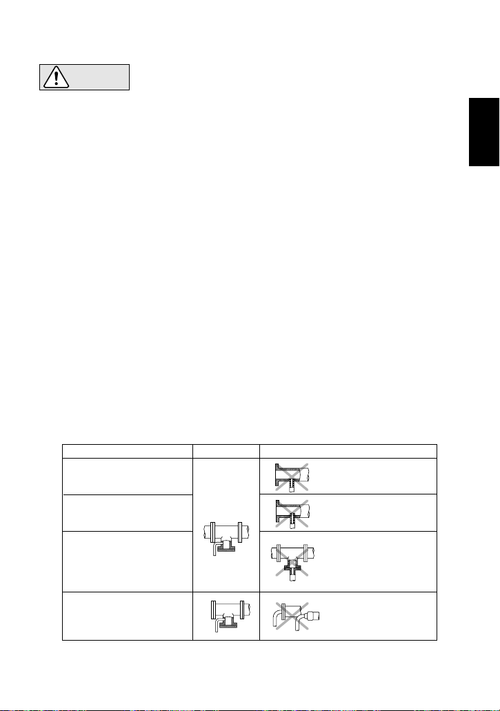
6. Piping Arrangement
Requirement
Diameter is too small.
Diameter is too small
and inlet protrudes
into pipe.
Rust and scale flow
into the trap with the
condensate.
Condensate collects
in the pipe.
Correct
Incorrect
Install a catchpot of the
proper diameter.
Make sure the flow of
condensate is not
obstructed.
To prevent rust and scale
from flowing into the trap,
connect the inlet pipe 25 50 mm (1 - 2 in) above the
base of the T - pipe.
When installing on the blind
end, make sure nothing
obstructs the flow of
condensate.
• Installation, inspection, maintenance, repairs, disassembly, adjustment
and valve opening/closing should be carried out only by trained
maintenance personnel.
• Take measures to prevent people from coming into direct contact with product outlets.
• Install for use under conditions in which no freeze-up will occur.
• Install for use under conditions in which no water hammer will occur.
CAUTION
Check to make sure that the pipes connected to the trap have been installed properly.
1. Is the pipe diameter suitable, and has sufficient space been secured for maintenance?
2. Has the trap been installed with the arrow on the body pointing in the direction of flow?
3. Have maintenance valves been installed at the inlet and outlet? If the outlet is subject to
back pressure, has a check valve been installed?
4. Is the inlet pipe as short as possible, with as few bends as possible, and installed so that the
condensate will flow naturally down into the trap?
5. Has the piping work been done correctly, as shown in the table below?
English
―8―
 Loading...