

TLV PN-COSR-16 Instruction Manual
172-65604MA-00 (PN-COSR-16 Pneumatic Control Valve) 10 September 2014
ISO 9001/ ISO 14001
Manufacturer
Kakogawa, Japan
is approved by LRQA LTD. to ISO 9001/14001
Pneumatic Control Valve for Steam
PN-COSR-16
Copyright © 2014 by TLV CO., LTD.
All rights reserved

Contents
1
Introduction ........................................................................ 1
Safety Considerations........................................................ 2
Specifications..................................................................... 4
Acceptable Operating Range............................................. 4
Correct Usage of the PN-COSR-16 ................................... 5
Configuration...................................................................... 7
Installation.......................................................................... 9
Operation ......................................................................... 14
Maintenance..................................................................... 17
Disassembly..................................................................... 18
Reassembly ..................................................................... 22
Troubleshooting ............................................................... 23
Product Warranty............................................................. 25
Introduction
Thank you for purchasing the pneumatic control valve for steam, model
COSR-16
This product has been thoroughly inspected before being shipped from the factory.
When the product is delivered, before doing anything else, check the specifications
and external appearance to make sure nothing is out of the ordinary. Also be sure to
read this manual carefully before use and follow the instructions to be sure of using
the product properly.
The PN-COSR-16 can operate automatically and provide accurate pressure control and
temperature control when combined with the
a general-purpose controller. Manual remote setting is possible by combination with an
air regulator.
If detailed instructions for special order specifications or options not contained in this
manual are required, please contact
This instruction manual is intended for use with the model(s) listed on the front cover.
It is needed not only for installation, but also for subsequent maintenance,
disassembly/reassembly and troubleshooting. Please keep it in a safe place for future
reference.
.
SC-F70 digital indicator controller or
for full details.
PN-
172-65604MA-00 (PN-COSR Pneumatic Control Valve) 10 Sep 2014
2
R
Safety Considerations
Read this section carefully before use and be sure to follow the instructions.
Installation, inspection, maintenance, repairs, disassembly, adjustment and valve
opening/closing should be carried out only by trained maintenance personnel.
The precautions listed in this manual are designed to ensure safety and prevent
equipment damage and personal injury. For situations that may occur as a result
of erroneous handling, three different types of cautionary items are used to
indicate the degree of urgency and the scale of potential damage and danger:
DANGER, WARNING and CAUTION.
The three types of cautionary items above are very important for safety: be sure to
observe all of them as they relate to installation, use, maintenance and repair.
Furthermore, TLV accepts no responsibility for any accidents or damage occurring
as a result of failure to observe these precautions.
Symbols
Indicates a DANGER, WARNING or CAUTION item.
DANGE
WARNING
CAUTION
CAUTION
Indicates an urgent situation which poses a threat of death or
serious injury
Indicates that there is a potential threat of death or serious injury
Indicates that there is a possibility of injury or equipment / product
damage
Install properly and DO NOT use this product outside the
recommended operating pressure, temperature and other
specification ranges.
Improper use may result in such hazards as damage to the
product or malfunctions that may lead to serious accidents. Local
regulations may restrict the use of this product to below the
conditions quoted.
Use hoisting equipment for heavy objects (weighing
approximately 20 kg (44 lb) or more).
Failure to do so may result in back strain or other injury if the
object should fall.
Take measures to prevent people from coming into direct
contact with product outlets.
Failure to do so may result in burns or other injury from the
discharge of fluids.
When disassembling or removing the product, wait until the
internal pressure equals atmospheric pressure and the
surface of the product has cooled to room temperature.
Disassembling or removing the product when it is hot or under
pressure may lead to discharge of fluids, causing burns, other
injuries or damage.
Safety considerations continued on the next page
172-65604MA-00 (PN-COSR Pneumatic Control Valve) 10 Sep 2014

3
CAUTION
Be sure to use only the recommended components when
repairing the product, and NEVER attempt to modify the
product in any way.
Failure to observe these precautions may result in damage to the
product and burns or other injury due to malfunction or the
discharge of fluids.
Do not use excessive force when connecting threaded pipes
to the product.
Over-tightening may cause breakage leading to fluid discharge,
which may cause burns or other injury.
Use only under conditions in which no freeze-up will occur.
Freezing may damage the product, leading to fluid discharge,
which may cause burns or other injury.
Use only under conditions in which no water hammer will
occur.
The impact of water hammer may damage the product, leading to
fluid discharge, which may cause burns or other injury.
Make sure the power supply is OFF before carrying out
work on the wiring or inspections involving disassembly.
If such work is carried out with the power on, there is a danger
that equipment may malfunction or electric shock may occur,
leading to injury or other accidents.
Make sure that wiring work requiring a special license is
carried out by qualified personnel.
If carried out by unqualified personnel, overheating or short circuits
leading to injury, fires, damage or other accidents may occur.
When using this product, NEVER stand close to, or leave
tools anywhere near moving parts, such as the shaft.
Contact with moving parts or objects becoming caught in moving
parts could lead to injury or damage or other accidents.
172-65604MA-00 (PN-COSR Pneumatic Control Valve) 10 Sep 2014
Specifications
CAUTION
CAUTION
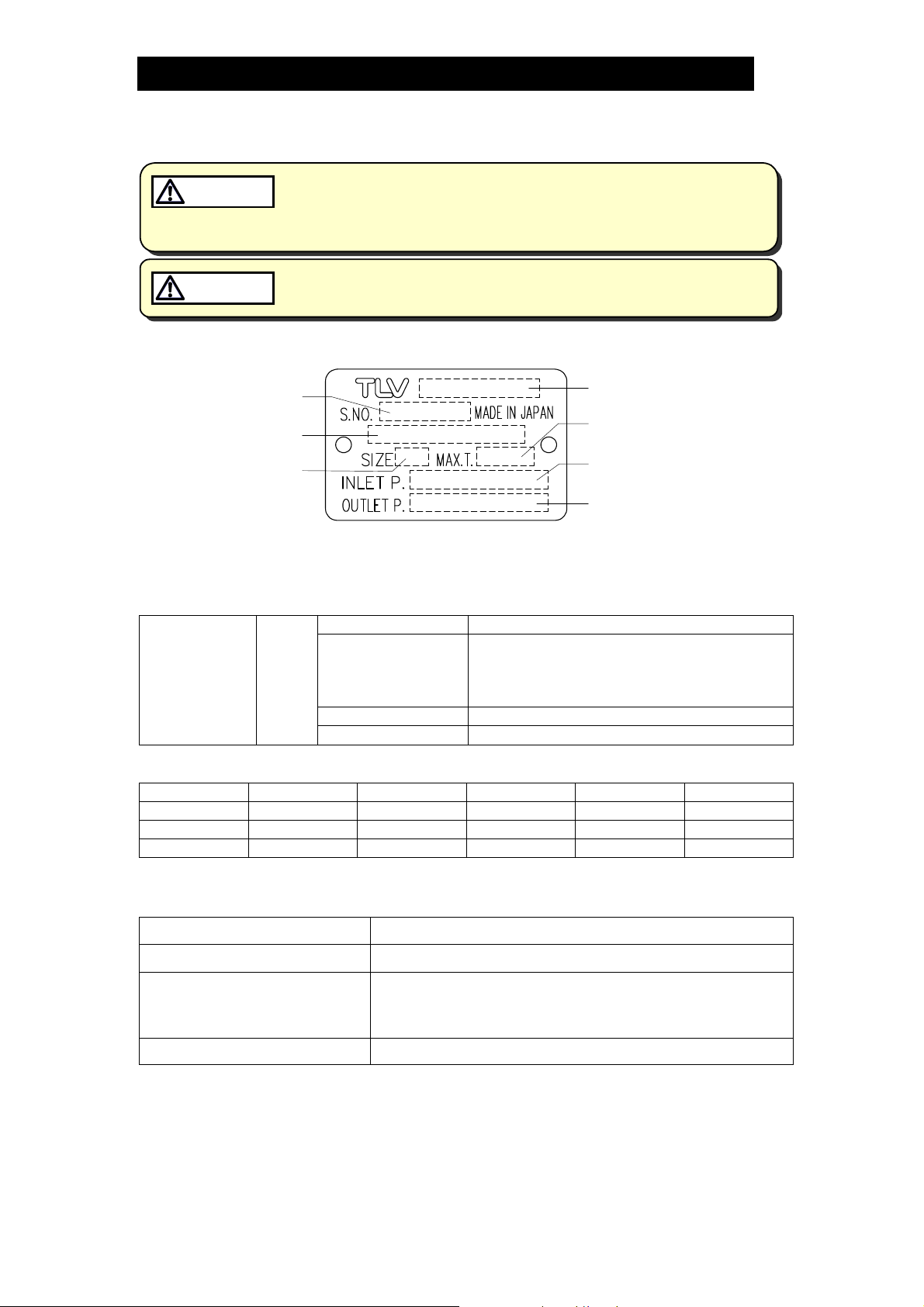
Refer to the product nameplate for detailed specifications.
Install properly and DO NOT use this product outside the recommended
operating pressure, tempera ture and other specification ranges.
Improper use may result in such hazards as damage to the product or
malfunctions which ma y lea d to serious accidents. Local regulations
may restrict the use of this product to below the conditions quoted.
Use only under conditions in which no freeze-up will occur. Freezing
may damage the product, leading to fluid discharge, which may cause
burns or other injury.
4
Serial Number
Valve No.*
Nominal Diameter
Model
Maximum Operating
Temperature
Primary Pressure Range
Secondary Pressure
Adjustable Range
* Valve No. is displayed for products with options. This item is omitted from the nameplate
when there are no options.
<Required Utilities>
Adjustment
Section
(Drive Section)
Motive
Air
Maximum Pressure 1.6 MPaG (250 psig)
Required Air
Pressure
[Desired secondary pressure + 0.1] MPaG
or higher
[Desired secondary pressure + 15] psig
or higher
Air Connecting Port Rc(PT), BSP or NPT 1/4 in
Air Quality
Oil-free air, filtered to 5 m
(1 MPa = 10.197 kg/cm2)
<CV Value>
Size: mm (in) 15 (1/2) 20 (3/4) 25 (1) 40 (11/2) 50 (2)
CV (U S ) 3.8 6.9 11.1 24.0 37.2
CV (U K ) 3.2 5.7 9.2 20.0 31.0
Kvs ( D I N) 3.3 5.9 9.5 20.6 31.9
Acceptable Operating Range
Model PN-COSR-16
Primary Pressure Range* 0.2 –1.6 MPaG (30 – 250 psig)
Adjustable Pressure Range
(All conditions must be met)
Pressure differntial between 0.07
Minimum Adjustable Flow Rate 5% of rated flow rate
*For process temperature control, the desired process temperature must be controllable by a
secondary pressure within the adjustable pressure range of the PN-COSR-16.
172-65604MA-00 (PN-COSR Pneumatic Control Valve) 10 Sep 2014
Within 10 – 84% of the primary pressure
(Minimum adjustable pressure of 0.03 MPaG (5 psig)
0.85 MPa (10 – 120 psi)
–
(1 MPa = 10.197 kg/cm2)
Correct Usage of the PN-COSR-16
5
CAUTION
Install properly and DO NOT use this product outside the recommended
operating pressure, temperature and other specification ranges.
Improper use may result in such hazards as damage to the product or
malfunctions which may lea d to serious accidents. Local regulations
may restrict the use of this product to below the conditions quoted.
1. The PN-COSR-16 should be operated only within its specifications.
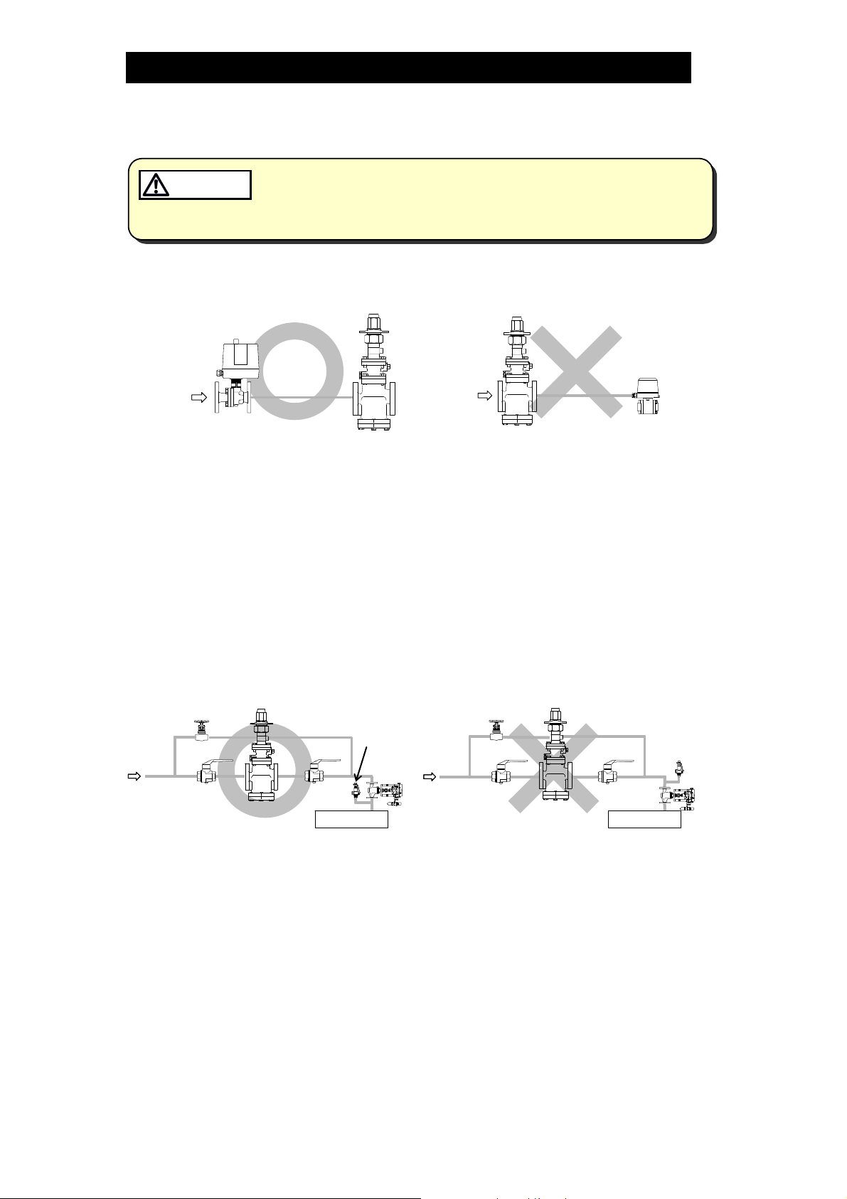
2. Installing an ON/OFF Valve (Solenoid Valve or Motorized Valve)
Motorized
Motorized
Valve
Valve
PN-COSR
PN-COSR
Inlet side
Inlet side
PN-COSR
PN-COSR
Outlet side
Outlet side
Solenoid
Solenoid
Valve
Valve
If an on-off valve, such as a motorized valve, is required to stop supply of steam
to the steam-using equipment, install it at the inlet side of the PN-COSR-16. If a
solenoid valve is installed at the outlet of the PN-COSR-16, its opening and
closing will cause heavy chattering and may lead to damage of the piston and
main valve. (When the on-off valve opens, the secondary pressure of the PN-
COSR-16 changes from zero to the set pressure. Passing through an area of
the reducing ratio of less than 10:1, where adjustment is impossible, chattering
occurs momentarily.) To save energy, it is recommended to install the on-off
valve as near to the boiler as possible.
NOTE: To prevent water hammer, it is recommended that a slow-acting motorized
on-off valve be used. In particular, if a fast-acting on-off solenoid valve is
used for frequent temperature control, the potential water hammer effect
can damage the steam-using equipment and the PN-COSR-16.
3. Installing a Control Valve
PN-COSR
Equipment
Safety
Valve
Control
Valve
PN-COSR
Safety
Valve
Equipment
A control valve installed between the PN-COSR-16 and the steam-using
equipment (downstream of the PN-COSR-16) for controlling equipment
temperature may raise the pressure between the PN-COSR-16 and the control
valve when the control valve is closed, depending on the spatial relationship. A
safety valve should be installed downstream of the control valve.
NOTE: When installing a safety valve to protect the steam-using equipment, be sure
to install it on the steam-using equipment or directly before the inlet of the
steam-using equipment. If the safety valve is installed on the outlet side of
the PN-COSR-16 between the PN-COSR-16 and a control valve, an
eventual pressure rise could activate the safety valve.
Control
Valve
172-65604MA-00 (PN-COSR Pneumatic Control Valve) 10 Sep 2014
6
r
f
f
e
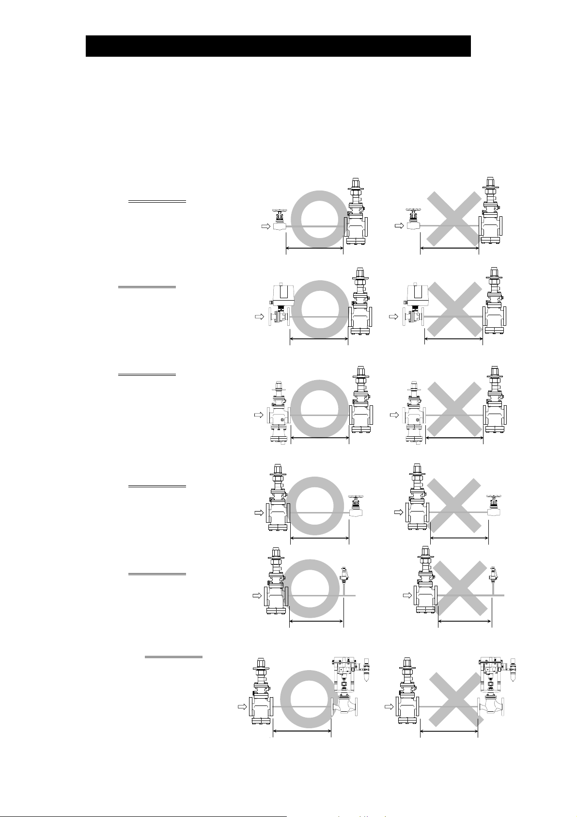
4 Precautions for the Installation of Additional Fittings Before or After the PN-COSR-16
In order to ensure stable steam flow, the piping upstream and downstream of the PN-
COSR-16 must be straight runs. If the PN-COSR-16 is installed either directly before o
after an elbow or control valve, unevenness in steam flow may result in chattering and
unstable pressure. To ensure stable steam flow, it is recommended that the PN-COSR-
16 be installed on straight runs of piping, as illustrated below.
1) Inlet (primary side) of the PN-COSR-16
Maintain a straight piping run
of 10 d or more
when a
manual valve, a strainer or an
Valve,
strainer,
elbow, etc.
PN-COSR
(d = pipe diameter)
Valve,
strainer,
elbow, etc.
PN-COSR
elbow, etc. is installed.
(Example: if nominal size is 25
mm (1 in), have 250 mm (10
in) or more)
Maintain a straight piping run o
30 d or more when an
10 d or more
Motorized
Valve
PN-COSR
Motorized
Valve
Less than
10 d
PN-COSR
motorized valve (on-off valve)
is installed.
(Example: if nominal size is 25
mm (1 in), have 750 mm (30
in) or more)
Maintain a straight piping run o
30 d or more when a pressur
Pressure
Reducing
reducing valve is installed.
Valve
30 d or more
PN-COSR
Pressure
Reducing
Valve
Less than
30 d
PN-COSR
(Two-stage pressure
reduction)
(Example: if nominal size is
25 mm (1 in), have 750 mm
(30 in) or more)
2) Outlet (secondary side) of the PN-COSR-16
Maintain a straight piping run
of 15 d or more
when a
manual valve, a strainer or an
30 d or more
PN-COSR Valve,
strainer,
elbow, etc.
Less than
30 d
PN-COSR
Valve,
strainer,
elbow, etc.
elbow, etc. is installed.
(Example: if nominal size is 25
mm (1 in), have 375 mm (15
in) or more)
Maintain a straight piping run
of 30 d or more
when a
15 d or more
PN-COSR
Safety
Valve
Less than
15 d
PN-COSR
Safety
Valve
safety valve is installed.
(Example: if nominal size is 25
mm (1 in), have 750 mm (30
in) or more)
Maintain a straight piping
run of 30 d or more
when a
control valve or an
30 d or more
PN-COSR
Control or
Automated
Valve
Less than
30 d
Control or
Automated
Valve
PN-COSR
automated valve (on-off
valve) is installed.
(Example: if nominal size is
25 mm (1 in), have 750
mm (30 in) or more)
30 d or more
Less than
30 d
172-65604MA-00 (PN-COSR Pneumatic Control Valve) 10 Sep 2014
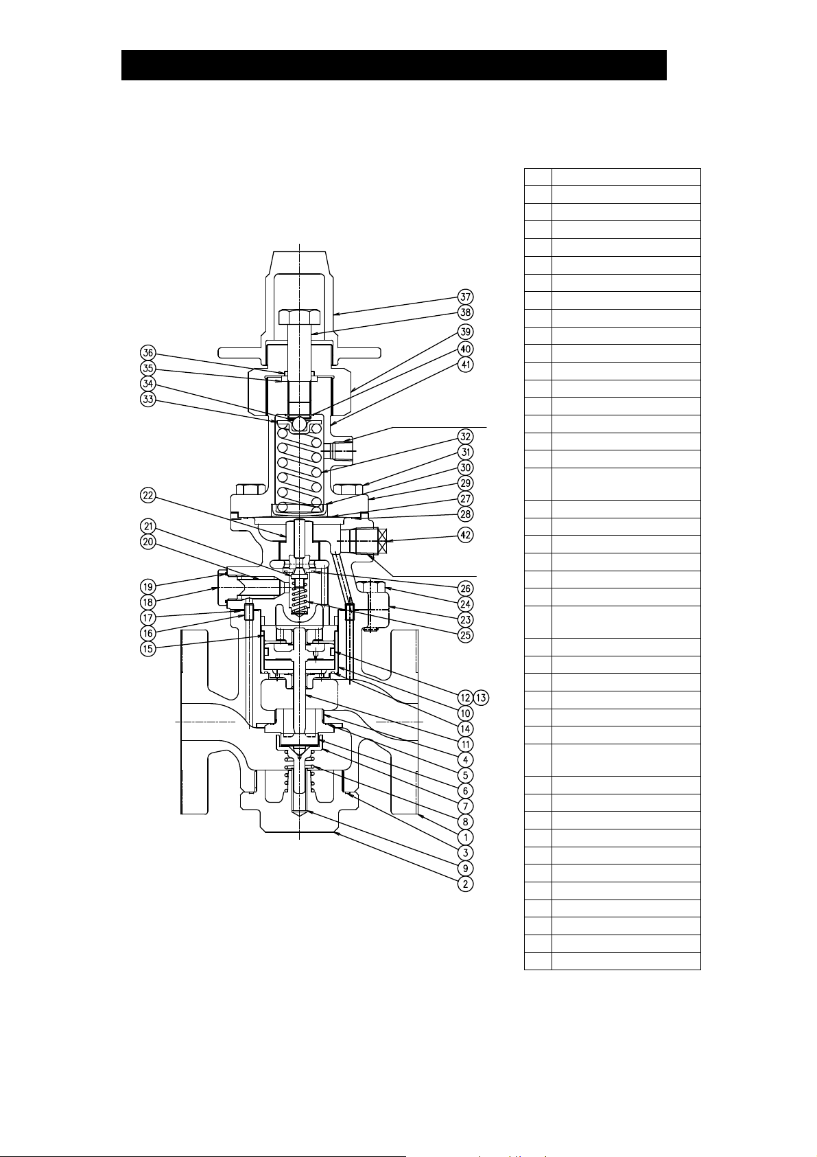
Configuration
15 – 25 mm (1/2 – 1 in)
8 mm (1/4in)
Motive Air Port
10 mm (3/8in)
*North American model does not equip this plug.
7
No. Name
Main Body
1
Cover Plug
2
Cover Plug Gasket
3
Main Valve Seat
4
Main Valve Seat Gasket
5
Main Valve
6
Main Valve Holder
7
Main Valve Spring
8
Sleeve
9
Cylinder
10
Piston
11
Piston Ring
12
Tension Ring
13
Cylinder Gasket
14
Piston Guide
15
Connecting Tube
16
Gasket (Pilot Body/
17
Main Body)
Pilot Screen Holder
18
Pilot Screen Holder Gasket
*
19
Pilot Screen
20
Pilot Valve
21
Pilot Valve Seat
22
Pilot Body
23
Hex Bolt (Pilot
24
Body/Main Body)
Pilot Valve Spring
25
Pilot Valve Seat Gasket
26
Diaphragm
27
Diaphragm Gasket
28
Spring Housing
29
Diaphragm Support
30
Hex Bolt (Spring
31
Housing/Pilot Body)
Coil Spring
32
Spring Retainer
33
Steel Ball
34
Gland Packing
35
O-ring
36
Spanner Cap
37
Adjustment Screw
38
Packing Retainer
39
C-ring
40
Nameplate
41
Plug – Sensing line Port*
42
172-65604MA-00 (PN-COSR Pneumatic Control Valve) 10 Sep 2014
 Loading...