

Deutsch
English
INSTRUCTION MANUAL
TEMPERATURE CONTROL STEAM TRAP
EINBAU- UND BETRIEBSANLEITUNG
TEMPERATUREINSTELLBARER KONDENSATABLEITER
LEX3N-TZ
LEX3N-TZ
LEX3N-TZ
LEX3N-TZ
Copyright (C) 2014 by TLV CO., LTD. All rights reserved.
Keep this manual in a safe place for future reference
Gebrauchsanleitung leicht zugänglich aufbewahren
INSTRUKCJA OBSŁUGI
Przechowuj instrukcję z bezpiecznym miejscu
ODWADNIACZ BIMETALICZNY Z NASTAWĄ TEMPERATURY
POLSKI

Introduction
Before beginning installation or maintenance, please read this manual to ensure correct use of
the product. Keep the manual in a safe place for future reference.
The inline repairable LEX3N-TZ temperature control steam trap with built-in scale removal
function is suitable for the accurate control of condensate discharge temperatures for
applications with operating pressures up to 4.6 MPaG (650 psig).
DO NOT USE on any application except steam tracing lines, storage tank coils, instrument
enclosures, steam trap air venting, and freeze protection of condensate line.
Note: The LEX3N-TZ can only control the temperature of condensate discharge from the trap; it
cannot control product temperature nor the temperature of condensate backing up in the system.
1 MPa = 10.197 kg/cm
2
, 1 bar = 0.1 MPa
For products with special specifications or with options not included in this manual, contact TLV
for instructions.
The contents of this manual are subject to change without notice.
Einführung
Bitte lesen Sie die Betriebsanleitung vor Einbau und Inbetriebnahme sorgfältig durch und
bewahren Sie sie für späteren Gebrauch an einem leicht zugänglichen Ort auf.
Der in der Leitung wartbare Kondensatableiter LEX3N-TZ mit eingebauter Funktion zur
Entfernung von Ablagerungen und mit genau einstellbarer Kondensatablasstemperatur kann für
Anlagen mit Betriebsdrücken bis zu 46 bar ü eingesetzt werden.
NICHT BENUTZEN für beliebige Anwendungen außer für Begleitheizung, Behälterbeheizung,
Schaltschrankbeheizung, Entlüftung von Kondensatableitern, und als Frostschutzventil in
Kondensatleitungen.
Hinweis: LEX3N-TZ Kondensatableiter regeln nur die Kondensatablasstemperatur, nicht aber die
Produkttemperatur oder die Temperatur von im System rückgestautem Kondensat.
1 bar = 0,1 MPa
Wenden Sie sich an TLV für Sonderausführungen, die nicht in dieser Einbau- und
Betriebsanleitung enthalten sind.
Wir behalten uns vor, den Inhalt dieser Betriebsanleitung ohne Ankündigung zu ändern.
Deutsch
English
Wstęp
Przed montażem należy zapoznać się z niniejszą instrukcją. Należy ją przechowywać w
bezpiecznym miejscu dla wykorzystania w razie potrzeby
Odwadniacze serii LEX3N-TZ są naprawialne bez demontażu z rurociągu w funkcją
nastawy temperatury oraz usuwania osadów na gnieździe. Umożliwia odprowadzanie
kondensatu w instalacjech do ciśnienia 4.6 MPa g (650 psig).
eznaczony do odwadniania parogrzejek, małych wężownic , ogrzewania miesjcowego ,
Prz
zabezpiecenia przed zamarzaniem nie stosować do innych zastosowań.
Uwaga : Odwadniacz LEX-TX nie może służyć do regulacji temperatury ogrzewnago produktu
Polski
1 bar = 0,1 MPa
Dla specjalnych zastosowań prosimy o kontakt z firmą TLV
Treść niniejszej instrukcji może się zmieniać bez powiadomienia
―1―
1. Safety Considerations
―2―
English
• Read this section carefully before use and be sure to follow the instructions.
• Installation, inspection, maintenance, repairs, disassembly, adjustment and valve
opening/closing should be carried out only by trained maintenance personnel.
• The precautions listed in this manual are designed to ensure safety and prevent equipment
damage and personal injury. For situations that may occur as a result of erroneous handling,
three different types of cautionary items are used to indicate the degree of urgency and the
scale of potential damage and danger: DANGER, WARNING and CAUTION.
• The three types of cautionary items above are very important for safety; be sure to observe
all of them, as they relate to installation, use, maintenance, and repair. Furthermore, TLV
accepts no responsibility for any accidents or damage occurring as a result of failure to
observe these precautions.
Indicates an urgent situation that poses a threat of death or serious injury.
Indicates a DANGER, WARNING or CAUTION item.
Indicates that there is a potential threat of death or serious injury.
CAUTION
WARNING
DANGER
CAUTION
Indicates that there is a possibility of injury, or equipment/product
damage.
Install properly and DO NOT use this product outside the
recommended operating pressure, temperature and other specification
ranges. Improper use may result in such hazards as damage to the product
or malfunctions, which may lead to serious accidents. Local regulations
may restrict the use of this product to below the conditions quoted.
Take measures to prevent people from coming into direct contact
with product outlets. Failure to do so may result in burns or other injury
from the discharge of fluids.
Always wear heat-insulated gloves when handling products with high
body temperatures, such as when in operation. Failure to do so may
result in burns
.
Do not use excessive force when connecting threaded pipes to the
product. Over-tightening may cause breakage leading to fluid discharge,
which may cause burns or other injury.
When disassembling or removing the product, wait until the internal
pressure equals atmospheric pressure and the surface of the
product has cooled to room temperature. Disassembling or removing
the product when it is hot or under pressure may lead to discharge of
fluids, causing burns, other injuries or damage.
Be sure to use only the recommended components when repairing
the product, and NEVER attempt to modify the product in any way.
Failure to observe these precautions may result in damage to the product
or burns or other injury due to malfunction or the discharge of fluids.
Use under conditions in which no water hammer will occur. The
impact of water hammer may damage the product, leading to fluid
discharge, which may cause burns or other injury.
―3―
Deutsch
1. Sicherheitshinweise
•Bitte lesen Sie dieses Kapitel vor Beginn der Arbeiten sorgfältig durchund befolgen Sie die
Vorschriften.
•Einbau und Ausbau, Inspektion, Wartungs- und Reparaturarbeiten, Öffnen/Schließen von
Armaturen, Einstellung von Komponenten, dürfen nur von geschultem Wartungspersonal
vorgenommen werden.
•Die Sicherheitshinweise in dieser Einbau- und Betriebsanleitung dienen dazu, Unfälle,
Verletzungen, Betriebsstörungen und Beschädigungen der Anlagen zu vermeiden. Für
Gefahrensituationen, die durch falsches Handeln entstehen können, werden drei verschiedene
Warnzeichen benutzt: GEFAHR; WARNUNG; VORSICHT.
•Diese drei Warnzeichen sind wichtig für Ihre Sicherheit. Sie müssen unbedingt beachtet
werden, um den sicheren Gebrauch des Produktes zu gewährleisten und Einbau, Wartung und
Reparatur ohne Unfälle oder Schäden durchführen zu können. TLV haftet nicht für Unfälle oder
Schäden, die durch Nichtbeachtung dieser Sicherheitshinweise entstehen.
Dieses Zeichen weist auf GEFAHR, WARNUNG, VORSICHT hin.
VORSICHT
Die Einbauhinweise beachten und die spezifizierten Betriebsgrenzen
NICHT ÜBERSCHREITEN. Nichtbeachtung kann zu Betriebsstörungen
oder Unfällen führen. Lokale Vorschriften können zur Unterschreitung der
angegebenen Werte zwingen.
In sicherer Entfernung von Auslassöffnungen aufhalten und andere
Personen warnen, sich fernzuhalten. Nichtbeachtung kann zu
Verletzungen durch austretende Fluide führen.
Beim Umgang mit hohen Gehäusetemperaturen, wie sie während
des Betriebs auftreten, unbedingt hitzebeständige Handschuhe
benutzen. Nichtbeachtung kann zu Verbrennungen führen.
Vor Öffnen des Gehäuses und Ausbau von Teilen warten, bis der
Innendruck sich auf Atmosphärendruck gesenkt hat und das
Gehäuse auf Raumtemperatur abgekühlt ist. Nichtbeachtung kann zu
Verbrennungen oder Verletzungen durch austretende Fluide führen.
Zur Reparatur nur Original-Ersatzteile verwenden und NICHT
VERSUCHEN, das Produkt zu verändern. Nichtbeachtung kann zu
Beschädigungen führen, die Betriebsstörungen, Verbrennungen oder
andere Verletzungen durch austretende Fluide verursachen.
Bei Schraubanschlüssen keine übermäßige Kraft anwenden, damit
die Gewinde nicht beschädigt werden, was zu Verbrennungen oder
Verletzungen durch austretende Fluide führt.
Nur an Stellen einbauen, an denen kein Wasserschlag eintreten
kann. Wasserschlag kann das Produkt beschädigen und zu
Verbrennungen oder Verletzungen durch austretende Fluide führen.
bedeutet, dass eine unmittelbare Gefahr für Leib und Leben besteht.
bedeutet, dass die Möglichkeit der Gefahr für Leib und Leben besteht.
WARNUNG
GEFAHR
VORSICHT
bedeutet dass die Möglichkeit von Verletzungen oder Schäden an
Anlagen oder Produkten besteht.
1.
INSTRUKCJE BEZPIECZEŃSTWA
• Należy zapoznać się z tą instrukcją szczegółowo i stosować się do zawartych w niej zaleceń.
•
• Montaż, Inspekcja, Obsługa, Naprawa, Demontaż oraz inne prace związane z otwieraniem i
•
zamykaniem zaworów powinny być wykonywane tylko przez przeszkolony personel
•
Ostrzeżenia wymienione w niniejszym dokumencie zostały opracowane aby zapewnić
bezpieczeństwo, zapobiegać uszkodzeniom urządzeń oraz zranieniom osób obsługujących. Dla
sytuacji które mogą wystąpić w czasie błędnej obsługi, określono 3 główne typy zagrożeń i ich
oznaczenia w zależności od stopnia ryzyka wynikającego z uszkodzeń: ZAGROŻENIE,
OSTRZEŻENIE, UWAGA.
•
Trzy typy oznaczeń są bardzo ważne dla bezpieczeństwa i należy pamiętać aby zapoznać się z
nimi, gdyż dotyczą instalacji, stosowania, obsługi i naprawy. Firma TLV nie odpowiada za
jakiekolwiek wypadki i uszkodzenia wynikające z braku stosowania się do tych oznaczeń.
Sygnalizuje ZAGROŻENIE , OSTRZEŻENIE, UWAGA
ZAGROŻENIE
OSTRZEŻENIE
UWAGA
Sygnalizuje potencjalne zagrożenie śmiercią lub poważnym zranieniem
Sygnalizuje możliwość zranienia lub uszkodzenia urządzenia lub produktu
UWAGA
Sygnalizuje nagłą sytuację, która może grozić śmiercią lub
poważnym zranieniem
Należy prawidłowo instalować urządzenie. NIE WOLNO stosować urządzenia przy
parametrach spoza zakresu zalecanych ciśnień oraz temperatur pracy lub innych
ograniczeń podanych w specyfikacji urządzenia. Niewłaściwe zastosowanie może
prowadzić do uszkodzenia produktu, jego nieprawidłowej pracy,a nawet może
prowadzić do poważnych wypadków. Lokalne przepisy w tym względzie mogą być
bardziej restrykcyjne od podanych w specyfikacjach.
Należy podjąć kroki aby zapobiegać możliwości pojawienia się osób w
zasięgu wylotu urządzenia.
Niestosowanie się do powyższego może prowadzić do oparzeń lub zranień na
skutek kontaktu z czynnikiem wypływającym z urządzenia.
Podczas obsługi lub naprawy należy zawsze nosić odporne na temperatury
rękawice ochronne. Niestosowanie się może prowadzic do oparzeń.
Podczas demontażu oraz zdejmowania produktu z instalacji, należy poczekać
do momentu gdy ciśnienie wewnątrz urządzenia zrówna się z
ciśnieniem atmosferycznym i temperatura powierzchni urządzenia spadnie do
temperatury pokojowej.
Demontaż i zdejmowanie produktu z instalacji gdy jest gorące lub pod ciśnieniem
może prowadzić do wycieku czynnika powodując oparzenia lub uszkodzenia.
Należy upewnić się, że stosowane są tylko zalecane elementy do naprawy
urządzenia i NIGDY nie należy dokonywać modyfikacji urządzenia w jakikolwiek
sposób. Nie stosowanie się do powyższego może prowadzić do uszkodzeń produktu,
oparzeń lub innych zranień czy problemów z działaniem produktu oraz wydostania
się czynnika na zewnątrz.
Nie stosować nadmiernych sił podczas montażu urządzeń na połączeniach gwintowych.
Nadmierny moment może prowadzić do zerwania połączenia i wydostania się czynnika
na zewnątrz, co z kolei prowadzi do zagrożenia oparzeniem lub innym zranieniem.
Stosować w warunkach gdy nie występują uderzenia wodne. Uderzenia wodne
mogą doprowadzić do uszkodzenia urządzenia i w efekcie wydostania się czynnika
na zewnątrz co z kolei prowadzi do zagrożenia oparzeniem lub innym zranieniem.
Polski
―4―
2.
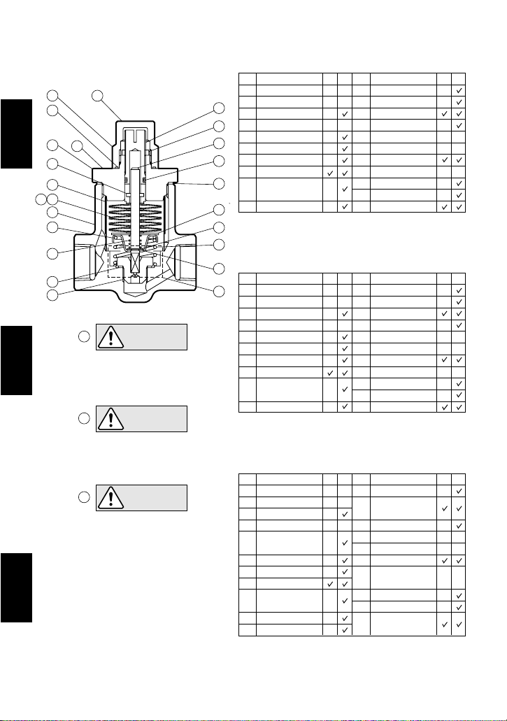
Configuration Aufbau Konfiguracja
LEX3N-TZ
16
21
2
English
B
12
14
56
1
19
10
8
7
A
Deutsch
A
NICHT ABNEHMEN, SOLANGE
DER KONDENSATABLEITER
A
Polski
A
CAUTION
DO NOT REMOVE
WHILE TRAP IS
UNDER PRESSURE
VORSICHT
UNTER DRUCK STEHT
UWAGA
NIE ZDEJMOWAĆ
POKRYWY GDY
ODWADNIACZ JEST
POD CIŚNIENIEM
Description
No.
1
Body
2
4
15
3
13
17
20
6
Cover
3
Valve Stem
4
Adjusting Screw
5
Bimetal Element
6
Washer
7
Valve Seat
8
Valve Seat Gasket
Overexpansion
9
Spring
10
Return Spring
Replacement parts are available only in the following kits:
M = Maintenance Kit; R = Repair Kit
MR M
No.
Description
11
Snap Ring
12
Spring Pin
13
Seal Ring
14
Screen
15
Locknut
16
Cap Nut
17
Cover Gasket
18
Nameplate
19
Spring Guide
20
Thrust Plate
21
Cap Nut Gasket
9
11
18
Bauteil
Nr.
1
Gehäuse
2
Gehäusedeckel
3
Ventilstange
4
Justierschraube
5
Bimetallpaket
6
Zwischenscheibe
7
Ventilsitz
8
Ventilsitzdichtung
Überdehn-
9
sicherung
10
Rückholfeder
Ersatzteile werden nur in ganzen Einheiten geliefert:
W = Wartungssatz; R = Reparatursatz
Opis
No.
Korpus
1
Pokrywa
2
Trzpień
3
Śruba nast.
4
Element
5
bimetaliczny
Podkładka
6
Gniazdo
7
Uszczelka
8
Sprężyna
9
zabezpiecz.
Sprężyna
10
Pierścień
11
Części zamienne sa dostępne w zestawach
naprawczych E = Inspekcyjnym ; R =
WR W
Nr.
11
Spannring
12
Spreizstift
13
Dichtring
14
ER
Schmutzsieb
15
Kontermutter
16
Kappe
17
Gehäusedichtung
18
Typenschild
19
Federführung
20
Stoßplatte
21
Kappendichtung
No.
Opis
Kołek
12
Uszczelnienie
13
Siatka filtra
14
Nakrętka
15
Pokrywa
16
Uszczelka
17
Tabliczka
18
znamionowa
Prowadnica
19
Płytka oporowa
20
Uszczelka
21
Naprawczym
Bauteil
R
R
E
R
―5―
―6―
3.
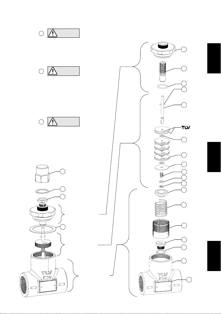
Exploded View Einzelteile Widok rozłożony
CAUTION
B
DO NOT REMOVE CAP NUT OR COVER WHILE
TRAP IS UNDER PRESSURE. Allow trap body
temperature to cool to room temperature before
removing cap nut or cover. Failure to do so may
result in burns or other injury. READ
INSTRUCTION MANUAL CAREFULLY.
VORSICHT
B
KAPPE ODER GEHÄUSEDECKEL NICHT
ABNEHMEN WÄHREND LEX UNTER DRUCK
STEHT. Vor Abnahme dieser Teile die
Gehäusetemperatur auf Raumtemperatur
abkühlen lassen. Nichtbeachtung kann zu
Verbrennungen oder Verletzungen durch
austretende Fluide führen. EINBAU- UND
BETRIEBSANLEITUNG SORGFÄLTIG
NIE ZDEJMOWAĆ POKRYWY (16) GDY
ODWADNIACZ JEST POD CIŚNIENIEM.
Poczekać aż odwadniacz ostygnie do
temperatury pokojowej i dopiero wtedy zdjąć
pokrywę (16). Niezastosowanie może
prowadzić do oparzenia lub innych ran czy
agrożeń. NALEŻY DOKŁADNIE ZAPOZNAĆ
z
DURCHLESEN.
UWAGA
B
SIĘ Z INSTRUCKJĄ
16
21
15
Cover Unit
Deckeleinheit
Pokrywa
17
2
4
13
12
3
6
5
20
10
6
11
19
9
14
English
Deutsch
Valve Unit
Ventileinheit
Moduł zaworu
Body Unit
Gehäuseeinheit
Korpus
7
8
1
Polski
18
4.
To avoid malfunctions, product damage, accidents or serious injury,
install properly and DO NOT use this product outside the specification
range. Local regulations may restrict the use of this product to below the
conditions quoted.
CAUTION
Die Einbauhinweise beachten und die spezifizierten Betriebsgrenzen
NICHT ÜBERSCHREITEN. Nichtbeachtung kann zu Betriebsstörungen
oder Unfällen führen. Lokale Vorschriften können zur Unterschreitung der
angegebenen Werte zwingen.
VORSICHT
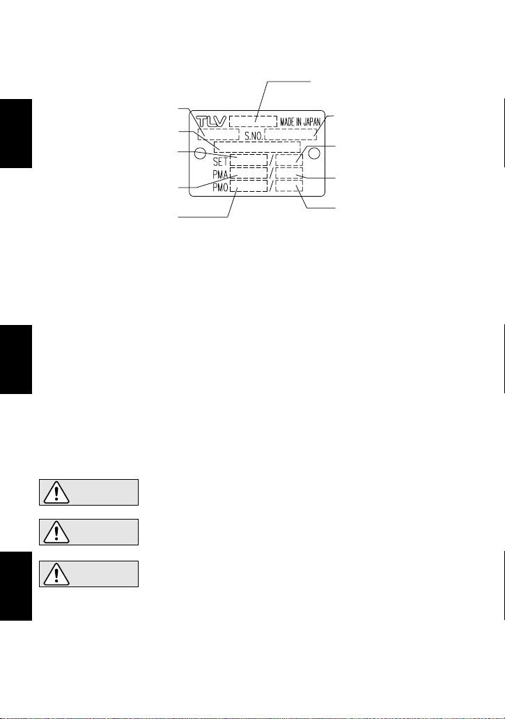
* Maximum allowable pressure (PMA) and maximum allowable temperature (TMA) are
PRESSURE SHELL DESIGN CONDITIONS, NOT OPERATING CONDITIONS.
**
Valve No. is displayed for products with options. This item is omitted from the nameplate
when there are no options
*** Set pressure and set temperature are the initial settings when shipped from the factory.
* Maximal zulässiger Druck (PMA) und maximal zulässige Temperatur (TMA) sind
AUSLEGUNGSDATEN, NICHT BETRIEBSDATEN.
**
Die Valve No. wird angegeben bei Typen mit Optionen. Bei Typen ohne Optionen bleibt diese
Stelle frei.
*** Einstelldruck und Einstelltemperatur zeigen die im Werk voreingestellten Werte.
*
Nominal Diameter
Größe/DN
Set Pressure***
Einstelldruck***
Valve No.**
Serial Number
Seriennummer
Model
Typ
―7―
Deutsch
English
Specifications Technische Daten Specyfikacja
Rozmiar/DN
Maximum Allowable Pressure*
Maksymalne dopuszczalne ciśnienie*
Maximum Operating Pressure
Maksymalne dopuszczalne cisnienie (PMA) oraz maksymalna dopuszczalna temperatura
(TMA) sa dopuszczalnymi parametrami korpusu a nie parametrami pracy
** Numer zaworu jest pokazany w przypadku opcji. Brak gdy nie ma opcji
***
CIśnienia nastawy i temperatura nastawy są parametrami nastawionymi w fabryce.
Nastawa ciśnienia***
Maximal zulässiger Druck*
Maximaler Betriebsdruck
Maksymalne cisnienie pracy
Typ
Numer seryjny
Set temperature***
Einstelltemperatur***
Nastawa temperatury***
Maximum Allowable Temperature* TMA
Maximal zulässige Temperatur* TMA
Maks. dopuszczalna temperatua* TMA
Maximum Operating Temperature TMO
Maximale Betriebstemperatur TMO
a temperatura robocza TMO
Maksymaln
Polski
UWAGA
NIE WOLNO stosować urządzenia przy parametrach spoza zakresu
zalecanych ciśnień oraz temperatur pracy lub innych ograniczeń
podanych w specyfikacji urządzenia. Niewłaściwe zastosowanie może
prowadzić do uszkodzenia produktu, jego nieprawidłowej pracy, a nawet
może prowadzić do poważnych wypadków. Lokalne przepisy w tym
względzie mogą być bardziej restrykcyjne od tych podanych w
specyfikacjach.
―8―
English
1.
Before installation, be sure to remove all protective seals.
2.
Before installing the product, blow out the inlet piping to remove any piping scraps, dirt and oil.
Close the inlet valve after blowdown.
3. Verify that piping is of a suitable diameter.
4. Install in a place where caution plates (including cap) can clearly be seen during periods of
maintenance, in the lowest part of the pipeline so that condensate flows into the trap by gravity.
5.
Install the product so that the arrow on the body is pointing in the direction of condensate flow.
6.
The trap may be installed either horizontally or vertically; there are no restrictions on the
orientation of installation. However, when installing horizontally, make sure that the trap is
installed with the temperature adjusting screw positioned higher than the piping in which the
trap is installed. (Upside-down installation is not permissible.)
7. When used as an automatic non-freeze valve, do not use thin-walled tubing for outlet piping.
As freezing occurs on outlet side, use a short, thick-walled pipe to discharge to atmosphere.
8. When used as an external air vent for TLV steam traps, connect to the top of the steam trap.
9. Install inlet and outlet valves to isolate the product in event of trap failure or maintenance.
6. Proper Installation
• Installation, inspection, maintenance, repairs, disassembly, adjustment
and valve opening/closing should be carried out only by trained
maintenance personnel.
CAUTION
7. Operational Check
A visual inspection can be carried out to aid in determining the necessity for immediate
maintenance or repair, if the trap is open to atmosphere. If the trap does not discharge to
atmosphere, use diagnostic equipment such as a stethoscope, thermometer or TLV TrapMan
(within its pressure and temperature measurement range).
Note: For socket weld connections, use electric arc welding with a single pass. As internal
parts are not damaged by one pass welding, there is no need to remove them before welding.
5. Applications
• DO NOT USE on any application except steam tracing lines, storage tank coils, instrument
enclosures, steam trap air venting, and freeze protection of condensate lines.
• SUITABLE for steam tracing lines or storage tank coils ONLY IF the required product
viscosity will be maintained when the condensate is sub-cooled at least 15 °C (27 °F), even to the
point of the condensate having a lower temperature than the product temperature.
• SUITABLE for use on instrument enclosures ONLY IF the steam or condensate temperature
in the enclosures will NOT damage the instrument.
• SUITABLE for use as an external air vent for TLV steam traps, or as a non-freeze valve for
freeze protection of condensate lines.
(When conducting a visual inspection, flash steam is sometimes mistaken for steam leakage. For
this reason, the use of a steam trap diagnostic instrument such as TLV TrapMan is highly
recommended.)
Normal:
Condensate is being discharged from the discharge outlet. (The surface temperature
of the trap should be about 10 to 20 °C (20 to 40 °F) lower than the set temperature.)
Blocked: No condensate is discharged and the surface temperature of the trap is low.
Blowing: Live steam continually flows from the outlet and there is a continuous hissing sound
of flow. The surface temperature of the trap is higher than the set temperature.
10.
If the product is subject to back pressure, install a check valve.
11.
Open the inlet valve gradually and check to make sure that the product functions properly.
• Take measures to prevent people from coming into direct contact with
product outlets.
• Install for use under conditions in which no water hammer will occur.

―9―
English
8. Adjusting Temperature Setting
Instructions for Adjusting Temperature Setting
1. First close the external valve from which the steam and condensate flow to the trap (the
“inlet isolation valve”), followed by then closing the external valve to which the condensate
flows from the trap (the “outlet isolation valve”). Wait until the pressure between the inlet
isolation valve and the trap equals atmospheric pressure (when the trap body temperature
cools to room temperature). Do not remove the cap nut unless the trap is isolated from and
is not subjected to steam pressure.
2. Hold the cover with one wrench and use another wrench to slowly loosen and remove the
cap nut. Remove cap nut slowly to allow any residual pressurized steam to leak from the
trap interior through the threads of the adjustment screw and the cover.
3. Hold the adjusting screw in place with a flat-head screwdriver and remove the locknut
slowly in case of any additional steam leakage.
4. Use a flat-head screwdriver to turn the adjusting screw to adjust temperature. To raise the
temperature setting, turn the adjusting screw counterclockwise. To lower the temperature
setting, turn the adjusting screw clockwise. Refer to the set temperature adjustment chart
for the number of turns required from the "0" position to reach the desired temperature.
5. After completing the adjustment, replace the locknut. Hold the adjusting screw in place with
a flat-head screwdriver and tighten the locknut securely.
6. Replace the cap nut and tighten it to the proper torque (see page 13).
7. First fully open the outlet isolation valve, followed by then slowly opening the inlet isolation
valve – carefully checking for any steam leaks that might occur. In the event steam leaks are
detected, immediately close the inlet isolation valve, then the outlet isolation valve, and
repair the source of leakage.
8. Check the temperature setting by observing an inline temperature sensor or by measuring
the temperature at the wrench flat on the trap’s inlet side at least 30 minutes after supplying
steam with the new setting. The trap set temperature will be approximately 10 to 20 °C (20
to 40 °F) higher than the surface reading. If the resultant temperature is not as desired,
repeat procedure from step 1 above.
• To prevent possible injury, always relieve pressure from trap before
opening to adjust the temperature setting.
•
Always wear heat-insulated gloves and eye protection when handling pro-
ducts exposed to high temperatures. Failure to do so may result in burns.
CAUTION
The temperature setting can be easily adjusted.
Adjusting
Screw
Adjuster Slot
Cover
A
B
Standard Factory Setting ("0" Position):
The standard "0" position is the position where point (A), the
bottom of the adjusting screw slot is even with point (B), the
top surface of the cap.
LEX3N-TZ
100 °C at 0.9 MPaG (9 barg),
212 °F at 130 psig
Temperature Setting Range
Set Temperature (˚F)
Operating pressure (psig)
Set Temperature (˚C)
Operating Pressure (MPaG)
50
100
150
200
0.1 0.4 0.80.50.30.2 1.5 4.631240.15
15 ˚C below saturated
steam temperature
15
120
200
300
400
20 30 50 100 300 500 650200
27 ˚F below saturated
steam temperature
1 MPa = 10.197 kg/cm2 = 10 bar

―10―
English
1. Start at the standard factory setting (point A) (100 °C at 0.9 MPaG, 9 barg; 212 °F at 130 psig).
2. Move up or down vertically to the desired set temperature (point B).
3. Follow the set temperature line in either direction to the vertical line corresponding to the
actual operating steam pressure (point C).
4. Follow the horizontal line to where it meets the left side of the chart (point D), indicating the
number and direction of turns required. (- turn: clockwise, + turn: counterclockwise)
Set Temperature Adjustment Chart
The trap can be set to open at any temperature between 50 °C and 200 °C (120 °F and 390 °F)
provided the set temperature is at least 15 °C (27 °F) below saturated steam temperature.
To determine the number and direction of adjusting screw turns required for the desired set
temperature, refer to the charts below.
-
turn: clockwise, + turn: counterclockwise
Standard "0" position = 100
˚
C at 0.9 MPaG, 9 barg; 212 ˚F at 130 psig
Operating Pressure (psig)
Number of Turns of Adjusting Screw
Operating Pressure (MPaG)
Number of Turns of Adjusting Screw
Set Temperature (˚C)
Set Temperature (˚F)
AA
BB
D
0.1 0.2 0.3 0.5 1 2 3 4.6
-21/2
+21/2
+31/2
+41/2
-11/2
+11/2
-1/2
+1/2
-2
-1
+1
0
+2
+3
+4
+5
200
190
180
170
160
150
140
130
120
110
90
100
80
70
60
50
CC
15 100 200 300 50065050
-21/2
+21/2
+31/2
+41/2
-11/2
+11/2
-1/2
+1/2
-2
-1
+1
AA
B
CC
D
0
+2
+3
+4
+5
390
380
360
340
300
320
280
260
240
220
210
200
180
160
140
120
1 MPa = 10.197 kg/cm2 = 10 bar
9. Cleaning Function
Rust, scale and other buildup on the valve seat may hinder the sealing ability of the steam trap
and cause steam leakage and resultant higher product temperature; or block the valve seat
opening - thereby preventing condensate discharge and resultant lowered product temperature.
The LEX3N-TZ contains a built-in cleaning device that can be used without removing the trap
from the line. Follow the steps below to remove contaminant accumulation from around the valve
opening.
• To prevent possible injury, always relieve pressure from trap before
opening to clean the trap.
• Always wear heat-insulated gloves and eye protection when handling pro ducts exposed to high temperatures. Failure to do so may result in burns.
CAUTION
Cleaning Function Instructions
1. First close the inlet isolation valve, followed by then closing the outlet isolation valve. Wait
until the pressure between the inlet isolation valve and the trap equals atmospheric pressure
(when the trap body temperature cools to room temperature). Do not remove the cap nut or
the cover unless the trap is isolated from and is not subjected to steam pressure.
2. Hold the cover with one wrench and use another wrench to slowly loosen and remove the
cap nut. Remove cap nut slowly to allow any residual pressurized steam to leak from the
trap interior through the threads of the adjustment screw and the cover. If steam leakage
occurs while loosening cap nut or locknut, disassemble the trap and replace both the
seal ring and the cover gasket (see chapter 10).
Continued on page 11

―11―
English
Operational inspections should be performed at least twice per year, or as called for by trap
operating conditions. Steam trap failure may result in temperature drop in the equipment, poor
product quality or losses due to steam leakage.
10. Inspection and Maintenance
• Installation, inspection, maintenance, repairs, disassembly, adjustment
and valve opening/closing should be carried out only by trained
maintenance personnel.
• Before attempting to open the trap, close the isolation valves and wait
until the trap has cooled completely. Failure to do so may result in
burns.
• Be sure to use the proper components and NEVER attempt to modify
the product.
CAUTION
3. Hold the adjusting screw in place with a flat-head screwdriver and remove the locknut slowly
in case of any additional steam leakage.
4. Check the current set position of the adjusting screw. Check and record the number of turns
required to return to the standard factory setting (when points (A) and (B) are even with each
other as shown on page 9).
5. Use a flat-head screwdriver to slowly turn the adjusting screw clockwise (to tighten) until it
stops. (This causes the cleaning edge of the stem to reach the valve seat and loosen debris).
6. Slowly turn the adjusting screw counterclockwise (to loosen) until it stops. (This will allow
flushing once the steam is safely turned on using the instructions that follow).
7. Replace the cap nut and tighten it to the proper torque (see page 13).
8. First fully open the outlet isolation valve, and then slowly and carefully open the inlet isolation
valve – checking for any steam leaks. In the event steam leaks are detected, immediately
close the inlet isolation valve, then the outlet isolation valve, and repair the source of leakage.
9. Wait 10 seconds to allow any loose scale to be flushed internally. Be aware of any external
steam leak – including the outlet connection if opened to atmosphere. Be careful to not come
in contact with any steam that is discharging from an open outlet connection. If any steam
leaks are detected elsewhere on the trap or piping, immediately close the inlet isolation valve,
then the outlet isolation valve, and repair the source of leakage.
10. Next, prepare to set the trap temperature again by first isolating the trap and safely relieving
all steam pressure from the trap as follows.
11. First close the inlet isolation valve, followed by then closing the outlet isolation valve. Wait
until the inlet pressure equals atmospheric pressure. (When the trap body temperature cools
to room temperature)
12. Hold the cover with one wrench and use another wrench to slowly remove the cap nut as in
step 2 above.
13. Slowly turn the adjusting screw clockwise (to tighten) to return to the original position
checked in step 4 above.
14. Replace the locknut. Hold the adjusting screw in place with a flat-head screwdriver and
tighten the locknut securely.
15. Replace the cap nut and tighten it to the proper torque (see page 13).
16. First fully open the outlet isolation valve, followed by then slowly opening the inlet isolation
valve – carefully checking for any steam leaks. In the event steam leaks are detected,
immediately close the inlet isolation valve, then the outlet isolation valve, and repair the
source of leakage.
17. Check the temperature setting by observing an inline temperature sensor or by measuring
the temperature at the wrench flat on the trap’s inlet side at least 30 minutes after supplying
steam with the new setting. The trap set temperature will be approximately 10 to 20 °C (20 to
40 °F) higher than the temperature reading on the trap body surface. If the resultant
temperature is not as desired, use the instructions for adjusting temperature settings (see
page 9).

―12―
Disassembly/Reassembly (to reassemble, follow procedures in reverse)
During Disassembly During Reassembly
Remove with a spanner or socket
wrench
Consult the table of tightening torques
and tighten to the proper torque
Remove and clean sealing
surfaces
Replace with a new gasket if warped or
damaged
Remove with a spanner or socket
wrench
Reattach and tighten
Remove with a spanner or socket
wrench
Line up spring pin in valve stem with
grooves cut into the adjusting screw as
cover is placed onto the body; consult
the table of tightening torques and
tighten to the proper torque
Remove and clean sealing
surfaces
Replace with a new gasket; coat
surfaces with anti-seize
Locknut 15
Cover 2
Cover Gasket 17
Screw in by using a flat-head
screwdriver
Be careful not to damage the seal ring
during reassembly
Adjusting Screw 4
Remove
Replace with a new seal ring if damaged;
coat with heat resistant silicon grease
Seal Ring 13
Remove from the valve stem Reattach to the valve stemSnap Ring 11
Lift up and off from the valve stem Slide onto the valve stemWasher 6
Remove from the valve stem Place on the valve stemReturn Spring 10
Remove from the valve stem by
lifting up and off
Slide onto the valve stemThrust Plate 20
Lift up and off from the valve stem Slide onto the valve stemWasher (5 sets) 6
Remove the bimetal element from
the valve stem by lifting up and off
Reassemble the bimetal elements,
paying special attention to the proper
orientation (the marks on the
outside, see Exploded View, p. 6)
Bimetal Element
(5 sets of 2 discs) 5
Remove from the valve stem only
if damaged
Replace with new if damagedSpring Pin 12
Remove from the trap body Reinsert with proper orientationSpring Guide 19
Remove from the trap body Reinsert Overexpansion Spring 9
Remove without bending Reinsert without bendingScreen 14
Remove and clean sealing
surfaces
Replace with a new gasket; coat
surfaces with anti-seize
Valve Seat Gasket 8
Cap Nut Gasket 21
Part & No.
Cap Nut 16
English
Gasket(s)
Seal Ring
Valve Stem
Bimetal Element
Over-expansion and Return Springs
Check for warping and damage
Check for scratches and wear
Check for scratches and wear
Check for wear and deformation
Check for wear
Check for clogging, corrosion or damage
Check for rust, scale, oil film wear or damage
Check inside for rust and scale
Parts Inspection Procedure
Screen
Valve Seat
Body, Cover
Remove with a socket wrench,
being careful not to scratch the
sealing surfaces
Consult the table of tightening torques
and tighten to the proper torque; be
careful not to scratch seating surfaces
Valve Seat 7

―13―
11. Troubleshooting
English
If the expected performance is unachievable after installation of the steam trap, read chapters 5
and 6 again and check the following points to take appropriate corrective measures.
A bimetal element is damaged or broken
The assembly (orientation) of the bimetal
elements is incorrect
There is a build-up of foreign matter in the
spaces between the bimetal elements
The screen or piping are clogged with rust
and scale
The adjusting screw is not correctly
positioned
There is a build-up of dirt or scale on the
valve stem or seating surfaces of the valve
seat
The valve stem is worn or sealing surfaces
are damaged
The valve seat is worn or sealing surfaces
are damaged
The valve seat is loose
The valve seat gasket is damaged
CauseProblem
No condensate is
discharged or
temperature
doesn’t rise to the
set temperature
There is leakage to
the outside of the
trap
Steam is blowing or
the temperature
rises above the set
temperature
The adjusting screw is not correctly
positioned
Leakage from the cap nut gasket: the
gasket or the seal ring is damaged or
deteriorated
Leakage from the adjusting screw: the
seal ring is damaged or deteriorated
Leakage from the cover gasket: the cover
gasket is damaged or deteriorated
Replace with a new bimetal
element
Correct the assembly of the
bimetal elements
Clean the bimetal elements
Clean parts
Readjust the screw
Use cleaning function
Replace with a new valve
stem
Replace with a new valve seat
Tighten to the proper torque
Replace with a new gasket
Remedy
Readjust the screw
Replace with a new gasket or
seal ring
Replace with a new seal ring
Replace with a new gasket
The valve seat is clogged with rust and
scale
Use cleaning function
NOTE: When replacing parts with new, use the parts list on page 5 for reference, and replace with
parts from the Maintenance Kit and/or Repair Kit. Please note that replacement parts are
only available as part of a replacement parts kit.
NOTE: - Coat all threaded portions with anti-seize.
- If drawings or other special documentation were supplied for the product, any torque
given there takes precedence over values shown here.
Torque
Distance Across
Flats
Tightening Torque and Distance Across Flats
Part
Cap Nut
Cover
mm (in)(lbf.ft)N.m
(26)
35
24
(
185
)
250
(22)
30
46
(
)
/
16
15
(1
)
/
16
13
19
(
)
/
4
3
1 N.m 1 0 kg・cm
〜
〜
Valve Seat

―14―
6. Einbauhinweise
• Einbau und Ausbau, Inspektion, Wartungs- und Reparaturarbeiten,
Öffnen/Schließen von Armaturen, Einstellung von Komponenten dürfen nur
von geschultem Wartungspersonal vorgenommen werden.
• In sicherer Entfernung von Auslassöffnungen aufhalten und andere
Personen warnen, sich fern zu halten.
• Kondensatableiter nur dort einbauen, wo kein Wasserschlag eintreten
kann.
ANMERKUNG: Bei Schweißmuffenanschluss Elektroschweißung mit einlagiger Schweißnaht anwenden. Die Innenteile brauchen dann wegen nur geringer Erw
ä
rmung nicht ausgebaut werden.
7. Funktionsprüfung
Falls der Kondensatableiter das Kondensat ins Freie abführt, können visuelle Inspektionen einen
Hinweis geben, ob sofortige Wartung oder Reparatur notwendig ist. An Kondensatrückführleitungen
angeschlossene Kondensatableiter können mit geeigneten Messgeräten, z. B. Stethoskop,
Thermometer oder TLV TrapMan (innerhalb ihrer Druck- und Temperaturmessbereiche) geprüft
werden.
(Bei visueller Inspektion wird oft Entspannungsdampf mit Dampfverlust verwechselt. Daher
wird empfohlen, im Zweifel Messgeräte, z. B. TLV TrapMan, zu verwenden.)
Normal:
Kondensat wird kontinuierlich abgeleitet. (Die Oberflächentemperatur des Kondensatableiters sollte 10 bis 20 °C unter der Kondensat-Ablasstemperatur liegen.)
Blockiert:
Kondensatabfluss ist nicht feststellbar und die Oberflächentemperatur des
Kondensatableiters ist niedrig.
Kondensatableiter
bläst:
Dampf tritt kontinuierlich an der Auslassseite aus und ein pfeifendendes Geräusch
ist hörbar. Die Oberflächentemperatur des Kondensatableiters ist höher als die
eingestellte Kondensat-Ablasstemperatur.
VORSICHT
• NICHT FÜR beliebige Zwecke einsetzen, außer für Begleitheizung, Behälterbeheizung,
Schaltschrankbeheizung, Entlüftung von Kondensatableitern, und als Frostschutzventil in
Kondensatleitungen.
• EINSETZBAR für Begleitheizung oder Behälterbeheizung NUR, FALLS die erforderliche
Produkt-Viskosität erhalten bleibt, wenn das Kondensat um mindestens 15 °C untergekühlt ist,
selbst wenn die Kondensat-Temperatur unter der Produkt-Temperatur liegt.
• EINSETZBAR in Schaltschränken NUR, FALLS die Dampfkondensat-Temperatur die
Instrumente in den Schränken NICHT beschädigen kann.
• EINSETZBAR als äußeres Entlüftungsventil von TLV Kondensatlableitern oder als
Frostschutzventil in Kondensatleitungen.
5. Anwendungen
1. Vor dem Einbau die Transport-Schutzkappen entfernen.
2. Vor Einbau Leitung durchblasen, um Öl und Verschmutzungen zu entfernen.
3. Sicherstellen, dass die Leitungsnennweite ausreichend groß dimensioniert ist.
4. LEX3N-TZ dort einbauen, wo die Warnbeschriftungen an Gehäuse (und Kappe) bei Wartung
und Reparatur gut sichtbar sind. Außerdem am niedrigsten Punkt der Rohrleitung einbauen,
damit Kondensat gut zufließen kann.
5. Kondensatableiter so einbauen, dass der Pfeil auf dem Gehäuse in Durchflussrichtung zeigt.
6. Der Kondensatableiter kann horizontal oder vertikal eingebaut werden.
Bei horizontalem
Einbau, ist darauf zu achten, dass die Temperatur-Einstellschraube höher liegt, als die
Rohrleitung. (Schraube darf nicht nach unten zeigen)
7. Bei Einbau als Frostschutzventil keine Abflussrohrleitungen mit dünner Wandstärke einsetzen.
Da Einfrieren an der Auslassseite auftritt, kurze Rohrleitungen mit großer Wandstärke zur
Ableitung ins Freie einbauen.
8. Als Entlüftungsventil für TLV Kondensatableiter nur oben auf dem KA anbringen.
9. Einlass- und Auslassventile zur Absperrung bei der Wartung installieren.
10. Falls Gegendruck in der Produktleitung erwartet wird, ein Rückschlagventil anbringen.
11. Einlassventil langsam öffnen und prüfen, ob LEX3N-TZ richtig funktioniert.
Deutsch

8. Einstellung der Kondensat-Ablasstemperatur
1. Zuerst das Ventil in der Dampf-und Kondensatzuführleitung schließen (das “EinlassAbsperrventil”), danach das Ventil schließen, durch welches das Kondensat aus dem
Kondensatableiter abfließt (das “Auslass-Absperrventil”). Warten, bis der Druck zwischen dem
Einlass-Absperrventil und dem Kondensatableiter auf Atmosphärendruck abgesunken ist
(wenn die Gehäusetemperatur des KA etwa Raumtemperatur beträgt). Die Kappe darf nicht
aufgeschraubt werden, solange das Einlassventil geöffnet ist und der Kondensatableiter unter
Dampfdruck steht.
2. Den Gehäusedeckel mit einem Schraubenschlüssel halten und die Kappe mit einem weiteren
Schraubenschlüssel abdrehen und abnehmen. Die Kappe langsam aufschrauben, um
möglicherweise noch im Gehäuse befindlichen Dampf durch das Gewinde zwischen Kappe
und Gehäuse abzulassen.
3. Die Justierschraube mit einem Schraubenzieher festhalten um die Temperatureinstellung
vorzunehmen. Die Kontermutter vorsichtig abdrehen, um noch eventuell vorhandenen Dampf
abzulassen.
4. Zur Temperatureinstellung mit einem Flachschraubenzieher die Justierschraube betätigen:
Zur Erhöhung der Temperatur entgegen dem Uhrzeigersinn, zur Verminderung der
Temperatur gemäß dem Uhrzeigersinn drehen. Das Temperatur-Einstelldiagramm gibt die für
Einstelltemperaturen erforderlichen Anzahlen an Umdrehungen der Justierschraube von der
“0”-Position aus an.
5. Nach Temperatureinstellung die Kontermutter aufsetzen und mit Schraubenschlüssel
festdrehen, dabei die Justierschraube mit Schraubenzieher festhalten.
6.
Kappe wieder aufsetzen und mit dem vorgesehenen Anzugsmoment festziehen (siehe Seite 18).
7. Zuerst langsam das Auslassventil aufdrehen, dann das Einlassventil. Prüfen, ob
Dampfleckage auftritt. Falls Leckage beobachtet wird, sofort das Einlassventil schließen,
dann das Auslassventil und die Ursache der Leckage reparieren.
8. Die Temperatureinstellung entweder mit einem eingebauten Thermometer oder durch
Messung der flachen Oberseite am Einlass des Kondensatableiters nach Dampfeintritt
mindestens 30 Minuten lang beobachten. Je nach Wandstärke ist die lnnentemperatur 10 –
20
°C höher als die Oberflächentemperatur. Falls die gewählte Temperatur nicht erreicht wird,
den Vorgang ab Punkt 1 wiederholen.
• Zur Vermeidung von möglichen Verletzungen immer den Druck ablassen,
bevor der KA zwecks Temperatureinstellung geöffnet wird.
• Beim Umgang mit hohen Temperaturen unbedingt hitzebeständige
Handschuhe und Augenschutzbrille benutzen. Nichtbeachtung kann zu
Verbrennungen führen.
Die Ablasstemperatur kann einfach wie folgt, eingestellt werden.
VORSICHT
Standard Werkseinstellung ("0"-Stellung):
Die Standard "0"-Stellung ist gegeben, wenn
Schlitzende (A) auf einer Ebene mit der
Oberfläche (B) des Gehäusedeckels liegt.
LEX3N-TZ
100 °C bei 9 bar ü
Justierschraube
Justierschlitz
Gehäusedeckel
A
B
Temperatureinstellbereich
50
100
150
200
14853215463010 20 401,5
15 ˚C unter Sattdampf-
temperatur
Einstelltemperatur (˚C)
Betriebsdruck (bar ü)
1 bar = 0,1 MPa
Anweisungen zur Temperatureinstellung
―15―
Deutsch

1. Von der Standard Werkseinstellung Punkt
A ausgehen (100 °C bei 9 bar ü).
2. Von A senkrecht nach oben oder unten
gehen bis zur gewünschten
Ablasstemperatur (Punkt B).
3. Von B aus der Temperaturlinie folgen (aufoder abwärts) bis zum Schnittpunkt mit
dem anstehenden Dampfdruck (Punkt C).
4. Von C horizontal auf die vertikale Achse
des Diagramms gehen und die Anzahl der
Umdrehungen der Einstellschraube
ablesen (Punkt D). (+ : gegen
Uhrzeigersinn, - : im Uhrzeigersinn).
Temperatur-Einstelldiagramm
Der Temperatureinstellbereich liegt zwischen 50 und 200 °C, die Einstelltemperatur muss
jedoch mindestens 15 °C unter der Sattdampftemperatur liegen. Die Anzahl der Umdrehungen
sowie die Drehrichtung zur Einstellung der Ablasstemperatur werden mit Hilfe des Diagramms
unten ermittelt.
Einstelltemperatur (˚C)
Betriebsdruck (bar ü)
Umdrehungen der Justierschraube
- : im Uhrzeigersinn + : gegen Uhrzeigersinn
Standard "0" Stellung = 100 °C bei 9 bar ü
AA
BB
D
12351020 30 46
-21/2
+21/2
+31/2
+41/2
-11/2
+11/2
-1/2
+1/2
-2
-1
+1
0
+2
+3
+4
+5
200
190
180
170
160
150
140
130
120
110
90
100
80
70
60
50
CC
Rost, Ablagerungen und andere Verschmutzungen können die Dichtfähigkeit des Ventilsitzes
beeinträchtigen und so zu Dampfverlusten und höherer Produkttemperatur führen. Eine Verstopfung des Ventilsitzes dagegen verringert die Produkttemperatur. LEX3N-TZ hat eine
eingebaute Reinigungsfunktion, die während des Betriebs benutzt werden kann. Folgen Sie den
Anweisungen hier unten um den Ventilsitz von Verunreinigungen zu befreien.
9. Reinigungsfunktion
• Zur Vermeidung von Verletzungen vor dem Öffnen von LEX3N-TZ
immer Dampfdruck ablassen.
• Beim Umgang mit hohen Geh
äusetemperaturen, wie sie während des
Betriebs auftreten, unbedingt hitzebest
ändige Handschuhe benutzen.
Nichtbeachtung kann zu Verbrennungen führen.
VORSICHT
Anweisungen zum Reinigungsvorgang
1. Zuerst Einlassventil, dann Auslassventil schließen. Warten, bis der Druck zwischen
Einlassventil und dem Kondensatableiter auf Atmosphärendruck abgesunken ist (wenn die
Oberflächentemperatur auf Raumtemperatur abgesunken ist). Die Kappe oder Konternummer
nicht öffnen, wenn die Absperrarmaturen noch offen und LEX3N-TZ noch unter Druck steht.
2. Den Gehäusedeckel mit einem Schraubenschlüssel halten und mit einem anderen Schlüssel
die Kontermutter langsam lösen. Deckel und Mutter langsam lösen, damit noch vorhandener
Dampf unter Druck zwischen den Gewindegängen entweichen kann. Falls Dampfleckage
auftritt, LEX3N-TZ öffnen und sowohl den Dichtring als auch die Gehäusedichtung
auswechseln (siehe Kapitel 10).
Fortsetzung Seite 17
―16―
Deutsch

―17―
Deutsch
3. Den Gehäusedeckel mit einem Schraubenschlüssel halten und die Kappe mit einem weiteren
Schraubenschlüssel abdrehen und abnehmen. Die Kontermutter vorsichtig abdrehen, um
noch eventuell vorhandenen Dampf abzulassen.
4. Die Position der Justierschraube und die Anzahl der Drehungen um zur Werkseinstellung zu
gelangen prüfen. (Wenn A und B den Stellungen auf Seite 15 entsprechen)
5. Mit flachem Schraubenzieher die Justierschraube langsam im Uhrzeigersinn drehen
(Schließrichtung) bis sie stoppt. (Dadurch wird die Reinigungskante in Richtung Ventilsitz
bewegt und damit Ablagerungen entfernt).
6. Die Justierschraube langsam gegen Uhrzeigersinn drehen (Öffnungsrichtung), bis sie stoppt.
(Das erlaubt die Reinigung nach Beginn der Dampfzufuhr).
7. Kappenmutter aufsetzen und auf vorgeschriebenes Drehmoment anziehen (siehe Seite 18).
8. Jetzt das Auslassventil voll öffnen, danach langsam und vorsichtig das Einlassventil. Dabei
auf möglichen Dampfverlust achten. Falls Leckage beobachtet wird, sofort das Einlassventil
schließen, dann das Auslassventil und die Ursache der Leckage reparieren.
9. 10 Sekunden warten, um Schmutz auszuschleusen. Auf eventuelle Dampfleckage achten –
einschlieslich an der ins Freie führenden Auslaufseite. Vorsicht vor austretendem Dampf aus
der offenen Auslassleitung. Falls an dem Kondensatableiter irgendwo Dampfleckage
beobachtet wird, sofort das Einlassventil, dann das Auslassventil schließen und den Schaden
reparieren.
10. Danach die Einstelltemperatur wieder einstellen. Zuerst LEX3N-TZ vollständig absperren und
den Dampfdruck, wie folgt, reduzieren:
11. Zuerst Einlassventil schließen, dann Auslassventil. Warten bis der Dampfdruck dem
Umgebungsdruck entspricht (Wenn die Oberflächentemperatur Raumtemperatur erreicht hat).
12. Den Gehäusedeckel mit einem Schraubenschlüssel halten und mit einem anderen Schlüssel
die Kontermutter langsam lösen (siehe Punkt 2 oben).
13. Langsam die Justierschraube in Uhrzeigersinn (Schließrichtung) drehen, um zu der unter
Punkt 4 beschriebenen Stellung zu gelangen.
14. Kontermutter aufsetzen. Die Justierschraube mit flachem Schraubenzieher festhalten und die
Kontermutter fest anziehen.
15. Kappenmutter aufsetzen und auf vorgeschriebenes Drehmoment anziehen (siehe Seite 19).
16. Jetzt das Auslassventil voll öffnen, danach langsam und vorsichtig das Einlassventil. Dabei
auf möglichen Dampfverlust achten. Falls Leckage beobachtet wird, sofort das Einlassventil
schließen, dann das Auslassventil und die Ursache der Leckage reparieren.
17. Die Temperatureinstellung entweder mit einem eingebauten Thermometer oder durch
Messung auf der flachen Oberseite am Einlass des Kondensatableiters nach Dampfeintritt
mindestens 30 Minuten lang beobachten. Je nach Wandstärke ist die Innentemperatur 10 –
20 °C höher als die Oberflächentemperatur. Falls die gewählte Temperatur nicht erreicht wird,
den Vorgang ab Punkt 1, Seite 15, wiederholen.
Es wird empfohlen, mindestens zweimal pro Jahr oder, je nach Betriebsweise, in kürzeren
Zeitabständen eine Inspektion durchzuführen.
10. Inspektion und Wartung
• Einbau und Ausbau, Inspektion, Wartungs- und Reparaturarbeiten,
Öffnen/Schließen von Armaturen, Einstellung von Komponenten dürfen
nur von geschultem Wartungspersonal vorgenommen werden.
• Vor dem Öffnen des Kondensatableiters sind die Absperrarmaturen zu
schließen. Gehäuse auf Raumtemperatur abkühlen lassen.
Nichtbeachtung kann zu Verbrennungen führen.
• Zur Reparatur nur Original-Ersatzteile verwenden und NICHT
VERSUCHEN, das Produkt zu verändern.
Dichtungen
Dichtring
Ventilstange
Bimetallelemente
Überdehn- und Rückholfedern
Auf Verformung oder Beschädigung prüfen.
Auf Kratzer und Abnutzung prüfen.
Auf Kratzer und Abnutzung prüfen.
Auf Abnutzung und Verformung prüfen.
Auf Abnutzung prüfen.
Auf Verstopfung, Ablagerung, Beschädigung prüfen.
Auf Rost, Ablagerung, Ölfilm, Beschädigung prüfen.
Auf Ablagerung, Rost, Schmutz prüfen.
Überprüfung der Einzelteile
Schmutzsieb
Ventilsitz
Gehäuse, Gehäusedeckel
VORSICHT

―18―
Deutsch
Ausbau und Einbau der Teile (Einbau erfolgt in umgekehrter Reihenfolge)
Ausbau EinbauBauteil & Nr.
Zuschrauben, Anzugsmoment
beachten.
Kappe 16
Dichtung erneuern, falls verformt oder
besch
ä
digt.
Kappendichtung 21
Aufsetzen und festziehen.Kontermutter 15
Spreizstift in Ventilstange in die Nuten
der Justierschraube einpassen, wenn
der Deckel aufgesetzt wird;
Anzugsmoment beachten.
Geh
ä
usedeckel 2
Dichtung erneuern, beidseitig
mit wärmefestem Silikonfett bestreichen.
Gehäusedichtung 17
Vorsicht, bei Einbau den Dichtring nicht
besch
ä
digen.
Justierschraube 4
Dichtring, falls beschädigt, erneuern; mit
w
ä
rmefestem Schmiermittel bestreichen.
Dichtring 13
In die Ventilstange einsetzen.Spannring 11
Von oben auf Ventilstange aufstecken. Zwischenscheibe 6
Auf Ventilstange aufstecken.Rückholfeder 10
Von oben auf Ventilstange aufstecken.Stoßplatte 20
Von oben auf Ventilstange aufstecken.
Zwischenscheibe
(5 Sätze) 6
Bimetallelement zusammenbauen, dabei
beachten, dass die -Zeichen au
ß
en
sichtbar sind (siehe Einzelteile, Seite 6).
Bimetall-Element
(5 Sätze zu je 2
Scheiben) 5
Spreizstift erneuern, falls beschädigt.Spreizstift 12
Einsetzen, ohne zu verbiegen.Schmutzsieb 14
Ventilsitz einschrauben;
Anzugsmoment beachten; Vorsicht:
Ventilsitzfl
ä
chen nicht zerkratzen.
Ventilsitz 7
Dichtung erneuern, beidseitig mit
Schmiermittel bestreichen.
Ventilsitzdichtung 8
Mit Gabel- oder Steckschlüssel
abschrauben.
Dichtung abnehmen, Dichtflächen
reinigen.
Mit Gabel- oder Steckschl
ü
ssel
abschrauben.
Mit Gabel- oder Steckschl
ü
ssel
abschrauben.
Dichtung abnehmen,
Dichtfl
ä
chen reinigen.
Mit flachem Schraubenzieher
nach unten abschrauben.
Dichtring abnehmen.
Von Ventilstange abziehen.
Nach oben von der Ventilstange
abnehmen.
Von Ventilstange abnehmen.
Nach oben von der Ventilstange
abnehmen.
Nach oben von der Ventilstange
abnehmen.
Nach oben von der Ventilstange
abnehmen.
Von der Ventilstange nur
abnehmen, falls besch
ä
digt.
Mit richtiger Positionierung in Gehäuse
einpassen.
Federführung 19 Aus Gehäuse herausnehmen.
In Gehäuse einsetzen.
Ü
berdehnsicherung 9 Aus Gehäuse herausnehmen.
Abnehmen, ohne zu verbiegen.
Mit Steckschl
ü
ssel herausschrau-
ben; Ventilsitzfl
ä
chen nicht
zerkratzen.
Dichtung abnehmen und
Dichtfl
ä
chen reinigen.
ANMERKUNG: - Alle Schraubengewinde mit geeignetem Schmiermittel bestreichen.
- Falls Zeichnungen oder andere Dokumente mit dem Produkt geliefert wurden,
haben Angaben über Anzugsmomente in diesen Unterlagen Vorrang vor den hier
gezeigten Anzugsmomenten.
Anzugsmoment
Schlüsselweite
Anzugsmoment und Schlüsselweite
Bauteil
Kappe
Gehäusedeckel
Ventilsitz
mm
N.m
35
24
250
30
46
19

―19―
Deutsch
11. Fehlersuche
Falls der Kondensatableiter nicht zufriedenstellend arbeitet, lesen Sie nochmals Kapitel 5 und 6.
Gehen Sie dann die nachfolgende Fehlerliste durch, um den Fehler zu orten und zu korrigieren.
Ein Bimetall-Element ist gebrochen
Die Zusammensetzung (Reihenfolge) der
Elemente ist fehlerhaft
Ablagerung von Fremdkörpern/
Verschmutzung zwischen den Elementen
Schmutzsieb oder Rohrleitungen sind
verstopft mit Schmutzablagerung oder
Rost
Ventilsitz verstopft mit
Schmutzablagerung oder Rost
Die Justierschraube ist nicht richtig
eingestellt
Ablagerung von Fremdkörpern/
Verschmutzung an Ventilstange oder
Dichtflächen des Ventilsitzes
Die Ventilstange ist abgenutzt oder ihre
Dichtflächen sind beschädigt
Der Ventilsitz ist abgenutzt oder seine
Dichtflächen sind beschädigt
Der Ventilsitz ist lose
Die Ventilsitzdichtung ist beschädigt
Ursachen
Symptome
Kondensat
fließt nicht ab oder
die Temperatur
steigt nicht bis zur
eingestellten
Kondensatablasstemperatur an
Leckage am
Gehäuse
Dampf tritt aus
oder die Ablasstemperatur steigt über
die eingestellte
Temperatur hinaus
Die Justierschraube ist nicht richtig
eingestellt
Leckage an der Kappendichtung:
Dichtung oder Dichtring sind beschädigt
oder abgenutzt
Leckage an der Justierschraube: der
Dichtring ist beschädigt oder abgenutzt
Leckage an der Gehäusedichtung: die
Dichtung ist beschädigt oder abgenutzt
Bimetall-Element ersetzen
Reihenfolge korrigieren
Reinigen
Reinigen
Mittels Reiningungsfunktion
reiniger
Neu justieren
Mittels Reinigungsfunktion
reinigen
Ventilstange ersetzen
Ventilsitz ersetzen
Mit richtigem Anzugsmoment
anziehen
Ventilsitzdichtung ersetzen
Gegenmaßnahmen
Neu justieren
Dichtung oder Dichtring
ersetzen
Dichtring ersetzen
Dichtring ersetzen
ANMERKUNG: Wenn Bauteile ersetzt werden müssen, benutzen Sie die Bauteilliste auf Seite 5 und
entnehmen Sie die beschädigten Teile aus dem Wartungssatz oder Reparatursatz.
Ersatzteile werden nicht einzeln, sondern als Teil dieser beiden Einheiten geliefert.

―8―
5. Zastosowanie
- NIE STOSOWAĆ w innych zastosowaniach niż parogrzejki , wężownice zbiorników
magazynowych , ogrzewania obudów urządzeń sterujących , jako odpowietrznika oraz
zabezpieczenia przed zamarzaniem linii kondensatu.
- ODPOWIEDNI dla parogrzejek lub wężownic zbiorników magazynowych
wymagana lepkość produktu będzie utrzymywana dla przechłodzenia kondensatu co
najmniej
15 °C (27 °F) , nawet do momentu gdy temperatura kondensatu będzie niższa od
temperatury produktu
- ODPOWIEDNI do ogrzewania obudów urządzeń sterujących TYLKO GDY temperatura pary
nie uszkodzi tych urządzeń.
- ODPOWIEDNI jako zewnętrzny odpowietrznik lub zabezpieczenie przed zamarzaniem.
.
TYLKO GDY
6. Właściwa instalacja
UWAGA
Uwaga : Dla przyłączy spawanych SW , stosować spawanie elektryczne w osłonie z jednym
przejściem. Dla spawania z jednym przejściem nie trzeba demontować elementów wewnętrznych.
1.
Przed instalacją odwadniacza należy koniecznie usunąć zaślepki kołnierzy i oraz inne zabezpieczenia.
2.
Przed instalacją odwadniacza należy przedmuchać rurociąg w celu usunię-cia zanieczyszczeń i oleju.
Zamknąć zawór po przedmuchu.
3.
Zweryfikować czy rurociąg ma odpowiednią średnicę.
4.
Zamontować odwadniacz tak aby tabliczki oraz pokrywa były dostępne i widoczne dla obsługi
najniższej części instalacji lub urządze-nia, tak by kondensat naturalnie, grawitacyjnie napływał do
odwadniacza.
5.
Zamontować odwadniacz tak aby strzałka była zgodna z kierunkiem przepływu.
6.
Odwadniacz może być montowany zarówno w pionie jak i poziomie. Nie ma obostrzeń odnośnie
orientacji montażu. Jednakże , przy montażu poziomym należy upewnić się że śruba nastawcza
temperatury będzie znajdowała się powyżej rurociągu na którym jest zamontowany. (Nie wolno
montować odwadniacza na odwrót , pokrywa ze śrubą wskazuje w dół)
7.
Gdy stosujemy jako zabezpieczenia przed zamarzaniem nie należy stosować rurek o cienkich ściankach
po stronie wylotowej. Gdy istnieje zagrożenie zamarzaniem należy stosować krótkie rurki grubościenne.
8.
Gdy stosujemy jako odpowietrznik należy montować do górnej części odwadniacza odpowietrzanego.
9.
Zamontować zawory odcinające przed i za odwadniaczem dla ułatwienia serwisu i obsługi.
10.
Jeżeli może pojawić sie przeciwciśnienie , zaleca się stosowanie zaworów zwrotnych.
11.
Otwierać zawór na dolocie stopniowo sprawdzając czy odwadniacz pracuje prawidł owo.
• Instalacja, inspekcja, obsługa, naprawa, montaż i demon-taż, nastawa oraz
uruchamianie odwadniacza może być przeprowadzana tylko przez odpowiednio
przeszkolony i upoważniony personel.
• Nie wolno dopuszczać do kontaktu ludzi z czynnikiem wylotowym z odwadniacza.
• Używać w instalacjach, w których nie ma zagrożenia uderzeniami hydraulicznymi.
, w
Polski
7. Kontrola działania
Kontrola wizualna może być przeprowadzona w celu określenia konieczności obsługi bądź
naprawy odwadniacza jeżeli odprowadza on kondensat bezpośrednio do atmosfery.
Jeżeli nie należy zastosować tester odwadniaczy , pirometr , termometr lub stetoskop.
Normalna
praca:
Blokada:
Przedmuch
(Podczas wizualnej inspekcji , para wtórna jest często mylona z przeciekiem pary. Z tych
względów zaleca się stosowanie urządzeń diagnostycznych takich jak TLV Trapman.)
Kondensat jest odprowadzany z odwadniacza. (Temperatura powierzchni odwadniacza
powinna być około 10 do 20 °C (20 do 40 °F) niższa od temperatury zadanej).
Brak odprowadzania kondensatu. Powierzchnia odwadniacza jest niska.
Żywa para wydostaje się z odwadniacza i jest słyszalny ciągły syczący dźwięk.
Temperatura powierzchni odwadniacza jest wyższa od nastawionej temperatury.

―9―
8. Nastawa temperatury zadziałania
A
B
LEX3N-TZ
50
100
150
200
0.1 0.4 0.80.50.30.2 1.5 4.631240.15
15
15
120
200
300
400
20 30 50 100 300 500 650200
1 MPa = 10.197 kg/cm2 = 10 bar
Nastawa temperatury może być w łatwy sposób ustawiona
UWAGA
1. Najpierw należy zamknąć zawór odcinający przed odwadniaczem , później zawór
odcinający za odwadniaczem. Poczekać aż ciśnienie przed odwadniaczem spadnie do
Polski
ciśnienia atmosferycznego (temperatura spadnie do wartości pokojowej). Nie zdejmować
pokrywy gdy zawór przed odwadniaczem nie jest zamknięty i odwadniacz znajduje
ciśnieniem pary.
2. Przytrzymując pokrywę (2) jednym kluczem odkręcić pokrywę (16). Zdjąć pokrywę powoli
uważając na pozostałości pary pod ciśnieniem na skutek przecieku wewnętrznego przez
gwint.
3. Przytrzymując śrubokrętem śrubę nastawczą odkręcić nakrętkę kontrującą, w przypadku
przecieku pary powoli.
4. Stosując płaski śrubokręt obracać śrubą nastawczą dla nastawy temperatury. Dla
podniesienia temperatury należy kręcić przeciwnie do ruchu wskazówek zegara. Dla
obniżenia temperatury należy kręcić zgodnie z ruchem wskazówek zegara. Patrz na
nomogram nastaw temperatury dla określenia ilości obrotów od położenia "0" aby osiągnąć
żądaną temperaturę.
5. Po dokonaniu nastawy , należy założyć nakrętkę kontrującą. Należy zachować położenie
śruby nastawczej za pomocą śrubokręta.
6. Założyć pokrywę i dokręcić z odpowiednim momentem (Patrz strona 13)
7. Najpierw całkowicie otworzyć zawór po stronie wylotowej , a następnie powoli otworzyć
zawór po stronie dolotowej odwadniacza – Uważając na przecieki które mogą sie pojawić.
Jeżeli przeciek się pojawi należy ponownie odciąć odwadniacz i zlokalizować i usunąć
przyczynę przecieku.
8. Sprawdzić nastawioną temperaturę obserwując czujnik temperatury lub mierząc temperaturę
powierzchni odwadniacza w miejscu na klucz po stronie dolotowej nie wcześniej niż 30
minut po zmianie nastawy i podaniu pary. Temperatura nastawy wynosi około 10 do 20 °C
(20 do 40 °F) więcej niż zmierzona temperatura powierzchni. Jeżeli nastawa jest
nieprawidłowa należy powtórzyć kroki od 1.
Standardowa nastawa fabryczna (Pozycja "0"):
Standardowa pozycja "0" jest pozycją w której punkt
czyli punkt na powierzchni trzpienia nastawczego zrówna się
z punktem (B),
C dla 0.9 MPaG (9 barg),
100 °
212 °F dla130 psig
Zakres nastawy temperatury
˚C poniżej temp.
nasycenia
• Aby uniknąć możliwych zranień lub oparzeń należy upewnić się przed
otwarciem odwadniacza dla nastawy temperatury.
•
Należy zawsze korzystać z rękawic ochronnych odpornych na wysokie
temperatury w innym przypadku może dojść do poparzenia.
Instrukcja nastawy temperatury
(A),
27 ˚F poniżej temp.
Śruba
nastawcza
nasycenia
Miejsce na klucz
się pod
Pokrywa
Temperatura nastawy (˚C)
Ciśnienie pracy (MPaG)
Temperatura nastawy(˚F)
CIśnienie pracy (psig)

―10―
Nomogram nastaw temperatury
AA
BB
D
0.1 0.2 0.3 0.5 1 2 3 4.6
-21/2
+21/2
+31/2
+41/2
-11/2
+11/2
-1/2
+1/2
-2
-1
+1
0
+2
+3
+4
+5
200
190
180
170
160
150
140
130
120
110
90
100
80
70
60
50
CC
15 100 200 300 50065050
-21/2
+21/2
+31/2
+41/2
-11/2
+11/2
-1/2
+1/2
-2
-1
+1
AA
B
CC
D
0
+2
+3
+4
+5
390
380
360
340
300
320
280
260
240
220
210
200
180
160
140
120
Odwadniacz może być nastawiony na dowolną temperaturę w zakresie od 50 °C do 200 °C
(120 °F do 390 °F) przy założeniu że temperatura jest niższa minimum 15 °C (27
temperatury nasycenia. Aby określić ilość obrotów śrubą nastawczą należy sprawdzić na
nomogramie poniżej.
1. Punkt zerowy standardowej nastawy fabrycznej (punkt A) (100 °C dla 0.9 MPaG, 9 barg;
212 °F dla 130 psig).
2. Przesunąć się w górę lub w dół do osiągnięcia żądanej temperatury (p
3. Przesunąć się po krzywej w lewo lub prawo tak aby znaleźć punkt odpowiadający aktualnemu
ciśnieniu pary (linie pionowe) (punkt C).
4. Przesunąć się poziomo w lewo do osi o
Cyfra oznacza ilość obrotów . (-) obrót zgodnie ze wskazówkami zegara, (+) obrót przeciwnie:
do ruchu wskazówek zegara.
Ilość obrotów śruby nastawczej
Ciśnienie pracy (MPaG)
MPa = 10.197 kg/cm2 =
1
-
obrót : zgodnie , + przeciwnie do ruchu wskazówek zegara
Standardowa "0" pozycja = 100 ˚C at 0.9 MPaG, 9 barg; 212 ˚F at 130
psig
10 bar
brotów i odczytać wymaganą ilość obrotów (punkt D),
Temperatura nastawy(˚C)
Ilość obrotów śruby nastawczej
Ciśnienie pracy (psig)
unkt B).
°F) od
9. Funkcja czyszczenia
Rdza, kamień oraz inne osady mogą które osadzają się na gnieździe mogą wpłynąć na jego
szczelność , prowadząc do przecieków pary i prowadzić do wyższej temperatury produktu , lub
zablokować odprowadzanie kondensatu. LEX3N-TZ posiada wbudowaną funkcję oczyszczania
która może być wykorzystywana bez zdejmowania odwadniacza z instalacji. Dla oczyszczenia
gniazda należy postępować w/g następujących kroków.
UWAGA
Instrukcja funkcji oczyszczania
1. Najpier
2. Przytrzymując pokrywę (2) jednym kluczem odkręcić pokrywę (16). Zdjąć pokrywę powoli
w należy zamknąć zawór odcinający przed odwadniaczem , później zawór
odcinający za odwadniaczem. Poczekać aż ciśnienie przed odwadni
c
iśnienia atmosferycznego (temperatura spadnie do wartości pokojowej). Nie zdejmować
pokrywy gdy zawór przed odwadniaczem nie jest zamknięty i odwad
ciśnieniem pary.
uważając na pozostałości pary pod ciśnieniem na skutek przecieku wewnętrznego przez
gwint. Jeżeli przeciek występuje należy wymienić pierścień uszczelniający (o-ring) - rozdział
10
• Aby uniknąć możliwych zranień lub oparzeń należy upewnić się przed
otwarciem odwadniacza dla nastawy temperatury.
• Należy zawsze korzystać z rękawic ochronnych odpornych na wysokie
temperatury w innym przypadku może dojść do poparzenia.
aczem spadnie do
niacz znajduje się pod
Dalszy ciąg na stronie 11
Polski
Temperatura nastawy(˚F)

―11―
3. Przytrzymując śrubokrętem śrubę nastawczą odkręcić nakrętkę kontrującą, w przypadku
przecieku pary powoli.
4. Sprawdzić aktualną pozycję śruby nastawczej. Policzyć ilość obrotów do osiągnięcia punku "0"
standardowej nastawy fabrycznej. Punkty A i B są na tym samym poziomie. patrz strona 9.
5. Stosując płaski śrubokręt obracać powoli śrubą nastawczą zgodnie z ruchem wskazówek
zegara (dokręcać) aż napotkamy opór. (Oznacza to że ostrze czyszczące doszło do gniazda i
usunęło zanieczyszczenia)
6. Powoli obracać śrubą nastawczą przeciwnie do ruchu wskazówek zegara (odkręcamy) aż
napotkamy opór. (Pozwoli to na przedmuch zanieczyszczeń, gdy podłączymy w sposób
bezpieczny parę w/g instrukcji poniżej.
7. Założyć górną pokrywę i dokręcić z odpowiednim momentem (patrz strona 13).
Polski
8. Najpierw całkowicie otworzyć zawór po stronie wylotowej , a następnie powoli otworzyć zawór
po stronie dolotowej odwadniacza – Uważając na przecieki które mogą sie pojawić.
Jeżeli przeciek się pojawi należy ponownie odciąć odwadniacz i zlokalizować i usunąć
przyczynę przecieku..
9. Poczekać 10 sekund aby para wydmuchała zanieczyszczenia. Należy uważać na przecieki
pary na trzpieniu lub innym miejscu odwadniacza. Uwaga aby nie wejść w bezpośredni kontakt
z parą. Jeżeli przeciek się pojawi należy ponownie odciąć odwadniacz i zlokalizować i usunąć
przyczynę przecieku.
10. Przytrzymując pokrywę (2) jednym kluczem odkręcić pokrywę (16). Zdjąć pokrywę powoli
uważając na pozostałości pary pod ciśnieniem na skutek przecieku wewnętrznego przez gwint.
11. Przytrzymując śrubokrętem śrubę nastawczą odkręcić nakrętkę kontrującą, w przypadku
przecieku pary powoli.
12. Stosując płaski śrubokręt obracać śrubą nastawczą dla nastawy temperatury. Dla podniesienia
temperatury należy kręcić przeciwnie do ruchu wskazówek zegara. Dla obniżenia temperatury
należy kręcić zgodnie z ruchem wskazówek zegara. Patrz na nomogram nastaw temperatury
dla określenia ilości obrotów od położenia "0" aby osiągnąć żądaną temperaturę.
13. Po dokonaniu nastawy , należy założyć nakrętkę kontrującą. Należy zachować położenie
śruby nastawczej za pomocą śrubokręta.
14. Założyć pokrywę i dokręcić z odpowiednim momentem (Patrz strona 13)
15. Najpierw całkowicie otworzyć zawór po stronie wylotowej , a następnie powoli otworzyć zawór
po stronie dolotowej odwadniacza – Uważając na przecieki które mogą sie pojawić.
Jeżeli przeciek się pojawi należy ponownie odciąć odwadniacz i zlokalizować i usunąć
przyczynę przecieku.
16. Sprawdzić nastawioną temperaturę obserwując czujnik temperatury lub mierząc temperaturę
powierzchni odwadniacza w miejscu na klucz po stronie dolotowej nie wcześniej niż 30 minut
po zmianie nastawy i podaniu pary. Temperatura nastawy wynosi około 10 do 20 °C (20 do 40
°F) więcej niż zmierzona temperatura powierzchni. Jeżeli nastawa jest nieprawidłowa należy
powtórzyć kroki od 9.
10. Inspekcja i obsługa
Kontrola działania powinna być przeprowadzona co najmniej 2 razy w roku , lub wg wymogów
parametrów pracy odwadniacza. Awaria odwadniacza może prowadzić do obniżenia
temperatury w urządzeniu , gorszej jakości produktu lub start energii na skutek przecieku pary.
• Przegląd, demontaż, obsługa oraz naprawa powinny być wykonywane
UWAGA
tylko przez odpowiednio przeszkolony personel.
• Przed otwarciem odwadniacza celem obsługi lub na-prawy należy
zamknąć zawór odcinający na wlocie i wy-locie odwadniacza i
poczekać aż odwadniacz całkowicie ostygnie. Nieprzestrzeganie tego
może prowadzić do oparzeń.
• Należy używać wyłącznie oryginalnych części zamien-nych i NIGDY
nie modyfikować odwadniacza.

―12―
Uszczelki(s)
Pierścień uszczelniajacy
Trzpień zaworu
Bimetal
Sprężyna
Filtr
Gniazdo
Korpus , pokrywa
Procedura kontroli części
Sprawdzić pod kątem uszkodzęń
Sprawdzić pod kątem rys i uszkodzeń
Sprawdzić pod kątem rys i zużycia
Sprawdzić pod kątem zużycia i deformacji
Sprawdzić pod kątem zużycia
Sprawdzić pod katem zatkania, korozji i uszkodzeń
Sprawdzić pod kątem rdzy, kamienia , uszkodzeń
Sprawdzić wnętrze pod kątem rdzy i kamienia
Polski
Demontaż/ Ponowny montaż (ponowny montaż procedura w odwrotnej kolejności)
Częśc & Nr.
Pokrywa 16
Gasket 21
Nakrętka kontrująca 15
Pokrywa 2
Uszczelka pokrywy 17
Śruba nastawcza 4
Pierścień uszczelniający
13
Pierścień 11
Podkładka 6
Sprężyna 10
Płytka 20
Podkładka(zest 5 szt.) 6
Zespół bimetalu
(5 kpl po 2 dyski) 5
Kołek sprężynujący 12
Filtr 14
Prowadnica 19
Sprężyna zabezp. 9
Gniazdo 7
Uszczelka gniazda 8
Podczas demontażu Podczas montażu
Zdjąc za pomocą klucza Sprawdzić moment w tabeli i dokręcić
Zdjąć i oczyścić
powierzchnie
Zdjąć za pomocą klucza Założyć i dokręcić
Zdjąć za pomocą klucza Wyosiować kołek sprężynujący
Zdjąć i oczyścić
powierzchnie
Wkręcić za pomocą
śrubokręta płaskiego
Zdjąć
Zdjąć z trzpienia Nałożyć na trzpień
Podnieść i zdjąć z trzpienia Nałożyć na trzpień
Zdjąć z trzpienia Nałożyć na trzpień
Podnieść i zdjąć z trzpienia Nałożyć na trzpień
Podnieść i zdjąć z trzpienia Nałożyć na trzpień
Podnieść i zdjąć z trzpienia Nałożyć zespół bimetalu uważając na
Zdjąć tylko gdy trzpień jest
uszkodzony
Wyjąć ostrożnie Ostrożnie założyć
Wyjąć z korpusu
Wyjąć z korpusu Założyć
Zdjąć za pomocą klucza
uważając aby nie uszkodzić
powierzchni.
Zdjąć i oczyścić powierzchnie
uszczelniające
z odpowiednim momentem.
Wymienić na nową jeżeli uszkodzona
trzpienia z wycięciami w pokrywie
podczas jej nakładania. Sprawdzić
wartość momentu w tabeli i dokręcić z
odpowiednim momentem
Wymienić na nową i pokryć środkiem
przeciwzakleszczeniowym
Uważać aby nie uszkodzić pierścienia
uszczelniającego.
Założyć nowy pierścień jeżeli jest uszkodzony ,
pokryć odpowiednim silikonem na wysokie temp.
odpowiednią orientację , oznaczenia
mają znajdować sie na górze.
Patrz rysunek
Wymienić jeżeli jest uszkodzony
Założyć z odpowednią orientacją
Sprawdzić moment dokręcania i
dok
ręcić z odpowiednią wartością
uważając aby nie uszkodzić powierzchni
Wymienić na nową , pokryć
środkiem antyzakleszczeniowym

―13―
Wartości momentów oraz wielkość klucza
mm (in)(lbf.ft)N.m
(26)
35
24
(
185
)
250
(22)
30
46
(
)
/
16
15
(1
)
/
16
13
19
(
)
/
4
3
1 N.m 1 0 kg・cm
〜
〜
Rozstaw powierzchni płaskiej
klucza
Moment
Część
Pokrywa 16
Pokrywa 2
Gniazdo
Uwaga: - Pokryć gwinty środkiem przecizakleszczeniowym.
- Jeżeli z produktem dostarczono rysunek lub inną specjalną dokumetację to ma ona
Polski
wyższość na niniejszą instrukcją
11. Problemy
Jeżeli wystąpiły problemy z pracą odwadniacza po installacji należy przeczytać rozdział 5 i 6
powtórnie i sprawdzić następujące punkty :
Problem
Kondensat nie jest
odprowadzany lub
jego temperatura
nie rośnie do
nastawionej
wartości
Para przedostaje
się przez
odwadniacz lub
temperatura
kondensatu rośnie
powyżej ustawionej
Pojawia się przeciek
na zewnątrz.
Uszkodzony bimetal , wymienić
Nieprawidłowa orientacja bimetalu
Osadziły się zanieczyszczenia pomiędzy
płytkami bimetalu
Gniazdo jest zatkane rdza i kamieniem Zastosować funkcję
Filtr lub rurociąg jest zatkany kamieniem i
rdzą
Śruba nastawcze jest w złym
położeniu
Kamień lub rdza osadziły się na
powierzchni trzpienia oraz powierzchni
uszczelanijacej gniazda
Trzpień jest uszkodzony , zużyty lub
powierzhnie uszczelniajace uszkodzone
Gniazdo jest uszkodzone, zużyte lub
powierzhnie uszczelniajace uszkodzone
Gniazdo jest luźne
Uszczelka gniazda jest uszkodzona
Śruba nastawcze jest w złym
położeniu
Przeciek z pokrywy (16) , uszczelka
lub pierścień uszczelniający jest
uszkodzony.
Przeciek z śruby nastawczej : uszkodzony
lub zużyty periścień uszczelniający.
Przeciek z pokrywy (2) Uszczelka
pokrywy jest uszkodzona lub zużyta
Przyczyna
Uwaga: Podczas wymiany części na nowe, stosować listę na stornie 5 jako wskazówki i wymienić na
nowe w/g dostępnych zestawów naprawczych. Części dostępne są tylko w zestawach napr
Usunięcie problemu
Wymienić na nowy bimetal
Poprawić ułożenia bimetali
cić płytki bimetalu
Oczyś
oczyszczania
Wyczyścić
Ponownie nastawić
Zastosować funkcję
oczyszczania
Wymienić na nowy
trzpień
Wymienić na nowe gniazdo
Dokręcić z odp. momentem
nową uszczelkę
Założyć
Ponownie nastawić
Wymienić uszczelkę na nową
oraz nowy pierścień
uszczelniający
Wymienić na nowy pierścień
uszczelniający
Wymienić na nową uszczelkę
awczych

12. Product Warranty
1) Warranty Period: one year after product delivery.
2) TLV CO., LTD. warrants this product to the original purchaser to be free from defective
materials and workmanship. Under this warranty, the product will be repaired or replaced at
our option, without charge for parts or labor.
3) This product warranty will not apply to cosmetic defects, nor to any product whose exterior
has been damaged or defaced; nor does it apply in the following cases:
1. Malfunction due to improper installation, use, handling, etc., by other than TLV CO., LTD.
authorized service representatives.
2. Malfunctions due to dirt, scale, rust, etc.
3. Malfunctions due to improper disassembly and reassembly, or inadequate inspection and
maintenance by other than TLV CO., LTD. authorized service representatives.
4. Malfunction due to disasters or forces of nature.
5. Accidents or malfunctions due to any other cause beyond the control of TLV CO., LTD.
4) Under no circumstances will TLV CO., LTD. be liable for consequential economic loss or
damage or consequential damage to property.
12. Garantie
1) Garantiezeit: Ein Jahr nach Lieferung.
2) Falls das Produkt innerhalb der Garantiezeit, aus Gründen die TLV CO., LTD. zu vertreten
hat, nicht der Spezifikation entsprechend arbeitet oder Fehler an Material oder Verarbeitung
aufweist, wird es kostenlos ersetzt oder repariert.
3) Von der Produktgarantie ausgenommen sind kosmetische Mängel sowie Beschädigungen
des Produktäußeren. Die Garantie erlischt außerdem in den folgenden Fällen:
1. Schäden, die durch falschen Einbau oder falsche Bedienung hervorgerufen werden.
2. Schäden, die durch Verschmutzungen, Ablagerungen oder Korrosion usw. auftreten.
3. Schäden, die durch falsches Auseinandernehmen und Zusammenbau, oder ungenügende
Inspektion und Wartung entstehen.
4. Schäden, verursacht durch Naturkatastrophen oder Unglücksfälle.
5. Unglücksfälle und Schäden aus anderen Gründen, die von TLV CO., LTD. nicht zu
vertreten sind.
4) TLV CO., LTD. haftet nicht für Folgeschäden.
English
Deutsch
12. Gwarancja
res gwarancji: 1 rok po dostawie urządzenia
1) Ok
2) Firma TLV gwarantuje, że ten produkt jest wolny od wad materiałowych (fizycznych)
i wad wykonania. Zgodnie z warunkami gwarancji produkt zostanie
naprawiony lub wymieniony według naszej opinii bez obciążania kosztami części
zamiennych lub robocizny.
3) Gwarancja produktu nie obejmuje wad estetycznych, ani innych wad, które
powstały wskutek zewnętrznego zniszczenia, ani też nie ma zastosowania w
wyniku:
1. Nieprawidłowości działania wskutek nieprawidłowej instalacji, użytkowania
lub przechowywania itp. za które nie odpowiada firma TLV.
2. Nieprawidłowości działania powstałych wskutek zanieczyszczeń, kamienia
kotłowego, rdzy itp.
3. Nieprawidłowości działania spowodowane nieprawidłowym demontażem
lub montażem, nieodpowiednią inspekcją i obsługą zaworu.
4. Uszkodzeniami spowodowanymi katastrofami lub siłami natury.
5. Uszkodzeniami leżącymi poza kontrolą firmy TLV, lub gdy TLV nie ma na nie wpływu.
4) Pod żadnym warunkiem firma TLV nie odpowiada za ekonomiczne straty
wynikowe (utracone korzyści) lub szkody wtórne (poniesiona szkoda) lub inne
wynikłe szkody powstałe w mieniu Nabywcy.
―26―
Polski

For Service or Technical Assistance:
Contact your representative or your regional office.
Für Reparatur und Wartung:
Wenden Sie sich bitte an Ihre Vertretung oder an eine der Niederlassungen.
Pour tout service ou assistance technique:
Contactez votre agent ou votre bureau régional .
Ten dokument został przetłumaczony przez partnera handlowego TLV:
Przedstawicielstwo w Polsce
STIM
41-902 Bytom, ul. Składowa 26
tel./fax 32 281 45 01 , 281 99 80
email: info@stim.bytom.pl,www.stim.bytom.pl
Europe:
Europa:
Europe:
United Kingdom:
Großbritannien:
Royaume Uni:
France:
Frankreich:
France:
Oceania:
Ozeanien:
Océanie:
Southeast Asia:
Südostasien:
Asie du Sud-Est:
China:
China:
Chine:
Malaysia:
Malaysien:
Malaisie:
Korea:
Korea:
Corée:
Other countries:
Andere Länder:
Autres pays:
Manufacturer:
Hersteller:
Fabricant:
Daimler-Benz-Straße 16-18,
74915 Waibstadt, Germany
Star Lodge, Montpellier Drive, Cheltenham,
Gloucestershire GL50 1TY, U.K.
Parc d’Ariane 2, bât. C, 290 rue Ferdinand Perrier,
69800 Saint Priest, France
Unit 22, 137-145 Rooks Road, Nunawading,
Victoria 3131, Australia
36 Kaki Bukit Place, #02-01/02,
Singapore 416214
Room 1306, No. 103 Cao Bao Road,
Shanghai, China 200233
8 & 8A, Jalan BP 6/6, Bandar Bukit Puchong,
47120 Puchong, Selangor, Malaysia
#302-1 Bundang Technopark B, Yatap, Bundang,
Seongnam, Gyeonggi, 463-760 Korea
881 Nagasuna, Noguchi, Kakogawa,
Hyogo 675-8511, Japan
881 Nagasuna, Noguchi, Kakogawa,
Hyogo 675-8511, Japan
Tel: [49]-(0)7263-9150-0
Fax: [49]-(0)7263-9150-50
Tel: [44]-(0)1242-227223
Fax: [44]-(0)1242-223077
Tel: [33]-(0)4-72482222
Fax: [33]-(0)4-72482220
Tel: [61]-(
Fax: [61]-(
Tel: [86]-(0)21-6482-8622
Fax: [86]-(0)21-6482-8623
Tel: [82]-(0)31-726-2105
Fax: [82]-(0)31-726-2195
Tel: [81]-(0)79-427-1818
Fax: [81]-(0)79-425-1167
Tel: [81]-(0)79-422-1122
Fax: [81]-(0)79-422-0112
0)3-9873 5610
0)3-9873 5010
Tel: [65]-6747 4600
Fax: [65]-6742 0345
Tel: [60]-3-8065-2928
Fax: [60]-3-8065-2923
Printed on recycled paper. Auf Recycling-Papier gedruckt. Imprimé sur du papier recyclé.
Rev. 2/2014 (M)
 Loading...