

Copyright (C) 2016 by TLV CO., LTD. All rights reserved.
JH3-B
JH7RL-B
JH7RM-B
JH7.5R-B
JH7.2R-B
JH8R-B
JH5RL-B
JH5RH-B
JH7RH-B
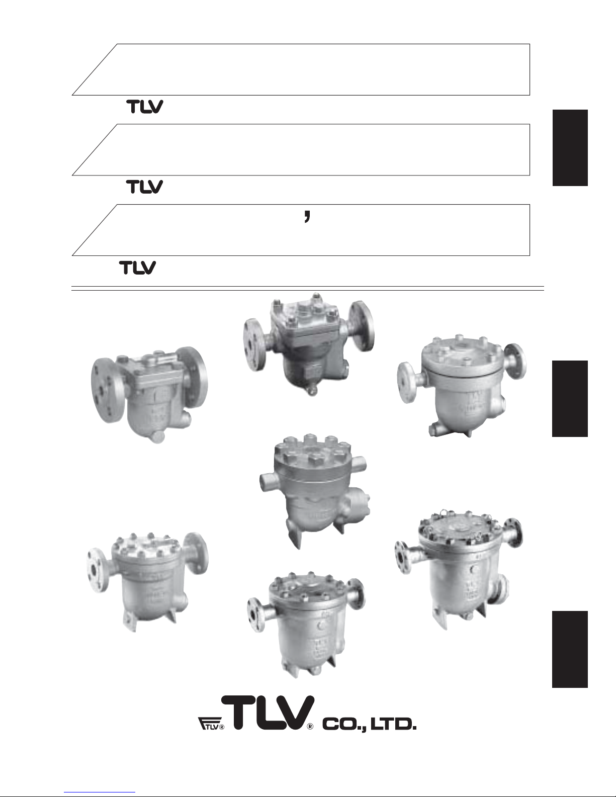
FREE FLOAT TYPE STEAM TRAPS JH-B SERIES
FREISCHWIMMER KONDENSATABLEITER JH-B SERIE
ODWADNIACZE Z PŁYWAKIEM SWOBODNY SERIA JH-B
INSTRUCTION MANUAL
Keep this manual in a safe place for future reference
EINBAU- UND BETRIEBSANLEITUNG
Gebrauchsanleitung leicht zugänglich aufbewahren
MANUEL D UTILISATION
Conserver ce manuel dans un endroit facile d’accès
English
Deutsch
Polski

Introduction
Before beginning installation or maintenance, please read this manual to ensure correct use of
the product. Keep the manual in a safe place for future reference.
The inline repairable JH-B series steam traps with thermostatic bimetal air vent are suitable for a
wide range of applications with small-to-large capacities and pressures up
to 10 MPaG (1500 psig), such as all kinds of heat exchangers, process heaters and coils.
The traps discharge condensate continuously and automatically, at a temperature slightly lower
than saturation temperature.
1 MPa = 10.197 kg/cm
2
, 1 bar = 0.1 MPa
For products with special specifications or with options not included in this manual, contact TLV
for instructions.
The contents of this manual are subject to change without notice.
Einführung
Bitte lesen Sie die Betriebsanleitung vor Einbau und Inbetriebnahme sorgfältig durch und bewahren Sie sie für späteren Gebrauch an einem leicht zugänglichen Ort auf.
Die in der Leitung wartbaren Kugelschwimmer-Kondensatableiter der JH-B Serie, mit thermischem
Bimetall-Entlüfter können für alle Anlagengrößen und mit Betriebsdrücken bis 100 bar ü
eingesetzt werden. Sie eignen sich für Anwendungen, bei denen Kondensat mit geringer Unterkühlung unter Sattdampftemperatur abgeleitet werden soll, insbesondere für Wärmetauscher,
Prozessanlagen und Behälterbeheizungen aller Art.
1 bar = 0,1 MPa
Wenden Sie sich an TLV für Sonderausführungen, die nicht in dieser Einbau- und Betriebs-
anleitung enthalten sind.
Wir behalten uns vor, den Inhalt dieser Betriebsanleitung ohne Ankündigung zu ändern.
Wstęp
Przed montażem należy zapoznać się z niniejszą instrukcją. Należy ją przechowywać w
bezpiecznym miejscu dla wykorzystania w razie potrzeby
Odwadniacze serii JHB są naprawialne bez demontażu z rurociągu. Posiadają odpowietrznik
bimetaliczny i mogą być stosowane dla odwadniania równego rodzaju urządzeń od małych do
dużych wydajności i ciśnień do 10 MPaG (1500 psig), takich jak wymiennik ciepła , wężownice itp.
1 bar = 0,1 MPa
Dla specjalnych zastosowań prosimy o kontakt z firmą TLV
Treść niniejszej instrukcji może się zmieniać bez powiadomienia
Deutsch
Polski
English
― 1 ―
English
―2―
1. Safety Considerations
• Read this section carefully before use and be sure to follow the instructions.
• Installation, inspection, maintenance, repairs, disassembly, adjustment and valve
opening/closing should be carried out only by trained maintenance personnel.
• The precautions listed in this manual are designed to ensure safety and prevent equipment
damage and personal injury. For situations that may occur as a result of erroneous handling,
three different types of cautionary items are used to indicate the degree of urgency and the
scale of potential damage and danger: DANGER, WARNING and CAUTION.
• The three types of cautionary items above are very important for safety; be sure to observe
all of them, as they relate to installation, use, maintenance, and repair. Furthermore, TLV
accepts no responsibility for any accidents or damage occurring as a result of failure to
observe these precautions.
Indicates an urgent situation
which poses a threat of
death or serious injury.
Indicates that there is a
potential threat of death
or serious injury.
WARNING
CAUTION
WARNING
DANGER CAUTION
Indicates that there is a
possibility of injury or equipment/product damage.
NEVER apply direct heat to the float. The float may explode due to
increased internal pressure, causing accidents leading to serious injury
or damage to property and equipment.
Install properly and DO NOT use this product outside the
recommended operating pressure, temperature and other
specification ranges. Improper use may result in such hazards as
damage to the product or malfunctions, which may lead to serious
accidents. Local regulations may restrict the use of this product to below
the conditions quoted.
Take measures to prevent people from coming into direct contact
with product outlets. Failure to do so may result in burns or other injury
from the discharge of fluids.
Use hoisting equipment for heavy objects (weighing approximately
20 kg (44 lb) or more). Failure to do so may result in back strain or other
injury if the object should fall.
Use the eyebolts for removing the cover only; DO NOT use the
eyebolts for hoisting the product. Eyebolts may break under strain,
possibly resulting in serious injury.
DO NOT use this product in excess of the maximum operating
pressure differential. Such use could make discharge impossible.
When disassembling or removing the product, wait until the internal
pressure equals atmospheric pressure and the surface of the
product has cooled to room temperature. Disassembling or removing
the product when it is hot or under pressure may lead to discharge of
fluids, causing burns, other injuries or damage.
Be sure to use only the recommended components when repairing
the product, and NEVER attempt to modify the product in any way.
Failure to observe these precautions may result in damage to the product
or burns or other injury due to malfunction or the discharge of fluids.
Use only under conditions in which no freeze-up will occur. Freezing
may damage the product, leading to fluid discharge, which may cause
burns or other injury.
Use under conditions in which no water hammer will occur. The
impact of water hammer may damage the product, leading to fluid
discharge, which may cause burns or other injury.
Die Schwimmerkugel darf NICHT ERHITZT werden, da sie infolge
erhöhten Innendruckes platzen kann, was schwere Unfälle und
Verletzungen oder Beschädigung von Anlagen zur Folge hat.
1. Sicherheitshinweise
• Bitte lesen Sie dieses Kapitel vor Beginn der Arbeiten sorgfältig durch und befolgen Sie die
Vorschriften.
• Einbau und Ausbau, Inspektion, Wartungs- und Reparaturarbeiten, Öffnen/Schließen von
Armaturen, Einstellung von Komponenten, dürfen nur von geschultem Wartungspersonal
vorgenommen werden.
• Die Sicherheitshinweise in dieser Einbau- und Betriebsanleitung dienen dazu, Unfälle,
Verletzungen, Betriebsstörungen und Beschädigungen der Anlagen zu vermeiden. Für
Gefahrensituationen, die durch falsches Handeln entstehen können, werden drei verschiedene
Warnzeichen benutzt: GEFAHR; WARNUNG; VORSICHT.
• Diese drei Warnzeichen sind wichtig für Ihre Sicherheit. Sie müssen unbedingt beachtet werden,
um den sicheren Gebrauch des Produktes zu gewährleisten und Einbau, Wartung und
Reparatur ohne Unfälle oder Schäden durchführen zu können. TLV haftet nicht für Unfälle oder
Schäden, die durch Nichtbeachtung dieser Sicherheitshinweise entstehen.
Bedeutet, dass eine unmittelbare Gefahr für Leib und
Leben besteht.
Bedeutet, dass die
Möglichkeit der Gefahr für
Leib und Leben besteht.
VORSICHT
WARNUNG
GEFAHR
WARNUNG
VORSICHT
Bedeutet, dass die Möglichkeit
von Verletzungen oder Schäden an
Anlagen oder Produkten besteht.
Die Einbauhinweise beachten und die spezifizierten Betriebsgrenzen
NICHT ÜBERSCHREITEN. Nichtbeachtung kann zu Betriebsstörungen
oder Unfällen führen. Lokale Vorschriften können zur Unterschreitung der
angegebenen Werte zwingen.
In sicherer Entfernung von Auslassöffnungen aufhalten und andere
Personen warnen, sich fernzuhalten. Nichtbeachtung kann zu
Verletzungen durch austretende Fluide führen.
Nur in frostsicherer Umgebung einsetzen. Einfrieren kann das Produkt
beschädigen, was zu Verbrennungen oder Verletzungen durch
austretende Fluide führt.
Nur an Stellen einbauen, an denen kein Wasserschlag eintreten
kann. Wasserschlag kann das Produkt beschädigen und zu
Verbrennungen oder Verletzungen durch austretende Fluide führen.
Für schwere Werkstücke (ca. 20 kg oder mehr) werden Hebezeuge
dringend empfohlen. Nichtbeachtung kann zu Rückenverletzungen oder
Verletzungen durch das herunterfallende Werkstück führen.
Die Ringschrauben nur zum Abheben des Gehäusedeckels benutzen,
NICHT zum Heben des gesamten Produkts. Ringschrauben können
unter Belastung brechen, was zu schweren Unfällen führen kann.
Maximalen Differenzdruck NICHT ÜBERSCHREITEN,
da sonst die Kondensatableitung unmöglich werden kann (Blockage).
Vor Öffnen des Gehäuses und Ausbau von Teilen warten, bis der
Innendruck sich auf Atmosphärendruck gesenkt hat und das
Gehäuse auf Raumtemperatur abgekühlt ist. Nichtbeachtung kann zu
Verbrennungen oder Verletzungen durch austretende Fluide führen.
Zur Reparatur nur Original-Ersatzteile verwenden und NICHT
VERSUCHEN, das Produkt zu verändern. Nichtbeachtung kann zu
Beschädigungen führen, die Betriebsstörungen, Verbrennungen oder
andere Verletzungen durch austretende Fluide verursachen.
Deutsch
― 3 ―
1. INSTRUKCJE BEZPIECZEŃSTWA
• Należy zapoznać się z tą instrukcją szczegółowo i stosować się do zawartych w niej zaleceń.
• Montaż, Inspekcja, Obsługa, Naprawa, Demontaż oraz inne prace związane z otwieraniem i
zamykaniem zaworów powinny być wykonywane tylko przez przeszkolony personel
• Ostrzeżenia wymienione w niniejszym dokumencie zostały opracowane aby zapewnić
bezpieczeństwo, zapobiegać uszkodzeniom urządzeń oraz zranieniom osób obsługujących. Dla
sytuacji które mogą wystąpić w czasie błędnej obsługi, określono 3 główne typy zagrożeń i ich
oznaczenia w zależności od stopnia ryzyka wynikającego z uszkodzeń: ZAGROŻENIE,
OSTRZEŻENIE, UWAGA.
• Trzy typy oznaczeń są bardzo ważne dla bezpieczeństwa i należy pamiętać aby zapoznać się z
nimi, gdyż dotyczą instalacji, stosowania, obsługi i naprawy. Firma TLV nie odpowiada za
jakiekolwiek wypadki i uszkodzenia wynikające z braku stosowania się do tych oznaczeń.
Sygnalizuje nagłą sytuację,
która może grozić śmiercią
lub poważnym zranieniem
Sygnalizuje potencjalne
zagrożenie śmiercią lub
poważnym zranieniem
OSTRZEŻENIE
UWAGA
Ostrzeżenie
UWAGA
Sygnalizuje możliwość
zranienia lub uszkodzenia
urządzenia lub produktu
Należy prawidłowo instalować urządzenie. NIE WOLNO stosować
urządzenia przy parametrach spoza zakresu zalecanych ciśnień oraz
temperatur pracy lub innych ograniczeń podanych w specyfikacji
urządzenia. Niewłaściwe zastosowanie może prowadzić do uszkodzenia
produktu, jego nieprawidłowej pracy,a nawet może prowadzić do
poważnych wypadków. Lokalne przepisy w tym względzie mogą być
bardziej restrykcyjne od podanych w specyfikacjach.
NIDGY nie poddawać pływaka bezpośredniemu oddziaływaniu ciepła.
Może eksplodować na skutek wzrostu ciśnienia wewnętrznego, co może
prowadzić do poważnych zranień lub uszkodzeń mienia i urzadzeń.
Należy podjąć kroki aby zapobiegać możliwości pojawienia się
osób w zasięgu wylotu urządzenia.
Niestosowanie się do powyższego może prowadzić do oparzeń lub
zranień na skutek kontaktu z czynnikiem wypływającym z urządzenia.
Podczas demontażu oraz zdejmowania produktu z instalacji, należy
poczekać do momentu gdy ciśnienie wewnątrz urządzenia zrówna się z
ciśnieniem atmosferycznym i temperatura powierzchni urządzenia spadnie
do temperatury pokojowej. Demontaż i zdejmowanie produktu z instalacji gdy
jest gorące lub pod ciśnieniem może prowadzić do wycieku czynnika powodując
oparzenia lub uszkodzenia.
Należy upewnić się, że stosowane są tylko zalecane elementy do
naprawy urządzenia i NIGDY nie należy dokonywać modyfikacji urządzenia
w jakikolwiek sposób. Nie stosowanie się do powyższego może prowadzić
do uszkodzeń produktu, oparzeń lub innych zranień czy problemów z
działaniem produktu oraz wydostania się czynnika na zewnątrz.
Stosować w warunkach gdy nie występują uderzenia wodne.
Uderzenia wodne mogą doprowadzić do uszkodzenia urządzenia i
w efekcie wydostania się czynnika na zewnątrz co z kolei prowadzi
do zagrożenia oparzeniem lub innym zranieniem.
Stosować urządzenia podnośnikowe dla dużych ciężarów (ważących
około 20 kg (44 lb). Niestosowanie się do tego może prowadzić urazów
ciała i kręgosłupa.
Śrubę oczkową stosować tylko do podnoszenia pokrywy. NIE
STOSOWAĆ śruby oczkowej do podnoszenia całego odwadniacza gdyż
może ulec zerwania pod obciążeniem i doprowadzić do poważnych
zranień.
NIE stosować tego urządzenia dla różnic ciśnień przekraczających
maksymalną roboczą różnicę ciśnień. Odwadniacz w takich
przypadkach nie odprowadza kondensatu.
Stosować tylko w warunkach gdy nie wystąpi zamarzanie.
Zamarzanie produktu może prowadzić do jego uszkodzenia i wydostania
się czynnika na zewnątrz i stworzenia zagrożenia .
Polski
―4―
Niebezpieczeństwo
Deutsch
Français
English
― 5 ―
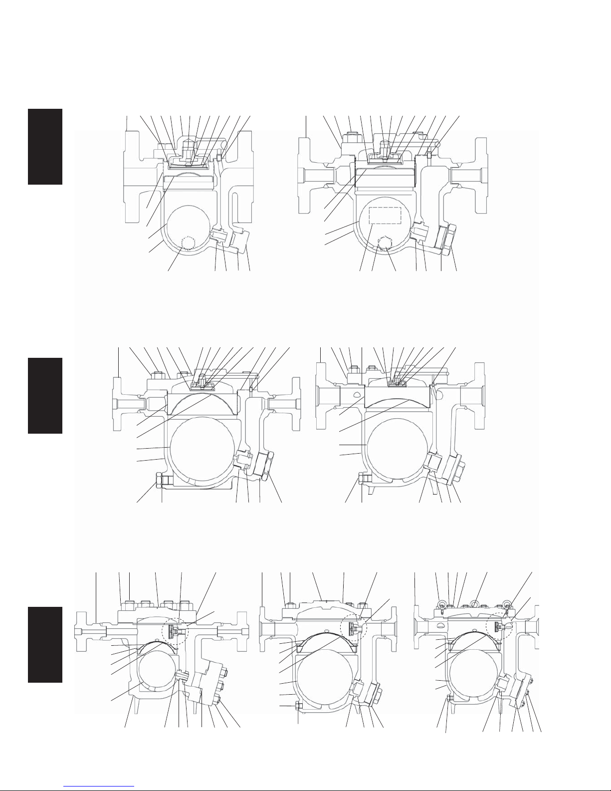
2. Configuration Aufbau Konfiguracja
JH3-B
JH5RL-B
JH5RH-B
JH7.2R-B
JH7.5R-BJH7RH-B JH8R-B
JH7RL-B
JH7RM-B
A
A
A
!0 !1 !6 !7 w@3 @0@1 @2 !9!8 !4!3
!6!1 !7@3w@0 @1@2 !9!8 !4!3
o
i
e
q
o
i
e
q
@6 @7 truy @6 @7 tr u y
!0 w!2 !1 !6 !7!8 !9@0 @1 @2 !3 !5 !4
@3
!5!0!2
!1 @3 w!3!0 !2 !1 @3 w!3!0 !2 !1 @3w!3!2!0
!6!1 !7@3w@0 @1 @2 !9!8 !4!3!0 !2
o
e
q
@4
o
e
q
@4
@6@7 tru
y @6@7 truy
e
q
@4
@5
o
#1
@4
@5
o
#1
truy@8 @9#0
e
q
@7
@4
@5
o
#1
e
q
@7
@6
tru
y
try#4#0@9u
@6
Deutsch
Polski
English
―6―
No.
1
2
3
4
5
6
7
8
9
10
11
12
No.
13
14
15
16
17
18
19
20
21
22
23
24
Body
Cover
Float
Orifice
Orifice Gasket
Orifice Plug or Outlet Cover
Plug or Outlet Cover Gasket
Float Cover
Screen
Flange or Socket
Cover Bolt
Cover Nut
Cover Gasket
Connector
Connector Gasket
Snap Ring
Air Vent Case
Bimetal Plate
Air Vent Screen
Air Vent Valve Seat
Air Vent Valve Plug
Snap Ring
Nameplate
Screen Holder
Description
Description
No.
25
26
27
28
29
30
31
32
33
34
Snap Ring
Drain Plug Gasket*
Drain Plug*
Orifice Locknut
Outlet Cover Bolt
Outlet Cover Nut
Screen Holder Retainer
Air Vent Guide Gasket
Air Vent Guide
Eye Bolt
Description
* Option for JH3-B, JH5RL-B, JH5RH-B
Nr.
1
2
3
4
5
6
7
8
9
10
11
12
Nr.
13
14
15
16
17
18
19
20
21
22
23
24
Gehäuse
Gehäusedeckel
Schwimmerkugel
Ventilsitz
Ventilsitzdichtung
Ventilsitzstopfen oder Ventilsitzdeckel
Stopfendichtung oder Deckeldichtung
Schwimmerabdeckung
Schmutzsieb
Flansch oder Schweißmuffe
Gehäuseschraube
Gehäusemutter
Gehäusedichtung
Verbindungshülse
Verbindungshülsedichtung
Spannring
Entlüftergehäuse
Bimetallscheibe
Entlüfter-Schmutzsieb
Entlüfterventilsitz
Entlüfterventilstopfen
Spannring
Typenschild
Siebhalterung
Bauteil
Bauteil
Nr.
25
26
27
28
29
30
31
32
33
34
Spannring
Stopfendichtung*
Entwässerungsstopfen*
Verschlussmutter
VentilsitzdeckelsFhraube
Ventilsitzdeckelmutter
Abstandsring
Entlüfterdichtung
Entlüfterführung
RingsFhraube
Bauteil
* Option für JH3-B, JH5RL-B, JH5RH-B
No.
1
2
3
4
5
6
7
8
9
10
11
12
No.
13
14
15
16
17
18
19
20
21
22
23
24
Korpus
Pokrywa
Pływak
Kryza
Uszczelka pokrywy
Korek pokrywy
Uszczelka
Pokrywa pływaka
Filtr
Kołnierz lub króciec spawany
Śruba
Nakrętka
Uszczelka pokrywy
Rurka
Uszczelka
Klips spreżynujący
Prowadnica odpowietrznika
Dysk bimetalu
Filtr
Gniazdo odpowietrznika
Zawór odpowietrznika
Pierścień
Tabliczka znamionowa
Docisk filtra
Opis
Opis
No.
25
26
27
28
29
30
31
32
33
34
Pierścień
Uszczelka korka*
Korek spustowy*
Nakrętka kryzy
Śruba pokrywy kryzy
Nakrętka pokrywy kryzy
Docisk filtra
Uszczelka prowadnicy odp.
Prowadnica odpowietrznika
Śruba oczkowa
Opis
* Option pour JH3-B, JH5RL-B, JH5RH-B
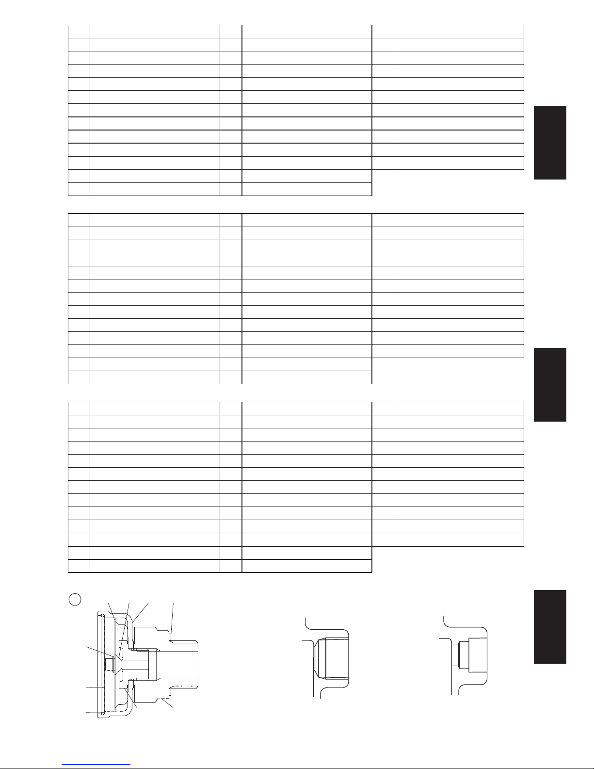
A
Connection Anschluss Przyłącze
Screwed
Muffe
Gwint
Socket Weld
Schweißmuffe
Spawane SW
Flanged: see page 5 Flansch: siehe Seite 5 Kołnierz patrz strona 5
!8 @1 !7 #2
@2
!9
!6
@0 #3
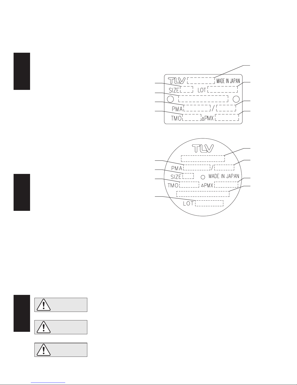
3. Specifications Technische Daten Specyfikacja
Refer to the product nameplate for detailed specifications.
Die technischen Daten stehen auf dem Typenschild.
Odnosi się do informacji zawartych na tabliczce znamionowej danego urządzenia
* Maximum allowable pressure (PMA) and maximum allowable temperature (TMA) are
PRESSURE SHELL DESIGN CONDITIONS, NOT OPERATING CONDITIONS.
** "Valve No." is displayed for products with options. This item is omitted from the
nameplate when there are no options.
* Maximal zulässiger Druck (PMA) und maximal zulässige Temperatur (TMA) sind
AUSLEGUNGSDATEN, NICHT BETRIEBSDATEN.
** Die "Valve No." wird angegeben bei Typen mit Optionen. Bei Typen ohne Optionen bleibt
diese Stelle frei.
G Production Lot No.
Fertigungslos-Nr.
Numer produkcyjny N°
H Valve No.**
Numer zaworu
C Maximum Allowable Pressure*
Maximal zulässiger Druck*
Maksymalne dopuszczalne ciśnienie*
F Maximum Operating Temperature
Maximale Betriebstemperatur
Maksymalna temperatura pracy
D Maximum Allowable Temperature* TMA
Maximal zulässige Temperatur* TMA
Maksymalna dopuszczalna temperatura* TMA
A Model
E Maximum Differential Pressure
Maximaler Differenzdruck
Maksymalna różnica ciśnień
Typ
Typ
B Nominal Diameter
Größe/DN
Średnica przyłącza/DN
B
A
G
D
E
A
D
E
H
H
C
F
C
B
F
G
VORSICHT
UWAGA
To avoid malfunctions, product damage, accidents or serious injury install
properly and, DO NOT use this product outside the specification range. Local
regulations may restrict the use of this product to below the conditions quoted.
Die Einbauhinweise beachten und die spezifizierten Betriebsgrenzen NICHT
ÜBERSCHREITEN. Nichtbeachtung kann zu Betriebsstörungen oder Unfällen
führen. Lokale Vorschriften können zur Unterschreitung der angegebenen
Werte zwingen.
NIE WOLNO stosować urządzenia przy parametrach spoza zakresu zalecanych
ciśnień oraz temperatur pracy lub innych ograniczeń podanych w specyfikacji
urządzenia. Niewłaściwe zastosowanie może prowadzić do uszkodzenia
produktu, jego nieprawidłowej pracy, a nawet może prowadzić do poważnych
wypadków. Lokalne przepisy w tym względzie mogą być bardziej restrykcyjne
od tych podanych w specyfikacjach.
CAUTION
Deutsch
Français
English
7
* Maksymalne dopuszczalne cisnienie (PMA) oraz maksymalna dopuszczalna temperatura
(TMA) są dopuszczalnymi parametrami korpusu a nie parametrami pracy .
** Numer zaworu jest pokazany w przypadku opcji. Brak gdy nie ma opcji

English
―8―
5. Piping Arrangement
Requirement
Install a catchpot with the
proper diameter.
Diameter is too
small.
Diameter is too
small and inlet
protrudes into pipe.
Rust and scale
flow into the trap
with the
condensate.
Condensate
collects in the
pipe.
Continued page 9
Make sure the flow of
condensate is not
obstructed.
To prevent rust and scale
from flowing into the trap,
connect the inlet pipe
25 - 50 mm (1 - 2 in) above
the base of the T - pipe.
When installing on the
blind end, make sure
nothing obstructs the flow
of condensate.
Correct
Incorrect
Allowable
Horizontal lnclination
Allowable
Vertical lnclination
1.
Before installation, be sure to remove all protective seals.
2.
Before installing the trap, blow out the inlet piping to remove all dirt and oil.
3. When hoisting the product, hang the rope around the inlet/outlet as close to the body as
possible.
4. Install the steam trap within the allowable inclination, as shown below. Also make sure that
the arrow mark on the body corresponds with the direction of flow.
5.
Install the trap in the lowest part of the pipeline or equipment so the condensate flows naturally
into the trap by gravity. The inlet pipe should be as short and have as few bends as possible.
6.
Support the pipes properly within 800 mm (2.5 ft) on either side of the trap.
7.
Install a bypass valve to discharge condensate, and inlet and outlet valves to isolate the trap in
the event of trap failure or when performing maintenance.
8.
Install a check valve at the trap outlet whenever more than one trap is connected to the
condensate collection pipeline.
9.
The use of unions is recommended to facilitate connection and disconnection of screwed
models.
4. Proper Installation
• Installation, inspection, maintenance, repairs, disassembly, adjustment
and valve opening/closing should be carried out only by trained
maintenance personnel.
• Use the eyebolts for removing the cover only; DO NOT use the eyebolts
for hoisting the product.
• Take measures to prevent people from coming into direct contact with
product outlets.
• Install for use under conditions in which no freeze-up will occur.
• Install for use under conditions in which no water hammer will occur.
CAUTION
5˚
5˚
5˚ 5˚
English
― 9 ―
1. Is the pipe diameter suitable?
2. Has the trap been installed within the allowable inclination and with the arrow on the body
pointing in the direction of flow?
3. Has sufficient space been secured for maintenance?
4. Have maintenance valves been installed at the inlet and outlet? If the outlet is subject to
back pressure, has a check valve been installed?
5. Is the inlet pipe as short as possible, with as few bends as possible, and installed so that the
condensate will flow naturally down into the trap?
6. Has the piping work been done with the proper methods, as shown in the table on page 8?
Check to make sure that the pipes connected to the trap have been installed properly.
Operational inspections should be performed at least twice per year, or as called for by trap
operating conditions. Steam trap failure may result in temperature drop in the equipment, poor
product quality or losses due to steam leakage.
6. Inspection and Maintenance
WARNING
NEVER apply direct heat to the float. The float may explode due to
increased internal pressure, causing accidents leading to serious injury or
property and equipment damage.
• Installation, inspection, maintenance, repairs, disassembly, adjustment
and valve opening/closing should be carried out only by trained
maintenance personnel.
• Before attempting to open the trap, close the inlet and outlet isolation
valves and wait until the trap has cooled completely. Failure to do so
may result in burns.
• Be sure to use the proper components and NEVER attempt to modify
the product.
CAUTION
Body, Cover(s)
Gaskets
Bimetal Plate
Air Vent Valve (and Seat)
Screen(s)
Float
Orifice Opening
Check inside for damage, dirt, grease, oil film, rust or scale
Check for warping or damage
Check for damage
Check for damage
Check for clogging, corrosion or damage
Check for deformation, damage, oil film or water inside
Check for rust, scale, oil film, wear or damage
Parts Inspection Procedure

English
―10―
Disassembly/Reassembly (to reassemble, follow procedures in reverse)
JH3-B
JH5RL-B
JH5RH-B
JH7RL-B
JH7RM-B
JH7.2R-B
* Option
**
The entire unit may be removed and replaced at the Air Vent Guide 33 with an open wrench
*** Must remove Air Vent Guide 33 before this part can be removed or inserted
JH7RH-B
Part & No.
JH7.5R-B
JH8R-B
During Disassembly During Reassembly
Drain Plug 27
Use a wrench to remove
Coat threads with anti-seize and
tighten to the proper torque
Drain Plug Gasket 26
Remove gasket and clean
sealing surfaces
Use a wrench to remove
Replace with a new gasket, coat
surfaces with anti-seize
Coat threads with anti-seize and
tighten to the proper torques
Cover Nut 12
Use a wrench to remove
Coat threads with anti-seize and
tighten to the proper torque
Cover 2
Remove (use all 4 eye bolts
for JH8R-B to hoist the cover)
Align cover with the connector or the
arrow on the body and attach
Cover Gasket 13
Cover Bolt 11
Remove gasket and clean
sealing surfaces
Replace with a new gasket, do not
apply anti-seize
Connector 14
Remove the connector Insert the connector
Connector
Gasket 15
Remove gasket and clean
sealing surfaces
Replace with a new gasket, do not
apply anti-seize
Snap Ring 16 Use appropriate pliers Insert securely into groove
Air Vent Screen 19
Remove being careful not
to misshape
Replace being careful not to misshape
Bimetal Unit 18, 21, 22
Remove bimetal unit from cover
Reinsert in the proper orientation
Air Vent Valve Seat 20
Use a wrench to remove Tighten to the proper torque
Air Vent Case 17
Remove from cover Place in cover
Air Vent Guide 33 Use a wrench to remove
Tighten to the proper torque
Air Vent Guide
Gasket 32
Remove gasket and clean
sealing surfaces
Replace with a new gasket, coat
surfaces with anti-seize
Screen 9 &
Float Cover 8
Lift straight up
Align arrows and insert, insert
tab on bottom into guide on body
and push in until top is flush
Snap Ring 25 Use appropriate pliers Insert securely into groove
Screen 9
Lift straight up while turning
Place screen holder on ledge inside
body, round side up; place screen
holder retainer next (if applicable),
followed by screen
Screen Holder Retainer 31
Lift straight up
Screen Holder 24 Remove without bending
Float 3
Remove, careful not to
scratch grounded surface
Insert into body, being careful not to
scratch its grounded surface
Orifice Plug 6
Use a wrench to remove
Coat threads with anti-seize and
tighten to the proper torque
Orifice Plug Gasket 7
Remove gasket and clean
sealing surfaces
Replace with a new gasket, coat
surfaces with anti-seize
Outlet Cover Nut 30
Use a wrench to remove
Coat threads with anti-seize and
tighten to the proper torque
Outlet Cover 6
Remove Attach
Outlet Cover
Gasket 7
Remove gasket and clean
sealing surfaces
Replace with a new gasket, do not
apply anti-seize
Orifice Locknut 28
Use a wrench to remove
(may require extension bar)
Coat threads with anti-seize and tighten
to the proper torque (see page 11)
Orifice 4
Use a wrench to remove
Coat threads with anti-seize and
tighten to the proper torque
Remove from interior Fix with Orifice Locknut (see page 11)
Orifice Gasket 5
Remove gasket and clean
sealing surfaces
Replace with a new gasket, coat
surfaces with anti-seize
Replace with a new gasket (see page 11)
* *
* *
*********
*********
*********
** ** **
** ** **
** ** **
** ** **
** ** **
** ** **
** ** **

English
―11―
Parts &
Number
Model
Cover Bolt / Nut 12
Orifice 4
Orifice Plug 6
Drain Plug* 27
Air Vent Valve Seat 20
Model
Cover Nut 12
Orifice 4
Orifice Plug 6
Outlet Cover Nut 30
Drain Plug 27
Orifice Locknut 28
Air Vent Valve Seat 20
Air Vent Guide 33
Model
Cover Nut 12
Orifice 4
Orifice Plug 6
Outlet Cover Nut 30
Drain Plug 27
Air Vent Valve Seat 20
Air Vent Guide 33
(37)
(22)
(59)
(26)
(22)
(81)
(210)
(310)
(73)
(22)
(110)
(260)
(510)
(73)
(22)
50
30
80
35
30
110
280
420
100
30
150
350
700
100
30
17
10
24
21
17
22
26
50
26
19
24
38
46
26
19
()
()
()
()
()
()
()
()
()
()
()
()
()
()
()
()
(1)
()
(1)
()
()
()
()
(1)
()
()
(1)
()
(1)
()
()
()
()
(1)
()
()
()
()
()
()
()
()
()
()
(1)
()
()
JH3-B JH5RL-B
JH7.5R-B
JH8R-B
JH5RH-B
JH7RL-B JH7RM-B JH7RH-B
Tightening Torque and Distance Across Flats
/
32
21
/
32
21
/
32
21
/
32
21
/
8
3
/
16
13
/
8
7
/
16
15
/
16
13
/
16
13
/
16
13
/
4
3
/
4
3
/
4
3
/
4
3
/
4
3
/
4
3
/
4
3
/
4
3
/
2
1
1
/
2
1
1
/
2
1
1
/
4
1
1
/
8
3
2
/
32
13
1
(lbf.ft)N.m mm (in)
(81)
(100)
(130)
(26)
(22)
(150)
(210)
(310)
(73)
(22)
(150)
(440)
(590)
(73)
(22)
(110)
110
140
180
35
30
200
280
420
100
30
200
600
800
100
30
150
21
17
38
21
19
24
26
50
26
19
30
46
46
26
19
30
(125)
(100)
(130)
(26)
(22)
(510)
(150)
(185)
(22)
(73)
(330)
(730)
(115)
(73)
(22)
(110)
170
140
180
35
30
700
200
250
30
100
450
1000
160
100
30
150
24
17
38
21
19
46
30
32
19
24
36
60
24
26
19
50
If drawings or other special documentation were supplied for the product, any torque given there
takes precedence over values shown here.
JH7.2R-B
(lbf.ft)N.m mm (in) (lbf.ft)N.m mm (in)
1 N.m 10 k g・cm
〜
〜
/
16
15
/
16
15
/
16
15
/
16
15
/
16
13
1
/
16
13
1
/
16
13
1
/
16
13
1
/
16
3
1
/
16
3
1
/
16
3
1
1
/
32
31
1
/
32
31
/
16
15
NOTES for JH7RH-B:
Special Points Pertaining to Orifice and Orifice Gasket Reassembly
Follow the steps below when inserting the orifice into the body in order to ensure that the gasket
does not fall off and is inserted correctly without protruding from the groove.
1. First, insert the orifice alone into the orifice-housing section of the body, in order to ascertain
how much of it should be sticking out.
2. Take the orifice out again, and then fill the groove in the orifice with water and insert the
gasket. The surface tension of the water will now hold the gasket in place, and it will not fall out
even if the orifice is pointed downwards.
3. Without altering anything, insert it into the orifice-housing section of the body and check to
make sure that the amount of orifice sticking out of the body is the same as the amount that
was sticking out when only the orifice was inserted in step 1.
4. Hold it in that position by hand and, after hand-tightening the orifice locknut from the outlet
side, hold the orifice in place from the body float chamber side using a drive wrench and then
tighten the orifice locknut to the proper torque using a torque wrench.
Special Points Pertaining to Cover and Outlet Cover Reassembly
1. After operation following disassembly
and reassembly, it is recommended that
the trap be let to sit for a day and then
receive additional tightening.
2. Using the tightening torques for the
cover nuts and outlet cover nuts as a
reference, tighten until the cover and
outlet cover gaps are uniform. The gaps
should be 1.5 mm ( ”) or less.
Cover or
Outlet Cover
Body
1.5mm
/
16
1
/
16
1
( ”)
* Option for JH3-B, JH5RL-B, JH5RH-B
/
32
31
1

Instructions for Plug / Holder Disassembly and Reassembly
The seal on the threaded plugs/holders found on TLV products is formed by a flat metal
gasket. There are various installation orientations for the gaskets, such as horizontal,
diagonal and downward, and the gasket may be pinched in the thread recesses during
assembly.
Instructions for Disassembly and Reassembly
1 Remove the plug/holder using a tool of the specified
size (distance across flats).
2 The gasket should not be reused. Be sure to
replace it with a new gasket.
3 Clean the gasket surfaces of the plug/holder and the
product body using a rag and/or cleaning agents, then
check to make sure the surfaces are not scratched or
deformed.
4 Coat both the gasket surface of the plug/holder and
the threads of the plug/holder with anti-seize, then
press the gasket onto the center of the gasket
surface of the plug/holder, making sure the
anti-seize affixes the gasket tightly to the
plug/holder. Check to make sure the gasket is not
caught in the recesses of the threads.
5 Hold the plug/holder upside down to make sure that
the anti-seize makes the gasket stick to the
plug/holder even when the plug/holder is held
upside down.
6 Screw the plug/holder by hand into the product body
while making sure that the gasket remains tightly
affixed to the center of the gasket surface of the
plug/holder. Make sure the entire gasket is making
contact with the gasket surface of the product body.
It is important at this point to make sure the gasket
is not pinched in the thread recesses of the
plug/holder.
7 Tighten the plug/holder to the proper torque.
8 Next, begin the supply of steam and check to make sure there is no leakage from the part
just tightened. If there is leakage, immediately close the inlet valve and, if there is a bypass
valve, take the necessary steps to release any residual pressure. After the surface of the
product cools to room temperature, repeat the procedure beginning from step
1 .
3
5
6
Gasket
Do not pinch gasket
in thread recesses
4
Coat with anti-seize
Gasket Surface
English
―12―

English
―13―
8. Operational Check
Normal: Condensate is discharged continuously with flash steam and the sound
of flow can be heard. If there is very little condensate, there is almost no
sound of flow.
Blocked: No condensate is discharged. The trap is quiet and makes no noise,
and the surface temperature of the trap is low.
Blowing: Live steam continually flows from the outlet and there is a continuous
metallic sound.
Live steam is discharged through the trap outlet together with the
condensate and there is a high-pitched sound.
A visual inspection can be carried out to aid in determining the necessity for immediate
maintenance or repair, if the trap is open to atmosphere. If the trap does not discharge to
atmosphere, use diagnostic equipment such as TLV TrapMan or TLV Pocket TrapMan (within
their pressure and temperature measurement range).
Flash Steam
White jet
containing
water droplets
Live Steam Leakage
Clear, slightly
bluish jet
(When conducting a visual inspection, flash steam is sometimes mistaken for steam leakage. For
this reason, the use of a steam trap diagnostic instrument such as TLV TrapMan is highly
recommended.)
Steam
Leakage:
Maintenance Kit: M
Repair Kit: R
Orifice 4
Orifice Gasket 5
Orifice Plug Gasket or
Outlet Cover Gasket 7
Float Cover 8
Screen 9
Cover Gasket 13
Connector Gasket 15
Snap Ring 16
Air Vent Case 17
Bimetal Plate 18
Air Vent Screen 19
Air Vent Valve Seat 20
Air Vent Valve Plug 21
Snap Ring 22
Drain Plug Gasket* 26
Orifice Locknut 28
Air Vent Guide Gasket 32
Maintenance parts and repair parts are available from TLV only in kits, as shown below.
7. Maintenance Parts and Repair Parts
JH3-B
MR
JH5RL-B
JH5RH-B
JH7RL-B
JH7RM-B
JH7.2R-BJH7RH-B JH7.5R-B JH8R-B
MRMRMRMRMRMR
Float Replacement Replacement floats are available for all models above.
* Option for JH3-B, JH5RL-B, JH5RH-B

9. Troubleshooting
If the expected performance is unachievable after installation of the steam trap, read chapters 4
and 5 again and check the following points for appropriate corrective measures.
NOTE: When replacing parts with new, use the parts list on page 13 for reference, and replace with
parts from the respective replacement parts kits.
Problem
No condensate
is discharged
(blocked) or
discharge is
poor
Steam is
discharged or
leaks from the
trap outlet
(blowing)
(steam leakage)
Steam leaks from
a place other
than the trap
outlet
Float is damaged or filled with condensate
The trap operating pressure exceeds the maximum
specified pressure, or there is insufficient pressure
differential between the trap inlet and outlet
Compare specifications
and actual operating
conditions
Steam locking has occurred
Blowdown through the
bypass or close the trap
inlet valve and allow the
trap to cool
Rust and scale have accumulated around the
valve seat or under the float
Clean
Deterioration of or damage to gaskets
Leakage from eroded cavities of body or cover
Improper tightening torque for cover was used
Replace the gaskets
Replace the trap
Float is
frequently
damaged
Water hammer occurs Examine the piping for
problems that can cause
water hammer
Orifice is damaged Replace with new orifice
Float is deformed or coated with scale Clean or replace the float
The bimetal is damaged Replace with new bimetal
Trap is installed above the maximum allowable
inclination angle
Correct the installation
Vibration of trap occurs Lengthen inlet piping,
then fasten it securely
The bimetal air vent valve surface and/or the air
vent valve seat has a build-up or is scratched
Clean or replace with
new bimetal and/or air
vent valve seat
Replace the float
Cause
Remedy
Orifice, screen or piping are clogged with rust or
scale
Tighten to the proper
torque
The bimetal is damaged
Replace with new bimetal
Clean
English
―14―

1.
Vor dem Einbau die Transport-Schutzkappen entfernen.
2.
Vor Einbau Leitung durchblasen, um Öl und Verschmutzungen zu entfernen.
3. Zum Heben des Produkts das Seil um die Einlass/Auslass-Stutzen so nahe wie möglich am
Gehäuse schlingen.
4. Die Kondensatableiter sind so einzubauen, dass die nachfolgend gezeigten Schräglagentoleranzen nicht überschritten werden und der Pfeil auf dem Gehäuse in Durchflussrichtung zeigt.
5.
Die Zuführleitung sollte kurz sein, so wenig Krümmer wie möglich aufweisen und ist so zu
verlegen, dass das Kondensat durch Schwerkraftwirkung dem KA zufließen kann.
6.
Die Kondensatleitung im Abstand von maximal 800 mm vor und hinter dem KA abstützen.
7.
Für Wartung und Inspektion Absperrorgane vor und hinter dem Kondensatableiter, sowie eine
Umgehungsleitung zur Notentwässerung vorsehen.
8.
Falls die Auslassleitung in einen Tank oder eine Kondensatrückführleitung mündet, oder falls
mehrere Kondensatableiter an eine gemeinsame Leitung angeschlossen sind, muss ein
Rückschlagventil hinter jedem Kondensatableiter eingebaut werden.
9.
Bei Muffenanschluss wird empfohlen, Rohrverschraubungen vor und hinter dem KA
anzubringen.
4. Einbauhinweise
•
Einbau und Ausbau, Inspektion, Wartungs- und Reparaturarbeiten,
Öffnen/Schließen von Armaturen, Einstellung von Komponenten dürfen nur
von geschultem Wartungspersonal vorgenommen werden.
•
Die Ringschrauben nur zum Abheben des Gehäusedeckels benutzen,
NICHT zum Heben des gesamten Produkts.
•
In sicherer Enfernung von Auslassöffnungen aufhalten und andere Personen
warnen, sich fern zu halten.
•
Kondensatableiter in frostsicherer Umgebung einbauen.
•
Kondensatableiter nur dort einbauen, wo kein Wasserschlag eintreten kann.
VORSICHT
5. Rohrleitungsführung
Vorschrift
Kondensatstutzen mit ausreichendem Durchmesser
einbauen.
Durchmesser
zu klein.
Durchmesser zu klein
und Abflussrohr ragt in
Rohrleitung hinein.
Rost und sonstige
Ablagerungen gelangen
mit dem Kondensat in
den KA.
Kondensat
sammelt sich in
Rohrleitung an.
Für ungehinderten
Kondensatzufluss
sorgen.
Um Rost und sonstige Ablagerungen vom KA fernzuhalten
muss die Zuleitung 25 - 50 mm
über dem Deckel des Stutzens
angeschlossen werden.
Bei Einbau an Leitungsenden ist
die nebenstehende Anschlu
ss
art
vorzusehen, damit das Kondensat
ungehindert abfließen kann.
Richtig
Falsch
Horizontale Toleranz Vertikale Toleranz
Fortsetzung Seite 16
5˚
5˚
5˚ 5˚
Deutsch
―15―

1. Ist die Nennweite groß genug?
2. Wurde der KA horizontal, bzw. innerhalb der Schräglagentoleranz und mit dem Pfeil in
Durchflussrichtung eingebaut?
3. Ist genügend Platz für Wartungsarbeiten vorhanden?
4. Wurden vor und hinter dem KA Absperrarmaturen eingebaut? Falls Gegendruck besteht,
wurde ein Rückschlagventil eingebaut?
5. Ist die Zuleitung so kurz wie möglich, hat sie so wenig Krümmer wie möglich und kann das
Kondensat durch Schwerkraft zufließen?
6. Wurden die Rohrleitungen so ausgeführt, wie auf Seite 15 beschrieben?
Stellen Sie sicher, dass die Rohrleitungsarbeiten richtig ausgeführt wurden und dass der KA wie
beschrieben eingebaut wurde:
Gehäuse, Deckel
Dichtungen
Bimetallscheibe
Schmutzsiebe
Schwimmerkugel
Ventil-Öffnung
Auf Ablagerungen, Rost, Schmutz, Ölfilm prüfen
Auf Verformung oder Beschädigung prüfen
Auf Beschädigung prüfen
Auf Verstopfung, Ablagerungen, Beschädigung prüfen
Auf Verformung, Beschädigung oder Wasser in der Kugel prüfen
Auf Ablagerungen, Rost, Schmutz, Ölfilm prüfen
Überprüfung der Einzelteile
Es wird empfohlen, mindestens zweimal pro Jahr oder, je nach Betriebsweise, in kürzeren
Zeitabständen eine Inspektion durchzuführen.
6. Inspektion und Wartung
WARNUNG
Die Schwimmerkugel darf NICHT ERHITZT werden, da sie infolge erhöhten
Innendruckes platzen kann, was schwere Unfälle und Verletzungen oder
Beschädigung von Anlagen zur Folge hat.
•
Einbau und Ausbau, Inspektion, Wartungs- und Reparaturarbeiten,
Öffnen/Schließen von Armaturen, Einstellung von Komponenten dürfen nur
von geschultem Wartungspersonal vorgenommen werden.
• Vor dem Öffnen des Kondensatableiters sind die Absperrarmaturen auf
beiden Seiten zu schließen. Gehäuse auf Raumtemperatur abkühlen
lassen. Nichtbeachtung kann zu Verbrennungen führen.
• Zur Reparatur nur Original-Ersatzteile verwenden und NICHT
VERSUCHEN, das Produkt zu verändern.
VORSICHT
Deutsch
―16―

Deutsch
―17―
Ausbau und Einbau der Teile (Einbau erfolgt in umgekehrter Reihenfolge)
JH3-B
JH5RL-B
JH5RH-B
JH7RL-B
JH7RM-B
JH7.2R-B
* Option
**
Die gesamte Einheit kann am Entlüfterführung mit einem Gabelschlüssel entnommen und ausgetauscht werden.
***
Zum Ausbau und Einbau dieses Teils muss erst Entlüfterführung 33 abgenommen werden.
JH7RH-B
Bauteil & Nr.
JH7.5R-B
JH8R-B
Ausbau
Einbau
Entwässerungsstopfen 27
Gabel- oder Ringschlüssel
verwenden
Gewinde schmieren, Anzugsmoment
beachten
Stopfendichtung 26
Dichtung entfernen und
Dichtflächen reinigen
Dichtung erneuern, mit Schmiermittel
bestreichen
Gehäusemutter 12
Gehäuseschraube 11
Gabel- oder Ringschlüssel
verwenden
Gabel- oder Ringschlüssel
verwenden
Gewinde schmieren, Anzugsmoment
beachten
Gewinde schmieren, Anzugsmoment
beachten
Gehäusedeckel 2
ausbauen (alle vier
Ringschrauben von JH8R-B
zum Anheben benutzen)
Deckel so aufsetzen, dass
Verbindungshülse passt
Gehäusedichtung 13
Dichtung entfernen und
Dichtflächen reinigen
Dichtung erneuern, nicht mit
Schmiermittel bestreichen
Verbindungshülse 14 Hülse abnehmen Hülse einsetzen
Dichtung
Verbindungshülse 15
Dichtung entfernen
und Dichtflächen reinigen
Dichtung erneuern, nicht mit
Schmiermittel bestreichen
Spannring 16
mit geeigneter Zange zusammendrücken und aus Rille ziehen
einsetzen und in Rille einrasten
EntlüfterSchmutzsieb 19
Darauf achten, das Sieb nicht
zu verformen
Darauf achten, das Sieb nicht zu
verformen
Bimetall-Packung
18, 21, 22
Bimetall-Packung aus
Gehäusedeckel herausnehmen
beim Einsetzen auf richtige Ausrichtung
achten
Entlüfterventilsitz 20
Gabel- oder Ringschlüssel
verwenden
Anzugsmoment beachten
Entlüftergehäuse 17
aus Gehäusedeckel
herausnehmen
in Gehäusedeckel einsetzen
Entlüfterführung 33
Gabel- oder Ringschlüssel
verwenden
Anzugsmoment beachten
Entlüfterdichtung 32
Dichtung entfernen und
Dichtflächen reinigen
Dichtung erneuern, mit Schmiermittel
bestreichen
Schmutzsieb 9 &
Schwimmerabdeckung 8
Nach oben abheben
mit Pfeil auf Schwimmer-Abdeckung (wie
Pfeil auf Gehäuse und Nocke) in Führung im
Gehäuse einsetzen bis Sieboberkante mit
Gehäuseoberkante übereinstimmt
Spannring 25
mit geeigneter Zange zusammendrücken und aus Rille ziehen
einsetzen und in Rille einrasten
Schmutzsieb 9
Drehend nach oben abziehen
Siebhalterung mit Rundung nach oben
auf Gehäusevorsprung aufsetzen, dann
Abstandsring, falls vorhanden, und
Schmutzsieb
Abstandsring 31
Nach oben abheben
Siebhalterung 24
Herausnehmen, nicht verbiegen
Schwimmerkugel 3
Gabel- oder Ringschlüssel
verwenden
Gewinde schmieren, Anzugsmoment
beachten
Ventilsitzstopfen 6
Dichtung entfernen und
Dichtflächen reinigen
Dichtung erneuern, mit Schmiermittel
bestreichen
Stopfendichtung 7
Gabel- oder Ringschlüssel
verwenden
Gewinde schmieren, Anzugsmoment
beachten
Ventilsitzdeckelmutter 30
Deckel abnehmen Deckel aufsetzen
Ventilsitzdeckel 6
Dichtung entfernen und
Dichtflächen reinigen
Dichtung erneuern, nicht mit
Schmiermittel bestreichen
Deckeldichtung 7
Gabel- oder Ringschlüssel
verwenden (u.U. wird eine
Verlängerungsschiene benötigt)
Gewinde schmieren, Anzugsmoment
beachten
(siehe Seite 18)
Verschlussmutter 28
Gabel- oder Ringschlüssel
verwenden
Gewinde schmieren, Anzugsmoment
beachten
Ventilsitz 4
aus dem Inneren entnehmen
mit Ventilsitz-Verschlussmutter anziehen
(siehe Seite 18)
Gabel- oder Ringschlüssel
verwenden
Gewinde schmieren, Anzugsmoment
beachten
Ventilsitzdichtung 5
Dichtung entfernen und
Dichtflächen reinigen
Dichtung erneuern, mit Schmiermittel
bestreichen
Dichtung erneuern (siehe Seite 18)
* *
* *
******
**
****
******
******
******
******
******
*** ******
***
******
****** ***

Bauteil
& Nr.
Typ
Gehäusedeckelbolzen / -mutter 12
Ventilsitz 4
Ventilsitzstopfen 6
Entwässerungsstopfen* 27
Entlüfterventilsitz 20
Typ
Gehäusedeckelbolzen / -mutter 12
Ventilsitz 4
Ventilsitzstopfen 6
Ventilsitzdeckelmutter 30
Entwässerungsstopfen 27
Verschlussmutter 28
Entlüfterventilsitz 20
Entlüfterführung 33
JH3-B JH5RL-B
JH7.5R-B JH8R-B
JH5RH-B JH7RL-B JH7RM-B
JH7RH-B
Anzugsmomente und Schlüsselweiten
50
30
80
35
30
700
200
250
30
100
N.m
17
10
24
21
17
46
30
32
19
24
mm
Falls Zeichnungen oder andere spezielle Dokumente mit dem Produkt geliefert wurden, haben Angaben über
Anzugsmomente in diesen Unterlagen Vorrang vor den hier gezeigten Anzugsmomenten.
JH7.2R-B
110
140
180
35
30
150
350
700
100
30
N.m
21
17
38
21
19
24
38
46
26
19
mm
170
140
180
35
30
200
600
800
100
30
150
N.m
24
17
38
21
19
30
46
46
26
19
30
mm
110
280
420
100
30
450
1000
160
100
30
150
N.m
22
26
50
26
19
36
60
24
26
19
30
mm
200
280
420
100
30
N.m
24
26
50
26
19
mm
Hinweise für JH7RH-B:
Besondere Punkte zum Zusammenbau von Ventilsitz und Ventilsitzdichtung
Setzen Sie den Ventilsitz in folgenden Schritten in das Gehäuse ein, um sicher zu stellen, dass die
Ventilsitzdichtung richtig sitzt und nicht aus der Nut hervorsteht:
1. Als erstes den Ventilsitz allein in die vorgesehene Stelle im Gehäuse einsetzen, um zu ermitteln,
wie weit er herauszustehen hat.
2. Den Ventilsitz wieder entnehmen, seine Nut mit Wasser benetzen und die Ventilsitzdichtung
auflegen. Die Oberflächenspannung des Wassers hält die Dichtung an seiner Stelle, auch wenn
der Ventilsitz umgedreht wird.
3. Ventilsitz und -dichtung nun in die vorgesehene Stelle im Gehäuse einsetzen und darauf
achten, dass der Ventilsitz gerade so viel heraussteht, wie vorher bei Schritt 1 ohne Dichtung.
4. Den eingesetzten Ventilsitz festhalten und seine Verschlussmutter von der Auslassseite her per
Hand andrehen. Dann den Ventilsitz in der Schwimmerkammer mit einem Sechskantschlüssel
festhalten und die Verschlussmutter mit einem Drehmomentschlüssel bis zum angegebenen
Anziehmoment festziehen.
Besondere Punkte zum Zusammenbau von Gehäusedeckel und Ventilsitzdeckel
1. Es wird empfohlen, nach einem auf Ausbau und
Wiedereinbau folgenden Betriebsdurchgang
den Kondensatableiter einen Tag ruhen zu lassen
und anschließend Schrauben und Muttern
nachzuziehen.
2. Gehäuseschrauben und Auslassdeckelschrauben
unter Berücksichtigung der Anziehmomente
festziehen, bis die jeweiligen Spalte zwischen
Schraubkopf und Deckel gleich sind. Sie sollten
1,5 mm oder weniger betragen.
Gehäusedeckel oder
Ventilsitzdeckel
Gehäuse
1,5 mm
* Option für JH3-B, JH5RL-B, JH5RH-B
Deutsch
―18―

Aus- und Einbau-Anleitung für Entwässerungsstopfen
Die Gewindedichtung der Entwässerungsstopfen an TLV-Kondensatableitern besteht aus
einem flachen Metallring. Stopfen und Dichtung können in verschiedenen Lagen eingebaut
werden - horizontal, diagonal oder nach unten zeigend. Wird der Metallring dabei im
Gewinde gequetscht, verliert er seine Funktionstüchtigkeit.
Ausbau und Einbau
1 Den Entwässerungsstopfen mit einem
Ringschlüssel gemäß der angegeben
Schlüsselweite ausschrauben.
2 Einmal eingebaute Dichtungen nicht
wiederverwenden, sondern unbedingt ersetzen.
3 Die Dichtflächen am Entwässerungsstopfen und am
Kondensatableiter mit einem Lappen o.ä. säubern
und auf einwandfreien Zustand prüfen (Kratzer).
4 Sowohl die Dichtfläche, als auch das Gewinde
des Entwässerungsstopfens mit Schmiermittel
bestreichen. Dann den Dichtring zentriert auf die
Dichtfläche des Stopfens bringen, sodass der
Ring aufgrund des Schmiermittels am Stopfen
haftet. Der Dichtring darf nicht in eine
Gewindevertiefung verrutschen.
5 Den Entwässerungsstopfen zur Probe der
Haftung des Dichtringes nach unten richten.
6 Den Entwässerungsstopfen per Hand in den
Kondensatableiter eindrehen und dabei darauf
achten, dass der Dichtring zentriert auf der
Dichtfläche des Stopfens bleibt. Darauf achten,
dass der Dichtring nicht in das Gewinde
verrutscht, besonders wenn der Dichtring Kontakt
auch mit der Dichtfläche des Kondensatableiters
bekommt.
7 Den Entwässerungsstopfen mit dem
ausgewiesenen Drehmoment festziehen.
8 Führen Sie als nächstes eine Dichtigkeitsprüfung unter Dampf vor und achten besonders
auf das soeben eingebaute Bauteil. Falls Leckage auftritt sofort die Absperrarmatur an der
Einlassseite schließen und den Restdruck ablassen, falls eine Umgehungsleitung installiert
ist. Nach dem Ausgleich mit dem Umgebungsdruck und dem Abkühlen der
Produktoberflächen auf Raumtemperatur Aus- und Einbau ab
1 wiederholen.
Dichtfläche
Dichtung
Dichtung nicht in das
Gewinde bringen
3
5
6
4
Mit Schmiermittel
versehen
―19―
Deutsch

Entspannungs-
dampf
Weißer
Strahl mit
Wassertröpfchen
Dampfverlust
Klarer, leicht
bläulicher Strahl
8. Funktionsprüfung
Kondensatabfluss nicht feststellbar. Der KA macht kein Geräusch und seine
Oberflächentemperatur ist niedrig.
Sattdampf tritt kontinuierlich an der Auslassseite aus und ein metallisch
klingendes Geräusch ist hörbar.
Sattdampf, vermischt mit Kondensat tritt mit einem pfeifenden Geräusch
an der Auslassseite aus.
Falls der Kondensatableiter das Kondensat ins Freie abführt, können visuelle Inspektionen einen
Hinweis geben, ob sofortige Wartung oder Reparatur notwendig ist. An Kondensatrückführleitungen angeschlossene KA können mit geeigneten Messgeräten, z. B. TLV TrapMan oder
TLV Pocket TrapMan (innerhalb ihrer Druck- und Temperaturmessbereiche) geprüft werden.
(Bei visueller Inspektion wird oft Entspannungsdampf mit Dampfverlust verwechselt. Daher wird
empfohlen, im Zweifel Messgeräte, z. B. TLV TrapMan zu verwenden) .
Kondensat wird kontinuierlich unter Bildung von Entspannungsdampf
abgeleitet. Ein entsprechendes Fließgeräusch ist zu hören. Bei geringer
Kondensatmenge ist dieses Geräusch ebenfalls geringer, oder kaum noch
wahrnehmbar.
Blockiert:
KA bläst:
Dampfverlust:
Normal:
Wartungssatz: W
Reparatursatz: R
Ventilsitz 4
Ventilsitzdichtung 5
Stopfendichtung oder
Deckeldichtung 7
Schwimmerabdeckung 8
Schmutzsieb 9
Gehäusedichtung 13
Verbindungshülsedichtung 15
Spannring 16
Entlüftergehäuse 17
Bimetallscheibe 18
Entlüfter- Schmutzsieb 19
Entlüfterventilsitz 20
Entlüfterventilstopfen 21
Spannring 22
Stopfendichtung* 26
Verschlussmutter 28
Entlüfterdichtung 32
Wartungs- und Reparaturteile sind nur in unten angezeigten Sätzen erhältlich.
7. Ersatzteile für Wartung und Reparatur
JH3-B
WR
JH5RL-B
JH5RH-B
JH7RL-B
JH7RM-B
JH7.2R-BJH7RH-B JH7.5R-B JH8R-B
WRWRWRWRWRWR
Ersatz-Schwimmerkugel Für alle oben gezeigten Typen sind Ersatz-Schwimmerkugeln erhältlich.
* Option für JH3-B, JH5RL-B, JH5RH-B
Deutsch
―20―

9. Fehlersuche
Falls der Kondensatableiter nicht zufriedenstellend arbeitet, lesen Sie nochmals Kapitel 4 und 5.
Gehen Sie dann die nachfolgende Fehlerliste durch, um den Fehler zu orten und zu korrigieren.
Symptom
Kondensat läuft
nicht ab (blockiert),
oder Ableitung ist
ungenügend
Dampfverlust
oder Durchblasen über
Auslassleitung
Schwimmerkugel ist beschädigt, oder voll Wasser Schwimmerkugel ersetzen
Das Bimetall ist beschädigt mit neuem Bimetall ersetzen
Dampfabschluss ist eingetreten
Umgehungsleitung durchblasen
oder Einlassventil schließen und
KA abkühlen lassen
Rost und Schmutz haben sich am Ventilsitz oder
unter der Schwimmerkugel abgelagert
Reinigen
mit neuem Bimetall ersetzen
Schwimmerkugel
ist oft beschädigt
Häufiger Wasserschlag Rohrleitungen untersuchen und
mögliche Fehler beheben
Leckage aus
Gehäuse
Dichtungen sind abgenutzt oder beschädigt Dichtungen ersetzen
Erosion im Gehäuse oder Gehäusedeckel Kondensatableiter ersetzen
Anzugsmoment von Gehäuseschrauben oder
Stopfen zu gering
Mit vorgeschriebenem Anzugsmoment anziehen
Ventilsitz ist beschädigt Ventilsitz ersetzen
Schwimmerkugel ist beschädigt oder verschmutzt Schwimmerkugel reinigen oder
ersetzen
KA in zu großer Schräglage eingebaut KA innerhalb der Schräg-
lagentoleranz einbauen
Kondensatableiter vibriert
Das Bimetall ist beschädigt
Einlassleitung verlängern, Rohrleitungen besser unterstützen
Ablagerungen oder Kratzer am BimetallEntlüfterventil und/oder Ventilsitz
Entlüfterventil und/oder
Ventilsitz reinigen bzw. ersetzen
Der Betriebsdruck übersteigt den maximal
zulässigen Druck oder der Differenzdruck
zwischen Einlass und Auslass ist zu niedrig
Prüfen, ob Auslegungsdaten
mit den wirklichen Betriebsdaten
übereinstimmen
Ventilsitz, Schmutzsieb oder Rohrleitungen sind
verstopft mit Schmutzablagerungen oder Rost
Reinigen
Ursachen Gegenmaßnahmen
ANMERKUNG: Wenn Bauteile ersetzt werden müssen, benutzen Sie die Bauteilliste auf Seite 20
und entnehmen Sie die zu ersetzenden Teile aus den Ersatzteil-Sätzen.
Deutsch
―21―

1.
Przed instalacją odwadniacza należy koniecznie usunąć zaślepki kołnierzy i oraz inne
zabezpieczenia.
2.
Przed instalacją odwadniacza należy przedmuchać rurociąg w celu usunięcia zanieczyszczeń i
oleju. Zamknąć zawór po przedmuchu.
3.
Podczas podnoszenia owinąć linę wokół wlotu/wylotu jak najbliżej korpusu.
4.
Zamontować odwadniacz zgodnie z przepływem i kierunkiem strzałki na korpusie oraz z
maksymalnym pochyleniem jak na rysunku poniżej.
5.
Zamontować odwadniacz w najniższej części instalacji lub urządzenia, tak by kondensat
naturalnie, grawitacyjnie napływał do odwadniacza. Rura dolotowa powinna być jak najkrótsza i
z jak najmniejszą ilością kolan.
6.
Zamontować podparcia w odległości do 800 mm od odwadniacza.
7.
Zainstalować bypass z zaworem oraz zaworu odcinające przed i za dla umożliwienia
przeprowadzenia naprawy lub kontroli.
8.
Zamontować zawór zwrotny jeżeli jest wylot jest podłączony do kolektora kondensatu
9.
Dla przyłączy gwintowych zaleca się stosowanie śrubunków
4. Właściwa instalacja
• Instalacja, inspekcja, obsługa, naprawa, montaż i demon-taż, nastawa
oraz uruchamianie odwadniacza może być przeprowadzana tylko przez
odpowiednio przeszkolony i upoważniony personel.
• Nie wolno dopuszczać do kontaktu ludzi z czynnikiem wylotowym z
odwadniacza.
• Używać w instalacjach, w których nie ma zagrożenia uderzeniami
hydraulicznymi.
• Śrubę oczkową stosować tylko do podnoszenia pokrywy.
• Instalować w warunkach zapobiegających zamarzaniu urządzenia.
• Instalować w warunkach gdy nie występują uderzenia wodne.
UWAGA
Odchylenie
poziome
Odchylenie
pionowe
5˚
5˚
5˚ 5˚
5. Układ rurociągów
Suite à la page 23
Wymogi
Zamontować
odpowiedniej średnicy
kieszeń (kolektor)
Zbyt mała średnica
Zbyt mała średnica
oraz wystający
króciec
Duże zanieczyszczenia
dostają się do
odwadniacza
Kondensat zbiera
się na końcu
rurociagu
Upewnić się że
kondensat napływa
bez przeszkód
Dla zapobiegania dostawaniu
się rdzy i kamienia do
odwadniacza zamontować
króciec 25-50mm powyżej dna
kieszeni (kolektora)
Podczas montażu na końcu
rurociągu należy upewnić się
że nic nie przeszkadza w
napływie kondensatu
Prawidłowo
Nieprawidłowo
Polski
―22―

1. Czy jest odpowiednia średnica?
2. Czy strzałka na korpusie jest zgodna z kierunkiem przepływu oraz czy pochylenie
odwadniacza mieści się w zaleceniach?
3. Czy wokół odwadniacza znajduje się odpowiednia przestrzeń dla jego obsługi i naprawy?
4. Czy przed i za odwadniaczem zamontowane są zawory odcinające? Czy zamontowano
zawór zwrotny jeżeli na wylocie może pojawić się przeciwciśnienie?
5. Cz kondensat może napływać grawitacyjnie do odwadniacza. Rurociąg dolotowy jest tak
krótki jak to możliwe oraz z minimalna ilości kolan?
6. Czy punkt odwadniający został wykonany prawidłowo , jak pokazano w tabeli na stronie 8?
Sprawdź aby upewnić się że odwadniacz został prawidłowo zamontowany
.RUSXVSRNU\ZD
Uszczelki
Dysk bimetalu
Siatka filtra
Pływak
Kryza odwadniacza i
odpowietrznika
Sprawdzić wnętrze, czy nie jest uszkodzone, zanieczyszczone, czy nie ma
smaru lub oleju, kamienia lub rdzy
Sprawdzić, czy nie są zdeformowane lub uszkodzone
Sprawdzić, czy nie jest uszkodzony
Sprawdzić, czy nie jest zatkana skorodowana lub zniszczona
Sprawdzić czy są deformacje, zniszczenia i czy nie ma wewnątrz wody.
Sprawdzić czy nie ma kamienia, rdzy, filmu olejowego erozji lub
uszkodzenia
3URFHGXUDSU]HJOąGXRGZDGQLDF]D
6.,QVSHNFMD2EVáXJD
.RQWURODG]LDáDQLDSRZLQQDE\üSU]HSURZDG]RQDFRQDMPQLHMUD]\ZURNXOXEZJZ\PRJyZ
SDUDPHWUyZSUDF\RGZDGQLDF]D$ZDULDRGZDGQLDF]DPRĪHSURZDG]LüGRREQLĪHQLDWHPSHUDWXU\
ZXU]ąG]HQLXJRUV]HMMDNRĞFLSURGXNWXOXEVWDUWHQHUJLLQDVNXWHNSU]HFLHNXSDU\
2675=(ĩ(1,(
1,*'<QLHZROQREH]SRĞUHGQLRSRGJU]HZDüSá\ZDND3á\ZDNRGZDGQLDF]D
ZVNXWHNZ]URVWXZHZQĊWU]QHJRFLĞQLHQLDPRĪHHNVSORGRZDüSRZRGXMąF
Z\SDGNLSURZDG]ąFHGRSRZDĪQ\FKREUDĪHĔOXG]LOXE]QLV]F]HQLDLQVWDODFMLL
XU]ąG]HĔ
• Przegląd, demontaż, obsługa oraz naprawa powinny być wykonywane tylko
przez odpowiednio przeszkolony personel.
• Przed otwarciem odwadniacza celem obsługi lub na-prawy należy zamknąć
zawór odcinający na wlocie i wy-locie odwadniacza i poczekać aż odwadniacz
całkowicie ostygnie. Nieprzestrzeganie tego może prowadzić do oparzeń.
• Należy używać wyłącznie oryginalnych części zamien-nych i NIGDY nie
modyfikować odwadniacza.
UWAGA
Polski
―23―

Demontaż / Montaż (dla montażu postępować w odwrotnej kolejności)
JH3-B
JH5RL-B
JH5RH-B
JH7RL-B
JH7RM-B
JH7.2R-B
* Opcje
** Cały moduł może być zdjęty i wymieniony przy prowadnicy odpowietrznika 33 z kluczem płaskim
*** Należy zdjąć prowadnicę odpowietrznika 33 zanim ta część może być zdjęta lub włożona
JH7RH-B
Numer części
JH7.5R-B
JH8R-B
Podczas demontażu
Podczas montażu
Korek nr 27
Śruba pokrywy 11
Użyć klucza i zdjąć
Pokryć gwinty pastą do gwintów
Dokręcić z zalecanym momentem
Uszczelka korka
26
Zdjąć uszczelkę i
oczyścić powierzchnie
Założyć nową uszczelkę. Pokryć
środkiem przeciw zapiekaniu
Nakrętka pokrywy 12
Użyć klucza i zdjąć
Użyć klucza i zdjąć
Pokryć gwinty pastą do gwintów
Dokręcić z zalecanym momentem
Pokryć gwinty pastą do gwintów
Dokręcić z zalecanym momentem
Pokrywa 2
Zdjąć (wykorzystać 4 śruby
oczkowe JH8RB do
podwieszenia pokrywy)
Ustawić pokrywę w/g konektora i
strzałki na korpusie i położyć
Uszczelka pokrywy 13
Wyjąć uszczelkę i oczyścić
powierzchnie uszczelniające
Założyć nową uszczelkę, i nie pokrywać
powierzchni pastą przeciw zapiekaniu
Konektor 14 Wyjąć konektor Założyć konektor
Uszczelka 15
Wyjąć uszczelkę i oczyścić
powierzchnie uszczelniające
Założyć nową uszczelkę, i nie pokrywać
powierzchni pastą przeciw zapiekaniu
klips sprężynujący 16
Wyjąć klips Założyć klips odpowiednio w rowki
Siatka filtra 19 Wyjąć delikatnie aby nie
zdeformować
Założyć uważając aby nie zdeformować
Moduł bimetalu 18,
21, 22
Wyjąć bimetal Włożyć z odpowiednią orientacją
Gniazdo odp. 20 Zastosować klucz i wyjąć Dokręcić z odpowiednim momentem
Obudowa odp. 17
Wyjąć z pokrywy Założyć w pokrywie
Prowadnica odp. 33
Użyć klucza i zdjąć
Dokręcić z odpowiednim
momentem
Uszczelka prowadnicy
odpowietrznika 32
Wyjąć uszczelkę i oczyścić
powierzchnie uszczelniające
Założyć nową uszczelkę. Pokryć
środkiem przeciw zapiekaniu
Siatka 9 &
Pokrywa pływaka
8
Podnieść do góry
Ustawić w/g strzałki i włożyć. Włożyć dolny
występ w prowadnicę w korpusie i wepchnąć
tak aby góra nie wystawała
Klips 25
Wyjąć
Założyć klips odpowiednio w rowki
Siatka filtra 9
Podnieść do góry obracając
Założyć tuleje filtra na występie w
korpusie , kulistą stroną do góry.
Nałożyć tuleję siatki filtra (Jeżeli jest)
a następnie siatkę filtra.
Tuleja filtra 31
Podnieść do góry
Docisk filtra 24
Wyjąć bez zginania
Pływak 3
Wyjąć tak aby nie porysować
jego powierzchni
Włożyć tak aby nie porysować jego
powierzchni
Kryza odwadniacza 6
Użyć klucza i zdjąć
Pokryć gwinty pastą do gwintów
Dokręcić z zalecanym momentem
Uszczelka kryzy 7
Wyjąć uszczelkę i oczyścić
powierzchnie uszczelniające
Założyć nową uszczelkę. Pokryć
środkiem przeciw zapiekaniu
Nakrętka 30
Użyć klucza i zdjąć
Pokryć gwinty pastą do gwintów
Dokręcić z zalecanym momentem
Pokrywa 6
Wyjąć Założyć
Uszczelka
polkrywy 7
Wyjąć uszczelkę i oczyścić
powierzchnie uszczelniające
Założyć nową uszczelkę, i nie pokrywać
powierzchni pastą przeciw zapiekaniu
Nakrętka kontrująca
kryzy 28
Zastosować klucz i wyjąć
(można stosować przedłużkę)
Pokryć gwinty pastą do gwintów Dokręcić z
zalecanym momentem (patrz strona 28)
Kryza 4
Użyć klucza i zdjąć
Pokryć gwinty pastą do gwintów
Dokręcić z zalecanym momentem
Wyjąć
Zabezpieczyć nakrętką kontrującą
(patrz strona 25)
Uszczelka kryzy 5
Wyjąć uszczelkę i oczyścić
powierzchnie uszczelniające
Założyć nową uszczelkę. Pokryć
środkiem przeciw zapiekaniu
Założyć nową uszczelkę (Patrz
strona 25)
* *
* *
*** ******
*** ******
****** ***
******
******
******
******
******
******
******
Polski
―24―

Français
―25―
Numer
części
Model
Śruba pokrywy/Nakrętka 12
Kryza 4
Korek kryzy 6
Korek spustowy* 27
Gniazdo odpowietrznika 20
Model
Nakrętka pokrywy 12
Kryza 4
korek kryzy 6
Nakrętka pokrywy wylotowej 30
Korek spustowy 27
Nakrętka kontrująca kryzy 28
Gniazdo odpowietrznika 20
Prowadnica odpowietrznika 33
Wartości momentów dokręcania oraz wymiary pod klucz
* Opcja dla JH3-B, JH5RL-B, JH5RH-B
Jeżeli wraz z produktem dostarczono rysunki lub inną specjalną dokumentację , wartości momentów
podane w nich mają wyższość nad tymi w niniejszej instrukcji.
Uwagi dla JH7RH-B:
Specjalne punkty dotyczące kryzy i uszczelki kryzy
Należy zastosować się do poniższych punktów podczas zakładania kryzy do korpusu aby
upewnić się że uszczelka nie wypadnie i jest włożona prawidłowo nie kolidując z rowkiem
1. Najpierw, włożyć kryzę bez uszczelki do gniazda kryzy w korpusie , po to żeby zorientować się
ile będzie wystawać.
2. Wyjąć kryzę jeszcze raz, i wypełnić rowek w kryzie wodą i włożyć uszczelkę. Napięcie
powierzchniowe wody utrzyma uszczelkę na miejscu , i nie wypadnie nawet gdy kryza jest
skierowana w dół.
3. Bez zmieniania czegokolwiek , włożyć to w gniazdo kryzy w korpusie i upewnić się że kryza
wystaje z korpusu tyle samo jak podczas sprawdzenia bez uszczelki. w/g punktu 1
4. Utrzymać w pozycji ręką , i po nałożeniu nakrętki kontrującej od strony wylotowej , przytrzymać
kryzę w gnieździe stosują klucz i wtedy dokręcić nakrętkę kontrującą z odpowiednim
momentem.
Punkty na które trzeba zwrócić uwagę podczas zakładania pokrywy
1. Po przeprowadzeniu demontażu i montażu
pokrywy zaleca się aby odwadniacz nie był
podłączony przez 1 dzień i po tym dniu
przeprowadzić dodatkowe dokręcenie.
2. Stosując wartości momentów dla śrub pokrywy
jako wskazówki , dokręcać do momentu gdy
szczelina dla pokrywy lub pokrywy wylotowej
jest równom
ierna. Szczelina powinna wynosić
1.5mm (1/16") lub mniej
Pokrywa lub
pokrywa wylotowa
Korpus
1,5mm
JH3-B JH5RL-B
JH7.5R-B JH8R-B
JH5RH-B JH7RL-B JH7RM-B
JH7RH-B
50
30
80
35
30
700
200
250
30
100
N.m
17
10
24
21
17
46
30
32
19
24
mm
JH7.2R-B
110
140
180
35
30
150
350
700
100
30
N.m
21
17
38
21
19
24
38
46
26
19
mm
170
140
180
35
30
200
600
800
100
30
150
N.m
24
17
38
21
19
30
46
46
26
19
30
mm
110
280
420
100
30
450
1000
160
100
30
150
N.m
22
26
50
26
19
36
60
24
26
19
30
mm
200
280
420
100
30
N.m
24
26
50
26
19
mm

Instrukcja montażu/demontażu korka
korpusie za pomocą szmaty środków
czyszczących. Należy upewnić się że nie są
one uszkodzone i nie posiadają rys.
przeciw zapiekaniu ,nałożyć uszczelkę
upewniając sie że środek przeciw zapiekaniu
pokrywa powierzchnie styku. Należy upewnić się
że uszczelka nie dostała się do gwintu.
5 Trzymać korek na odwrót aby upewnić się że środek
6 Wkręcić k
orek ręcznie do korpusu upewniając się
7 Dokręcić korek z odpowiednim momentem
8 Następnie , po podłączeniu pary należy upewnić się że nie występuje przeciek z
dokręconego korka. Jeżeli przeciek występuje należy odciąć odwadniacz i
przeprowadzić procedurę od początku tj punktu nr 1
Powierzchnie
uszczelniające
Uszczelka nie może
dostać się do gwintu
i być wygięta
Uszczelnienie gwintu korka jest realizowane w produktach TLV na płaskiej powierzchni i
metalowej uszczelce. Występują różne orientacje dla tych uszczelek , poziome , pionowe ,
skośne i uszczelka może być wciągnięta do gwintu podczas montażu.
Instrukcja montażu i demontażu|
1 Zdjąć korek stosują klucz o odpowiednim wymiarze (wymiar podano w tabeli)
2 Nie wolno korzystać ze starej uszczelki. Należy
zastosować nową uszczelkę.
3 Oczyścić powierzchnię uszczelniającą na korku i
przeciw zapiekaniu przykleił uszczelkę do powierzchni.
że uszczelka dokładnie przylega do powierzchni korka.
Należy upewnić się że cała powierzchnia uszczelki
dotyka powierzchni korpusu i korka i że nie dostała się do
gwintu i została przekrzywiona.
4 Pokryć powierzchnie uszczelki oraz gwinty środkiem
4
uszczelka
Pokryć
środkiem przeciw zapiekaniu
―26―
Polski
6
5
3

Para wtórna
Biały strumień
zawierający
krople wody
Wyciek pary świeżej
Czysty, lekko
niebieskawy
strumień
Normalna
praca
Kondensat jest odprowadzany stale, może wystąpić para
wtórna słyszalna na wylocie. Przy małych przepływach
prawie nie ma hałasu.
Zablokowanie
Brak przepływu kondensatu. Odwadniacz jest cichy i nie generuje żadnego
hałasu. Temperatura powierzchni jest niska.
Przeciek Świeża para stale wypływa z odwadniacza i słyszalny jest
stały metaliczny dźwięk.
Wyciek
pary
Świeża para wraz z kondensatem wypływa z odwadniacza
i słyszalny jest wysoki dźwięk.
8. Przeglądy
W przypadku, gdy wylot odwadniacza jest widoczny (kondensat kierowany jest do otoczenia) wówczas oględziny
wzrokowe powinny być systematycznie wykonywane celem pomocy w podjęciu decyzji, co do przeglądu czy też
naprawy urządzenia. Jeżeli odwadniacz jest podłączony do zamkniętego układu kondensatu, można wówczas użyć
specjalistycznego urządzenia diagnostycznego firmy TLV typu TrapMan lub PT1.
Bardzo trudno jest odróżnić wypływającą z odwadniacza parę wodną świeżą od
pary wtórnej. Z tego powodu zalecane jest użycie specjalistycznych urządzeń
diagnostycznych takich jak TrapMan firmy TLV.
Części obsługowe : M
Części zamienne : R
Kryza 4
Uszczelka korka 5
Uszczelka korka kryzy lub
uszczelka pokrywy kryzy 7
Pokrywa pływaka 8
Siatka filtra 9
Uszczelka pokrywy 13
Uszczelka konektora 15
Klips spręzynujący16
Obudowa odpowietrznika 17
Dysk bimetalu 18
Siatka filtra odpow. 19
Gniazdo odpowietrznika 20
Zawór odpowietrznika 21
Klips sprężynujący 22
Uszczelka korka* 26
Nakrętka kontrująca 28
Uszczelka prowadnicy 32
7. Części obsługowe i zamienne
Części obsługowe oraz zamienne dostępne są tylko w zestawach w/g poniższej tabeli.
JH3-B
M
R
JH5RL-B
JH5RH-B
JH7RL-B
JH7RM-B
JH7.2R-BJH7RH-B JH7.5R-B JH8R-B
M
R
M
R
M
R
M
R
M
R
M
R
Remplacement du flotteur
Un remplacement du flotteur est disponible pour tous les modèles ci-dessus.
* Opcje dla JH3-B, JH5RL-B, JH5RH-B
Français
―27―

9. Wykrywanie usterek
Jeżeli odwadniacz nie pracuje w satysfakcjonujący sposób należy przede wszystkim
sprawdzić rozdziały 4 oraz 5 niniejszej instrukcji, a potem przejść do punktów poniżej.
Problem
Brak
odprowadzania
kondensatu
lub
odprowadzanie
jest
nieprawidłowe
Z odwadniacza
wypływa para
wodna
Pływak uszkodzony lub
wypełniony kondensatem
Ciśnienie pracy przekracza maksymalne
ciśnienie różnicowe dla danego
odwadniacza lub ciśnienie w rurociągu
kondensatu jest większe od ciśnienia pary
Porównać specyfikację z
rzeczywistymi parametrami
pracy.
Występuje korek parowy
Przedmuchać przez bypass lub
zamknąć zawór przed
odwadniaczem i poczekać aż
przestygnie.
Nagromadzony kamień lub rdza wokół
zaworu odwadniacza lub pływaka
Oczyścić
Częste
uszkodzenia
pływaka
Występują uderzenia wodne Sprawdzić instalację aby
zlokalizować przyczynę
powstawania uderzeń
Uszkodzona kryza odwadniacza
Wymienić na nową
Uszkodzony pływak lub
pokryty kamieniem
Oczyścić lub wymienić pływak
Odwadniacz jest przechylony
Skorygować do dopuszczalnych wartości
Drgania odwadniacza
Wydłużyć rurociąg dolotowy , i
zamontować odpowiednie mocowanie
Uszkodzony lub zanieczyszczony zawór
bimetalu lub gniazdo pokryte kamieniem
lub zenieczyszczeniami
Bimetal jest uszkodzony
Wyczyścić lub wymienić na nowy
zawór bimetalu lub gniazdo
bimetalu
Wymienić na nowy bimetal
Wymienić pływak
Przyczyna Rozwiązanie
Przeciek pary z
innych miejsc niż
wylot
odwadniacza
Uszkodzenie uszczelek (zestarzenie się)
Przeciek z zerodowanych elementów
korpusu
Wymienić uszczelki
Wymienić odwadniacz
Dokręcić z odpowiednim
momentem
Zastosowano nieprawidłowe momenty
dokręcania śrub
Zawór odwadniacza, siatka filtra lub
rurociąg jest zatkany zanieczyszczeniami
Uszkodzony element
bimetaliczny
Oczyścić
Wymienić na nowy bimetal
UWAGA : Podczas wymiany części należy określić zakres w.g tabeli 13 i wymienić na części z
zestawów naprawczych
Polski
―28―

10. Product Warranty
10. Garantie
10. Garantie
1) Durée de la garantie: Un an à partir de la livraison du produit.
2) Champ d’application de la garantie: TLV CO., LTD. garantit à l’acheteur originel que ce
produit est libre de tout matériau ou main d’oeuvre défectueux. Sous cette garantie, le
produit sera réparé ou remplacé, au choix de TLV CO., LTD., sans aucun frais de
pièces ou de main d’oeuvre.
3) Cette garantie ne s’applique pas aux défauts cosmétiques ni aux produits dont l’extérieur a
été endommagé ou mutilé; elle ne s’applique pas non plus dans les cas suivants:
1. Dysfonctionnements dûs à toute installation, utilisation ou maniement impropre par un
agent de services autre que ceux agréés par TLV CO., LTD.
2. Dysfonctionnements attribuables aux saletés, dépôts, rouille, etc...
3. Dysfonctionnements dûs à un démontage et/ou à un rassemblage inconvenant, ou à tout
contrôle ou entretien inadéquat, par un agent autre que ceux agréés par TLV CO., LTD.
4. Dysfonctionnements dûs à toute catastrophe ou force naturelle.
5. Accidents ou dysfonctionnements dûs à toute autre cause échappant au contrôle de
TLV CO., LTD.
4) En aucun cas, TLV CO., LTD. ne sera responsable des dégâts économiques ou immobiliers
consécutifs.
1) Garantiezeit: Ein Jahr nach Lieferung.
2) Falls das Produkt innerhalb der Garantiezeit, aus Gründen die TLV CO., LTD. zu vertreten
hat, nicht der Spezifikation entsprechend arbeitet, oder Fehler an Material oder Verarbeitung
aufweist, wird es kostenlos ersetzt oder repariert.
3) Von der Produktgarantie ausgenommen sind kosmetische Mängel sowie Beschädigungen
des Produktäußeren. Die Garantie erlischt außerdem in den folgenden Fällen:
1. Schäden, die durch falschen Einbau oder falsche Bedienung hervorgerufen werden.
2. Schäden, die durch Verschmutzungen, Ablagerungen oder Korrosion usw. auftreten.
3. Schäden, die durch falsches Auseinandernehmen und Zusammenbau, oder ungenügende
Inspektion und Wartung entstehen.
4. Schäden verursacht durch Naturkatastrophen und Unglücksfälle.
5. Unglücksfälle und Schäden aus anderen Gründen, die von TLV CO., LTD. nicht zu
vertreten sind.
4) TLV CO., LTD. haftet nicht für Folgeschäden.
1) Warranty Period: one year after product delivery.
2) TLV CO., LTD. warrants this product to the original purchaser to be free from defective
materials and workmanship. Under this warranty, the product will be repaired or replaced at
our option, without charge for parts or labor.
3) This product warranty will not apply to cosmetic defects, nor to any product whose exterior
has been damaged or defaced; nor does it apply in the following cases:
1. Malfunction due to improper installation, use, handling, etc., by other than TLV CO., LTD.
authorized service representatives.
2. Malfunctions due to dirt, scale, rust, etc.
3. Malfunctions due to improper disassembly and reassembly, or inadequate inspection and
maintenance by other than TLV CO., LTD. authorized service representatives.
4. Malfunction due to disasters or forces of nature.
5. Accidents or malfunctions due to any other cause beyond the control of TLV CO., LTD.
4) Under no circumstances will TLV CO., LTD. be liable for consequential economic loss or
damage or consequential damage to property.
Deutsch
Français
English
―29―

Für Reparatur und Wartung:
Wenden Sie sich bitte an Ihre Vertretung oder an eine der Niederlassungen.
For Service or Technical Assistance:
Contact your representative or your regional office.
Pour tout service ou assistance technique:
Contactez votre agent ou votre bureau régional .
USA and Canada:
USA und Kanada:
E.U. et le Canada:
13901 South Lakes Drive, Charlotte,
NC 28273-6790, U.S.A.
Tel: [1]-704-597-9070
Fax: [1]-704-583-1610
Mexico:
Mexiko:
Mexique:
Av. Jesús del Monte 39-B-1001, Col. Hda. de las Palmas,
Huixquilucan, Edo. de México, 52763, México
Tel: [52]-55-5359-7949
Fax: [52]-55-5359-7585
Europe:
Europa:
Europe:
Daimler-Benz-Straße 16-18,
74915 Waibstadt, Germany
Tel: [49]-(0)7263-9150-0
Fax: [49]-(0)7263-9150-50
Star Lodge, Montpellier Drive, Cheltenham,
Gloucestershire GL50 1TY, U.K.
Tel: [44]-(0)1242-227223
Fax: [44]-(0)1242-223077
United Kingdom:
Großbritannien:
Royaume Uni:
France:
Frankreich:
France:
Parc d’Ariane 2, bât. C, 290 rue Ferdinand Perrier,
69800 Saint Priest, France
Tel: [33]-(0)4-72482222
Fax: [33]-(0)4-72482220
Oceania:
Ozeanien:
Océanie:
Unit 8, 137-145 Rooks Road, Nunawading,
Victoria 3131, Australia
Tel: [
61
]-(
0)3-9873 5610
Fax: [61]-(
0)3-9873 5010
36 Kaki Bukit Place, #02-01/02,
Singapore 416214
Southeast Asia:
Südostasien:
Asie du Sud-Est:
Tel: [65]-6747 4600
Fax: [65]-6742 0345
Room 1306, No. 103 Cao Bao Road,
Shanghai, China 200233
China:
China:
Chine:
Tel: [86]-(0)21-6482-8622
Fax: [86]-(0)21-6482-8623
Malaysia:
Malaysien:
Malaisie:
No.16, Jalan MJ14, Taman Industri Meranti Jaya,
47120 Puchong, Selangor, Malaysia
Tel: [60]-3-8052-2928
Fax: [60]-3-8051-0899
Korea:
Korea:
Corée:
#302-1 Bundang Technopark B, Yatap, Bundang,
Seongnam, Gyeonggi, 463-760 Korea
Tel: [82]-(0)31-726-2105
Fax: [82]-(0)31-726-2195
881 Nagasuna, Noguchi, Kakogawa,
Hyogo 675-8511, Japan
Other countries:
Andere Länder:
Autres pays:
Tel: [81]-(0)79-427-1818
Fax: [81]-(0)79-425-1167
Argentina:
Argentinien:
Argentine:
Ciudad Autónoma de Buenos Aires, Argentina
Tel: [54]-(0)11-4781-9583

Rev. 4/2016 (M)
Printed on recycled paper.
Auf Recycling-Papier gedruckt.
Imprimé sur du papier recyclé.
881 Nagasuna, Noguchi, Kakogawa,
Hyogo 675-8511, Japan
Manufacturer:
Hersteller:
Fabricant:
Tel: [81]-(0)79-422-1122
Fax: [81]-(0)79-422-0112
 Loading...