

CAST IRON
MODEL GP10L
CAST STEEL
STAINLESS STEEL
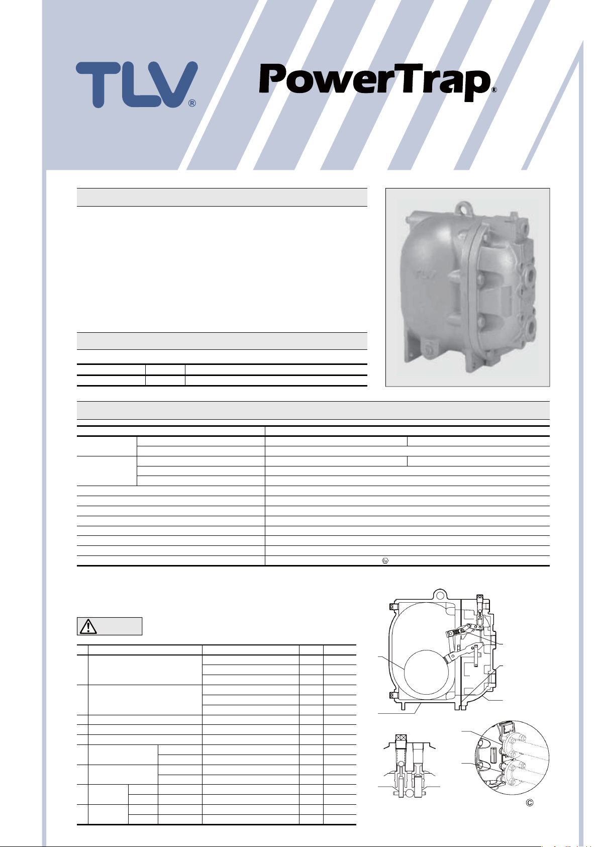
COMPACT MECHANICAL PUMP FOR CONDENSATE REMOVAL AND RECOVERY
Features
Pump for a wide range of applications. Ideal for low flow condensate
removal from vented receivers situated at low levels.
1. Handles high-temperature condensate without cavitation.
2. No electric power or additional level controls required, hence
INTRINSICALLY SAFE.
3. Pump will operate with a low filling head (min. 300 mm).
4. Easy, inline access to internal parts simplifies cleaning and reduces
maintenance costs.
5. High-quality stainless steel internals and hardened working surfaces ensure
reliability.
6. Compact design permits installation in a limited space.
7. Cycle Counter installable as option.
SDS U2404-02
Pressure Equipment Directive (PED)
Classification according to PED 2014/68/EU, fluid group 2
Size Category CE marking
DN 25, DN 40 I With CE marking and Declaration of Conformity
Specifications
Model GP10L
Connection
Size
Maximum Operating Pressure (barg) PMO 10.5
Maximum Operating Temperature (°C) TMO 185
Motive Medium Pressure Range (barg) 0.3 to 10.5
Maximum Allowable Back Pressure 0.5 bar less than motive medium pressure used
Volume of Each Discharge Cycle (litre) approximately 6
Motive Medium
Pumped Medium
Optional Specifications for Hazardous Locations ATEX:
*
For details of flange connection, see picture at bottom right ** Do not use with toxic, flammable or otherwise hazardous fluids. 1 bar = 0.1 MPa
***
Do not use for fluids with specific gravities under 0.85 or over 1, or for toxic, flammable or otherwise hazardous fluids.
PRESSURE SHELL DESIGN CONDITIONS (NOT OPERATING CONDITIONS):
Maximum Allowable Pressure (barg) PMA: 13 (Cast Iron), 21 (Cast Steel), 16 (Cast Stainless Steel)
Maximum Allowable Temperature (°C) TMA: 200 (Cast Iron), 220 (Cast Steel, Cast Stainless Steel)
CAUTION
No. Description Material DIN*ASTM/AISI
Body
q
Cover
w
Cover Gasket Graphite Compound — —
e
Float Stainless Steel SUS316L 1.4404 AISI316L
r
Snap-action Unit Stainless Steel — —
t
Motive Medium
y
Intake Valve Unit
Exhaust Valve
u
Unit
Inlet
i
Check Valve
Outlet
o
Check Valve
*
Equivalent materials ** Not shown
Pumped Medium Inlet & Outlet Screwed and Flanged
Motive Medium & Pump Exhaust Screwed
Pumped Medium: Inlet × Outlet 1”/ DN 25 × 1”/ DN 25 1
Motive Medium Inlet
Pump Exhaust Outlet
**
***
To avoid abnormal operation, accidents or serious injury, DO NOT use
this product outside of the specification range. Local regulations may
restrict the use of this product to below the conditions quoted.
Cast Iron FC250 0.6025 A126 Cl.B
Cast Steel A216 Gr.WCB
Cast Stainless Steel A351 Gr.CF8 1.4312 —
Cast Iron FC250 0.6025 A126 Cl.B
Cast Steel A216 Gr.WCB
Cast Stainless Steel A351 Gr.CF8 1.4312 —
Intake Valve Stainless Steel SUS440C 1.4125 AISI440C
Valve Seat Stainless Steel SUS420F 1.4028 AISI420F
Exhaust Valve Stainless Steel SUS440C 1.4125 AISI440C
Valve Seat Stainless Steel SUS420F 1.4028 AISI420F
**
Screwed CK3MG
Flanged CKF5M Stainless Steel SUS304 1.4301 AISI304
Screwed CK3MG
Flanged CKF3M
Cast Stainless Steel A351 Gr.CF8
**
Cast Stainless Steel A351 Gr.CF8
Cast Stainless Steel A351 Gr.CF8
**
**
1.0619 —
1.0619 —
1.4312 —
1.4312 —
1.4312 —
Saturated Steam, Compressed Air, Nitrogen
*
1
⁄2”
1
⁄2”
Steam Condensate, Water
II2GExhIICT3Gb
*
r
q
i
o
yu
Screwed
1
⁄2” × 1”
t
w
e
Flange Connection (25 mm)
Copyright
TLV
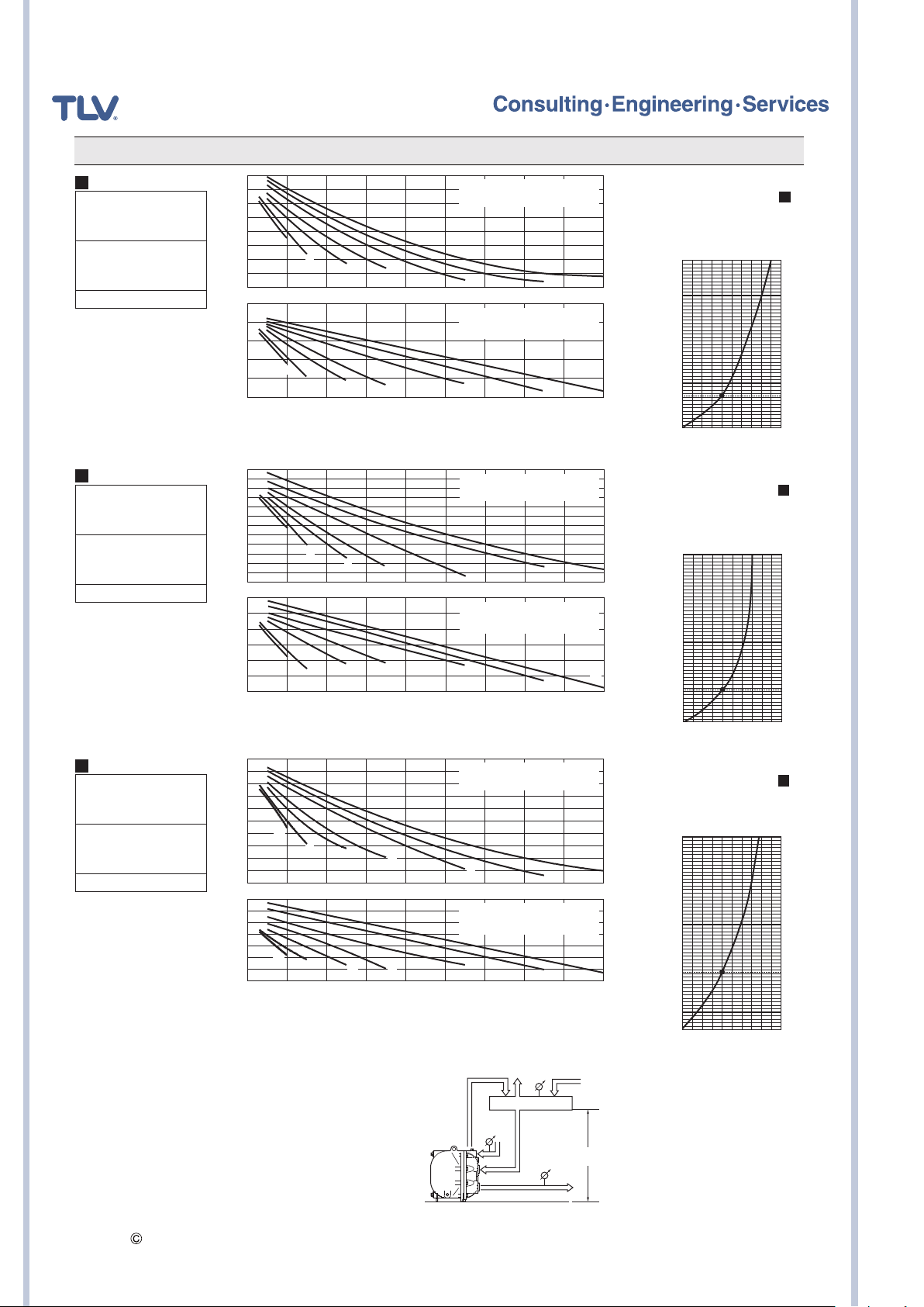
Discharge Capacity
A
Connection: Screwed
Inlet size: 1”
Outlet size: 1”
Check Valve: CK3MG
Inlet: 1”
Outlet: 1”
Filling Head: 630 mm
1200
1000
800
600
400
0123456789
1250
1200
115 0
Discharge Capacity (kg/h)Discharge Capacity (kg/h) Discharge Capacity (kg/h)
110 0
1050
1000
0123456789
Motive Medium: Saturated Steam
Motive Steam Pressure: barg
Condensate Temperature: 90 °C
¡CORRECTION FACTOR
For discharge capacity graph
installed with filling head
A
other than 630 mm
1.5
2
3
4
1.5
2
3
4
6
Motive Medium: Compressed Air
Motive Air Pressure: barg
Condensate Temperature: 20 °C
6
8
8
System Back Pressure (barg) 1 bar = 0.1 MPa
(minimum filling head: 450 mm)
1400
10
10
1300
1200
110 0
(mm)
1000
900
800
700
Filling Head
630
500
450
0.6
1. 0
1. 5
B
Connection: Screwed
Inlet size: 11⁄2”
Outlet size: 1”
Check Valve: CK3MG
Inlet: 1
Outlet: 1”
Filling Head: 630 mm
1
⁄2”
1600
1400
1200
1000
1700
1600
1500
1400
1300
1200
110 0
1.5
800
600
400
0123456789
0123456789
2
3
1.5
3
2
System Back Pressure (barg) 1 bar = 0.1 MPa
C
Connection: Flanged
Inlet size: DN 25
Outlet size: DN 25
Check Valve:
Inlet
(CKF5M)
: DN 25
Outlet
(CKF3M)
: DN 25
Filling Head: 630 mm
1200
110 0
1000
900
800
700
1.5
600
500
400
300
200
0123456789
1250
1200
115 0
110 0
1050
1000
950
900
0123456789
2
3
1.5
2
3
System Back Pressure (barg) 1 bar = 0.1 MPa
NOTE:
¡
A check valve must be installed at both the pumped medium inlet and
outlet. To achieve the above capacities with the standard GP10L
configuration, either TLV check valves CK3MG (inlet & outlet), or
CKF5M (inlet) and CKF3M (outlet) must be used. depending on
connection type.
¡
Motive medium pressure minus back pressure must be greater than
0.5 bar.
¡
In closed system applications, the motive medium must be compatible
with the liquid being pumped. If a non-condensable gas such as air or
nitrogen is used as the motive medium, consult TLV for assistance.
¡
A strainer must be installed at the motive medium and pumped
medium inlets.
Copyright
TLV
Motive Medium: Saturated Steam
Motive Steam Pressure: barg
Condensate Temperature: 90 °C
4
4
4
4
6
Motive Medium: Compressed Air
Motive Air Pressure: barg
Condensate Temperature: 20 °C
6
Motive Medium: Saturated Steam
Motive Steam Pressure: barg
Condensate Temperature: 90 °C
6
Motive Medium: Compressed Air
Motive Air Pressure: barg
Condensate Temperature: 20 °C
6
¡FILLING HEAD AND PRESSURES
Condensate Receiv
Pm
GP10L
¡CORRECTION FACTOR
For discharge capacity graph
with filling head other than 630 mm
(minimum filling head: 450 mm)
8
10
10
8
1400
1300
1200
110 0
(mm)
1000
900
800
700
Filling Head
630
500
450
0.6
1. 0
B
1. 5
¡CORRECTION FACTOR
For discharge capacity graph
with filling head other than 630 mm
(minimum filling head: 300 mm)
1400
1300
10
8
8
10
P
1
er
The discharge capacity is determined by
the motive
pressure (Pm) and back pressure (P
1200
110 0
(mm)
1000
900
800
700
630
Filling Head
500
400
300
0.6
1. 0
medium, motive medium
Make sure that:
Discharge Capacity
Filling
Head
P
2
Correction Factor
×
>
Required Flow Rate
C
1. 5
2).
SDS U2404-02

Dimensions
Units: mm
Weight (kg)
Pump Exhaust Outlet
BSP ½
Note: All Plug Holes BSP ½
360 250
16
300
410
375
237
107
16
Motive Medium Inlet
BSP ½
Pumped Medium Inlet
BSP 1/DN 25
PN 10, 16, 25
Pumped Medium Outlet
352
BSP 1/DN 25
PN 10, 16, 25
Cast steel/
*
cast stainless steel only
*
, 40* or BSP 1½
*
, 40
*
Cast Iron
Cast Steel
Cast Stainless Steel
* Approx.
Size of Receiver/Reservoir
The receiver/reservoir must have a capacity sufficient to store the condensate produced during the PowerTrap operation and
discharge. A receiver will generally be larger than a reservoir because it must handle the condensate both as a liquid and as
flash steam, and separate one from the other so that only condensate is sent to the PowerTrap.
45
49
42*
1.Size of Receiver (flash steam is involved)
(Length: 1 m)
Flash steam up to
(
kg/h
)
25 80 25
50 100 50
75 125 50
100 150 80
150 200 80
200 200 100
300 250 125
400 300 125
500 350 150
700 400 200
800 450 200
1000 500 200
1100 500 250
1400 550 250
1500 600 250
Receiver diameter
(mm)
Vent pipe diameter
(mm)
3.If flash steam is condensed before it enters
the receiver/reservoir, compare tables 1and 2
2.Size of Reservoir (flash steam is not involved)
Amount of
condensate
(kg/h)
300 or less 1.2
400 1.5 1.0
500 2.0 1.2 0.5
600 1.5 0.6
800 2.0 0.8 0.5
1000 1.0 0.7
1500 1.5 1.0
2000 2.0 1.3 0.6
3000 2.0 0.9 0.5
4000 1.2 0.7
5000 1.4 0.8 0.5
6000 1.7 1.0 0.6
7000 2.0 1.2 0.7
8000 1.3 0.8
9000 1.5 0.9
10000 1.7 1.0
Reservoir length can be reduced by 50% when the motive medium pressure
(Pm) divided by back pressure (P
and choose the larger of the two sizes.
Steam or Air Consumption (Motive Medium)
10
9
8
6
(kg)
5
4
Steam Consumption
3
2
(per 1 tonne condensate)
1. 7
Steam Consumption
1
12345678910
Air Consumption
Back Pressure (barg) 1 bar = 0.1 MPa
*
Equivalent consumption of air at 20 °C
under atmospheric pressure
7
*
6
)
3
5
(m
Air Consumption
Cycle Counter (option)
Two types of counter can be installed on
the GP10L to monitor the number of
pumping cycles and help to determine the
timing of maintenance, or estimate the
volume of pumped condensate.
C1CM – (Counter Unit
・
Type): Self-contained
standalone unit.Includes an
LCD counter display and an
operation indicator LED
(per 1 tonne condensate)
C1SM – (Terminal Box
・
Type): Designed for use with
remote monitoring equipment
and systems.
See the Cycle Counter SDS for further details.
Reservoir diameter (mm) and length (m)
40 50 80 100 150 200 250
m 0.7
2
) equals 2 or greater (when Pm ÷ P2 ≧ 2).
LED
LCD
C1CM
C1SM
Copyright
TLV
SDS U2404-02

System Package (Open Systems)
Single System Package Type S1L
Discharge Capacity: see discharge capacity graph (no correction factor required, max. capacity 1 t/h)
Maximum Allowable Flash Steam: 100 kg/h Tank Size: 12ℓ Weight: 120 kg
445
Exhaust Outlet DN 50 PN 16
A
φ
165
460
For Level Gauge
300
106
Pumped Medium
Inlet DN 50 PN 16
Motive Medium
Inlet BSP ½
Pumped Medium
Outlet BSP 1
100
660 135 290
approx. 745
approx.
85
930
705
408
163
151
95
520
Single System Package Type S1M
Discharge Capacity: see discharge capacity graph (no correction factor required, max. capacity 1.5 t/h)
Maximum Allowable Flash Steam: 200 kg/h Tank Size: 22ℓWeight: 130 kg
165
Exhaust Outlet DN 80 PN 16
B
151
Pumped Medium
Inlet DN 50
PN 16
460
For Level Gauge
300106
660
approx. 745
Standards:
Flanged connections: DIN 2501
Screwed connections: DIN 2999
Other standards available
Actual specifications may differ from the ones shown. Please consult TLV for details.
Copyright
TLV
Motive Medium
Inlet BSP ½
Pumped Medium
Outlet BSP 1
91
approx.
85
https://www.tlv.com
930
408
163
(O)
705
135 275
520
110
Units: mm
SDS U2404-02 Rev. 2/2021
Products for intended use only.
Specifications subject to change without notice.
 Loading...