

TLV COS Series, COSR Series, COS-3, COSR-3, COS-21 Instruction Manual
...
Copyright (C) 2018 by TLV CO., LTD. All rights reserved.
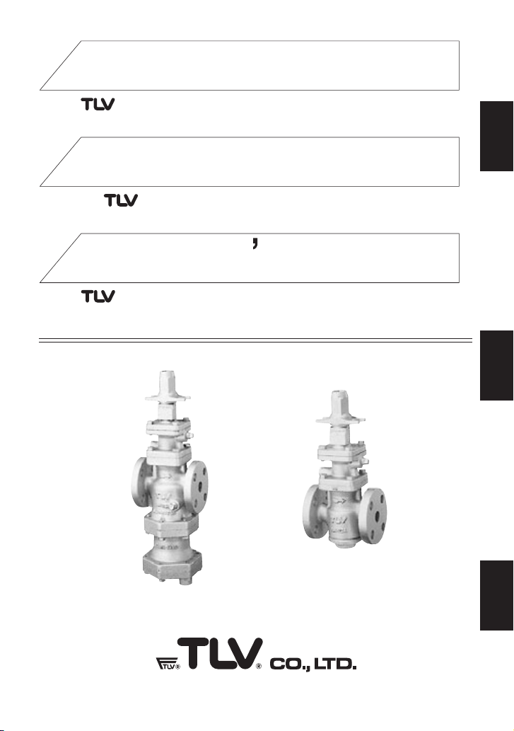
PRESSURE REDUCING VALVES FOR STEAM
DRUCKMINDERVENTILE FÜR DAMPF
COS/COSR Series
COS/COSR Serie
DÉTENDEURS-RÉGULATEURS DE PRESSION POUR VAPEUR
Gamme COS/COSR
COS-3/COS-16
COS-21
COSR-3/COSR-16
COSR-21
INSTRUCTION MANUAL
Keep this manual in a safe place for future reference
EINBAU- UND BETRIEBSANLEITUNG
Gebrauchsanleitung leicht zugänglich aufbewahren
MANUEL D UTILISATION
Conserver ce manuel dans un endroit facile d'accès
Deutsch
Français
English
Introduction
Steam-using equipment can perform its intended operation only when dry saturated steam is
available. Steam containing entrained condensate, scale, air, etc. not only reduces steam
equipment productivity, but also shortens the life of pressure reducing valves.
REDUCING VALVES models COS/COSR are innovative reducing valves, which help
eliminate these problems by supplying dry saturated steam at a constant pressure at all times.
This manual should be read prior to installing or operating COS/COSR SERIES REDUCING
VALVES.
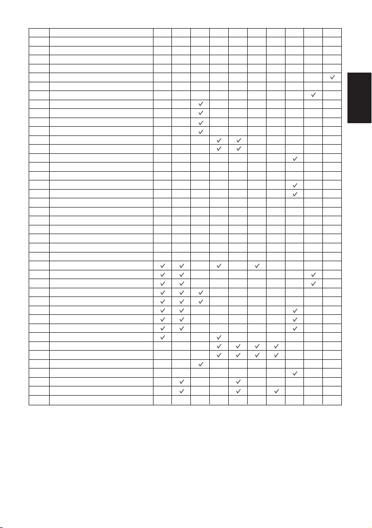
Table of Contents
1
2
3
4
4.1
4.2
4.3
4.4
4.5
4.6
4.7
4.8
4.9
4.10
4.11
4.12
4.13
4.14
4.15
4.16
4.17
5
6
6.1
6.2
6.3
6.4
6.5
6.6
6.7
6.8
6.9
7
8
Safety Considerations
Configuration
COS-3 / COS-16 / COS-21
COSR-3 / COSR-16 / COSR-21
Specifications
Piping and Installation
Recommended Straight Pipe Runs
Installing an ON-OFF Valve
Installing a Control Valve
Blowdown
Remove Protective Seals
Installation Angle
Spacer Installation
Piping Support
Maintenance Space
Trap Outlet Pipe
Blowdown Valve
Accessories
Piping Size / Diffuser
Two-stage Pressure Reduction
Strainer Installation
External Sensing Line
Internal Sensing for North
American Models
Adjustment
Disassembly and Inspection
Before Disassembly
Disassembling the Adjustment Section
Disassembling the Pilot Section
Disassembling the Piston
Disassembling the Separator
and Main Valve
Disassembling the Steam Trap
Cleaning
Reassembly
Regular Inspection and
Maintenance
Troubleshooting
Product Warranty
2
3
3
5
7
8
8
9
9
9
9
9
9
10
10
10
10
11
11
11
11
12
13
14
15
16
16
16
18
19
20
20
21
22
23
24
Page PageSection Section
English
1
1. Safety Considerations
• Read this section carefully before use and be sure to follow the instructions.
• Installation, inspection, maintenance, repairs, disassembly, adjustment and valve
opening/closing should be carried out only by trained maintenance personnel.
• The precautions listed in this manual are designed to ensure safety and prevent equipment
damage and personal injury. For situations that may occur as a result of erroneous handling,
three different types of cautionary items are used to indicate the degree of urgency and the
scale of potential damage and danger: DANGER, WARNING and CAUTION.
• The three types of cautionary items above are very important for safety; be sure to observe
all of them, as they relate to installation, use, maintenance, and repair. Furthermore, TLV
accepts no responsibility for any accidents or damage occurring as a result of failure to
observe these precautions.
Indicates an urgent situation
which poses a threat of
death or serious injury.
Indicates that there is a
potential threat of death
or serious injury.
WARNING
CAUTION
WARNING
DANGER CAUTION
Indicates that there is a
possibility of injury or equipment/product damage.
NEVER apply direct heat to the float. The float may explode due to
increased internal pressure, causing accidents leading to serious injury
or damage to property and equipment.
Install properly and DO NOT use this product outside the
recommended operating pressure, temperature and other
specification ranges. Improper use may result in such hazards as
damage to the product or malfunctions, which may lead to serious
accidents. Local regulations may restrict the use of this product to below
the conditions quoted.
Take measures to prevent people from coming into direct contact
with product outlets. Failure to do so may result in burns or other injury
from the discharge of fluids.
Use hoisting equipment for heavy objects (weighing approximately
20 kg (44 lb) or more). Failure to do so may result in back strain or other
injury if the object should fall.
DO NOT use this product in excess of the maximum operating
pressure differential. Such use could make discharge impossible.
When disassembling or removing the product, wait until the internal
pressure equals atmospheric pressure and the surface of the
product has cooled to room temperature. Disassembling or removing
the product when it is hot or under pressure may lead to discharge of
fluids, causing burns, other injuries or damage.
Be sure to use only the recommended components when repairing
the product, and NEVER attempt to modify the product in any way.
Failure to observe these precautions may result in damage to the product
or burns or other injury due to malfunction or the discharge of fluids.
Use only under conditions in which no freeze-up will occur. Freezing
may damage the product, leading to fluid discharge, which may cause
burns or other injury.
Use under conditions in which no water hammer will occur. The
impact of water hammer may damage the product, leading to fluid
discharge, which may cause burns or other injury.
Do not use excessive force when connecting threaded pipes to the
product. Overtightening may cause breakage leading to fluid discharge,
which may cause burns or other injury.
English
2
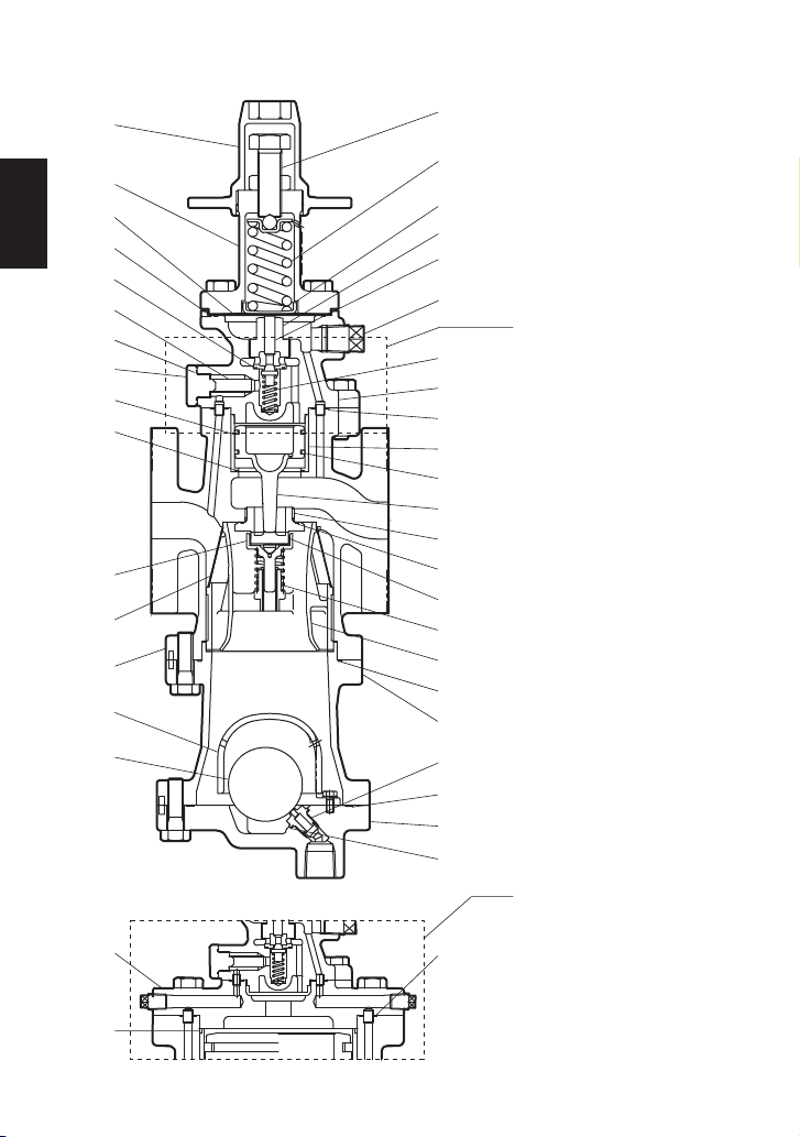
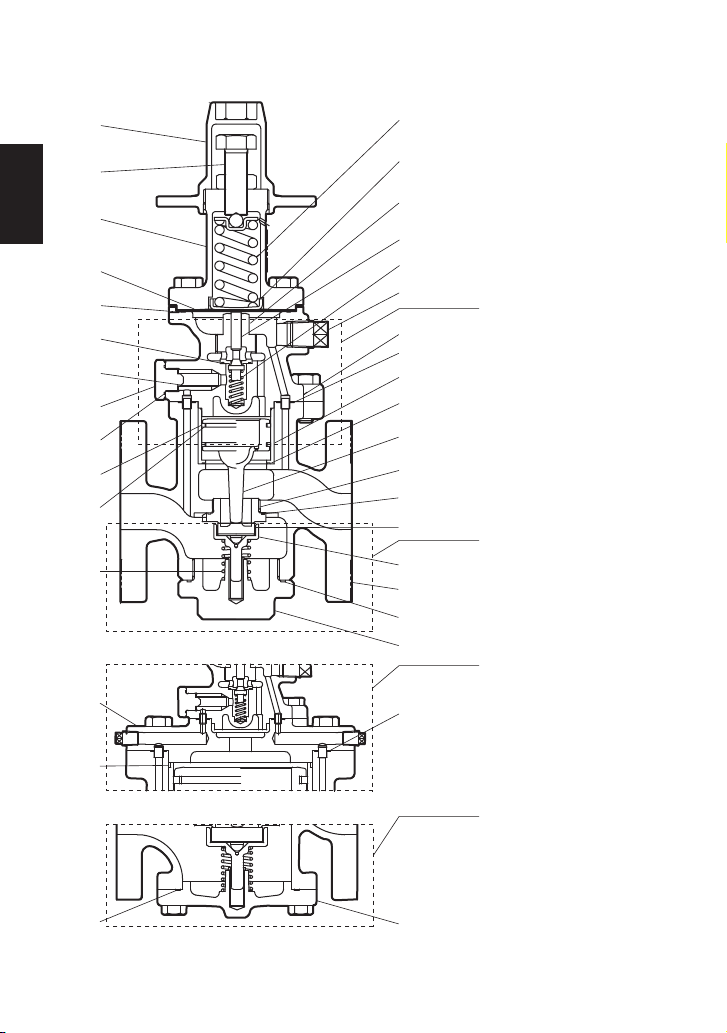
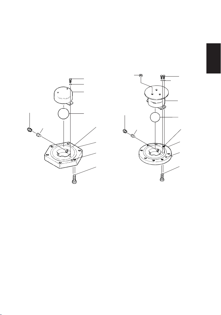
COS-3 / COS-16 / COS-21
2. Configuration
@4
@1
$1
!9
#3
#2
!4
#1
!5
#6
#4
@3
@2
@0
!8
!7
@5
#8
!6
@6
!3
#5
!2
o
#0
!0
#7
r
@9
w
u
@8
e
@7
$0
#9
q
i
t
y
!1
Pilot Section
COS-3
20 – 50 mm ( " – 2")
COS-16
15 – 50 mm ( " – 2")
COS-21
15 – 50 mm ( " – 2")
Pilot Section
COS-16
65 – 100 mm (2 " – 4")
COS-21
65 – 100 mm (2 " – 4")
2
1
/
4
3
/
2
1
/
2
1
/
2
1
/
English
3
Description
Main Body
Trap Body
Trap Cover
Separator
Float
Float Cover
Trap Valve Seat
Separator Screen
Main Valve Seat
Main Valve
Main Valve Holder
Piston
Cylinder
Pilot Screen
Pilot Screen Holder
Pilot Body
Pilot Valve
Pilot Valve Seat
Diaphragm
Diaphragm Support
Spring Housing
Coil Spring
Adjustment Screw
Spanner Cap
Plug – Sensing Line Port
Lower Pilot Body Gasket
Trap Valve Seat Gasket
Trap Cover Gasket
Trap Body Gasket
Main Valve Seat Gasket
Pilot Screen Holder Gasket
Pilot Valve Seat Gasket
Upper Pilot Body Gasket
Cylinder Gasket
Piston Ring
Tension Ring
Main Valve Spring
Pilot Valve Spring
Seal Ring
Pilot Cover Gasket
Pilot Cover
A1 A2 B C1 C2 D1 D2 E F G
No.
1
2
3
4
5
6
7
8
9
10
11
12
13
14
15
16
17
18
19
20
21
22
23
24
25
26
27
28
29
30
31
32
33
34
35
36
37
38
39
40
41
* Replacement parts available for COS-3/COS-16 in kits specified; contact TLV for COS-21 parts
Maintenance kit for COS-3 (20 – 50 mm, " – 2") and COS-16 (15 – 50 mm, " – 2")
Maintenance kit for COS-16 (65 – 100 mm, 2 " – 4")
Repair kit for Main Valve
Repair kit for Piston for COS-3 (20 – 50 mm, " – 2") and COS-16 (15 – 50 mm, " – 2")
Repair kit for Piston for COS-16 (65 – 100 mm, 2 " – 4")
Repair kit for Piston Ring for COS-3 (20 – 50 mm, " – 2") and COS-16 (15 – 50 mm, " – 2")
Repair kit for Piston Ring for COS-16 (65 – 100 mm, 2 " – 4")
Repair kit for Pilot Valve
Repair kit for Trap Valve Seat
Float
(A1)
(A2)
(B)
(C1)
(C2)
(D1)
(D2)
(E)
(F)
(G)
2
1
/
4
3
/
4
3
/
2
1
/
2
1
/
4
3
/
2
1
/
2
1
/
2
1
/
English
4
Cover Plug
COSR-3
20, 25 mm ( " , 1")
COSR-16
15 – 25 mm ( " – 1")
2
1
/
4
3
/
Pilot Section
COSR-3
20 – 50 mm ( " – 2")
COSR-16
15 – 50 mm ( " – 2")
COSR-21
15 – 50 mm ( " – 2")
2
1
/
4
3
/
2
1
/
Pilot Section
COSR-16
65 – 150 mm (2 " – 6")
COSR-21
65 – 100 mm (2 " – 4")
2
1
/
2
1
/
Cover
COSR-3
32 – 50 mm (1 " – 2")
COSR-16
32 – 150 mm (1 " – 6")
COSR-21*
15 – 100 mm ( " – 4")
4
1
/
4
1
/
2
1
/
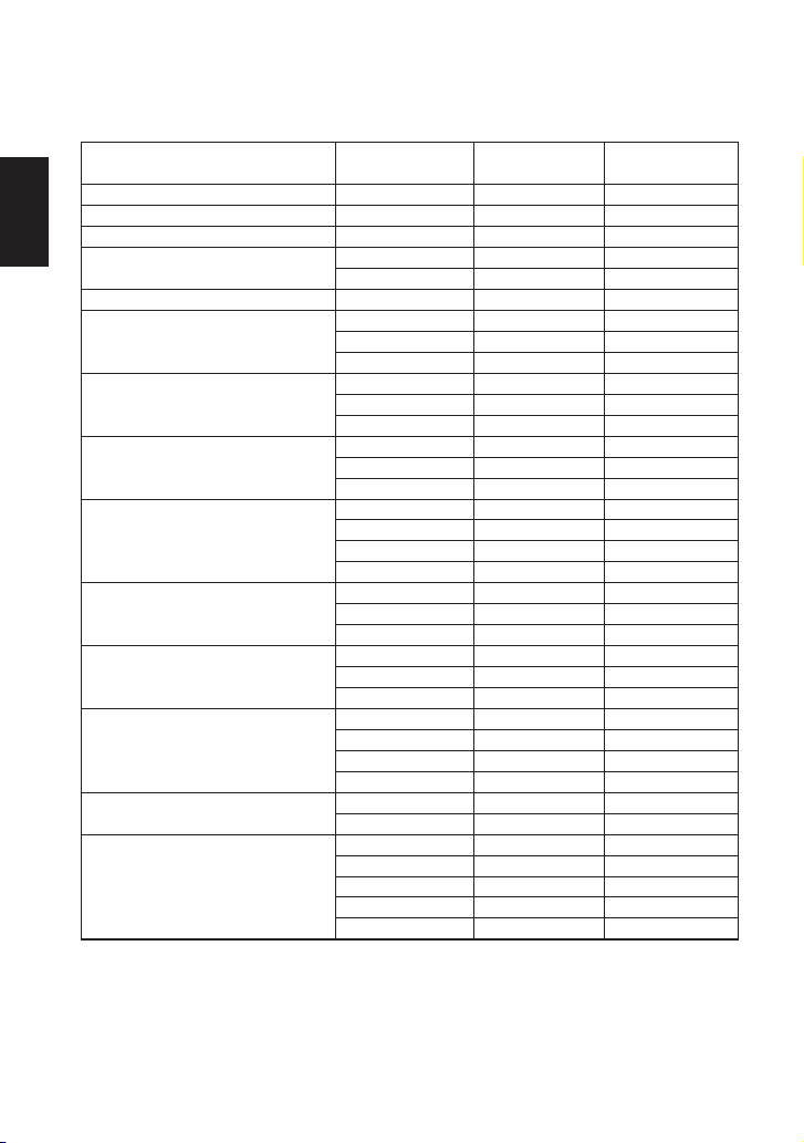
COSR-3 / COSR-16 / COSR-21
@3
!8
!7
@5
!6
!3
!2
@9
@1
@8
@7
@4
#1
!1
@0
@6
o
@2
!0
@1
w
w
#0
#3
r
u
e
q
t
y
!9
#2
!4
!5
i
*Cover configuration differs slightly for models with connections other than DIN PN flange.
English
5
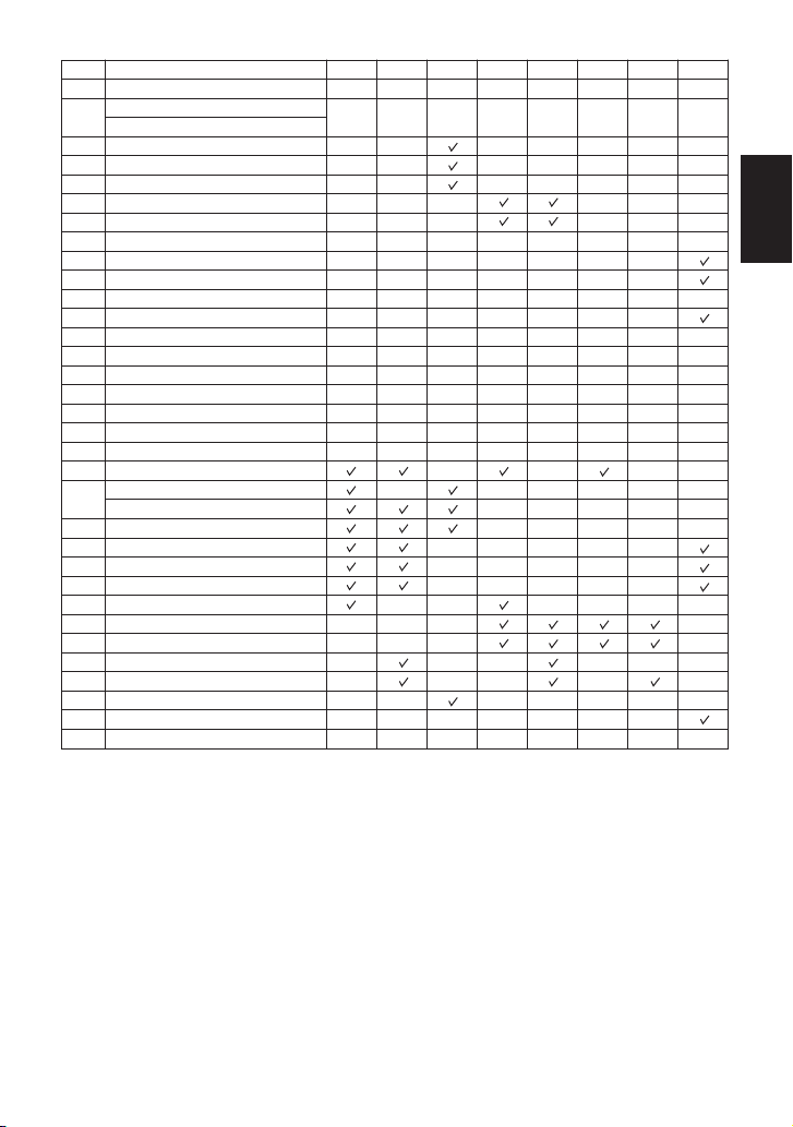
Description
Main Body
Cover Plug
Cover
Main Valve Seat
Main Valve
Main Valve Holder
Piston
Cylinder
Pilot Body
Pilot Valve
Pilot Valve Seat
Diaphragm
Pilot Screen
Pilot Screen Holder
Diaphragm Support
Coil Spring
Spring Housing
Adjustment Screw
Spanner Cap
Plug – Sensing Line Port
Lower Pilot Body Gasket
Cover Plug Gasket
Cover Gasket
Main Valve Seat Gasket
Pilot Screen Holder Gasket
Pilot Valve Seat Gasket
Upper Pilot Body Gasket
Cylinder Gasket
Piston Ring
Tension Ring
Seal Ring
Pilot Cover Gasket
Main Valve Spring
Pilot Valve Spring
Pilot Cover
A1 A2 B C1 C2 D1 D2 E
No.
1
2
3
4
5
6
7
8
9
10
11
12
13
14
15
16
17
18
19
20
21
22
23
24
25
26
27
28
29
30
31
32
33
* Replacement parts available for COSR-3/COSR-16 in kits specified; contact TLV for COSR-21 parts
Maintenance kit for COSR-3 (20 – 50 mm, " – 2") and COSR-16 (15 – 50 mm, " – 2")
Maintenance kit for COSR-16 (65 – 150 mm, 2 " – 6")
Repair kit for Main Valve
Repair kit for Piston for COSR-3 (20 – 50 mm, " – 2") and COSR-16 (15 – 50 mm, " – 2")
Repair kit for Piston for COSR-16 (65 – 150 mm, 2 " – 6")
Repair kit for Piston Ring for COSR-3 (20 – 50 mm, " – 2") and COSR-16 (15 – 50 mm, " – 2")
Repair kit for Piston Ring for COSR-16 (65 – 150 mm, 2 " – 6")
Repair kit for Pilot Valve
(A1)
(A2)
(B)
(C1)
(C2)
(D1)
(D2)
(E)
2
1
/
4
3
/
4
3
/
2
1
/
2
1
/
4
3
/
2
1
/
2
1
/
2
1
/
English
6
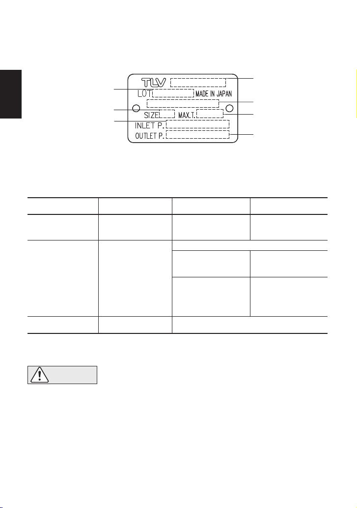
3. Specifications
To avoid malfunctions, product damage, accidents or serious injury,
install properly and DO NOT use this product outside the specification
range. Local regulations may restrict the use of this product to below the
conditions quoted.
CAUTION
Refer to the product nameplate for detailed specifications.
* Valve No. is displayed for products with options. This item is omitted from the nameplate when
there are no options.
Acceptable Operating Range
COS-21
COSR-21
5% of rated flow rate;
10% of rated flow rate for sizes 65 mm and larger
Minimum Adjustable
Flow Rate
1.35 – 2.1 MPaG
13.5 – 21 barg
190 – 300 psig
Minimum adjustable
pressure of 0.55 MPaG,
5.5 barg, 80 psig
Maximum pressure
differential of
0.85 MPa
8.5 bar
120 psig
COS-16
COSR-16
0.2 – 1.6 MPaG
2 – 16 barg
30 – 250 psig
COS-3
COSR-3
Model
1 MPa = 10 bar = 10.197 kg/cm
2
Primary Pressure
Range
0.1 – 0.3 MPaG
1 – 3 barg
15 – 45 psig
0.01 – 0.05 MPaG
0.1 – 0.5 barg
1.5 – 7 psig
Secondary Pressure
Adjustable Range
(All conditions
must be met)
5% of rated flow rate
Minimum adjustable
pressure of 0.03 MPaG,
0.3 barg, 5 psig
Pressure differential
between
0.07 – 0.85 MPaG
0.7 – 8.5 barg
10 – 120 psig
Within 10 – 84% of primary pressure
Model
Valve No.*
Maximum Operating
Temperature
Secondary Pressure
Adjustable Range
Production Lot No.
Nominal Diameter
Primary Pressure Range
English
7
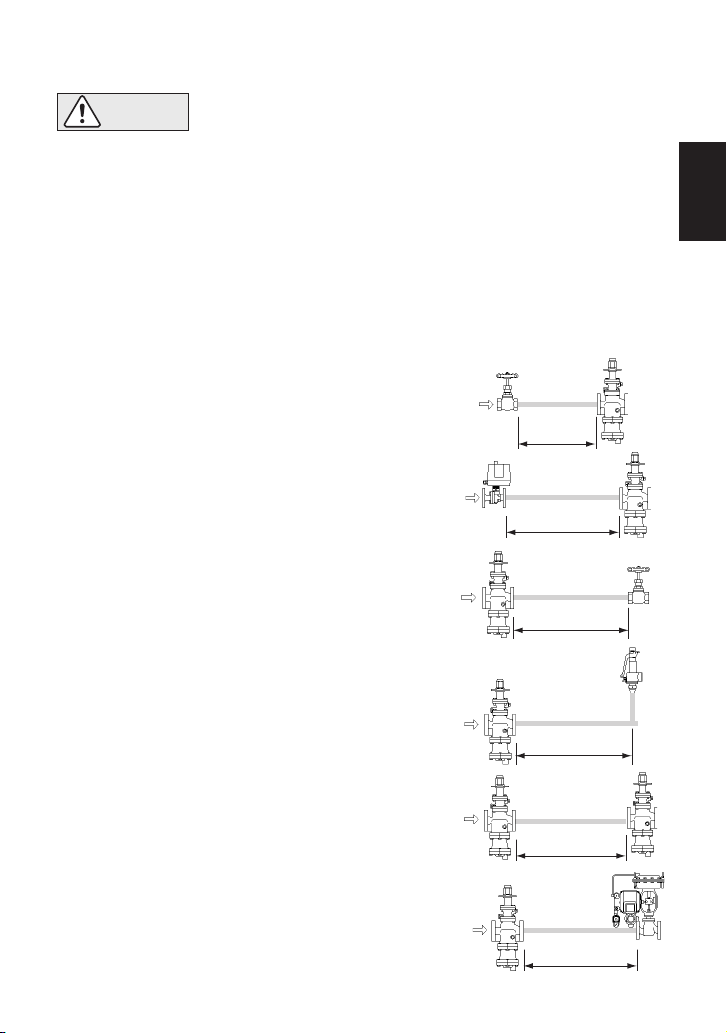
30 d or more
30 d or more
If the COS/COSR is installed either directly before or after an elbow or control valve,
unevenness in flow may result in chattering and unstable pressure.
To ensure stable steam flow, it is recommended that the COS/COSR be installed on straight
runs of piping, as illustrated below.
4.1 Recommended Straight Pipe Runs
4. Piping and Installation
q Inlet (primary side) of the COS/COSR
• Installation, inspection, maintenance, repairs, disassembly, adjustment
and valve opening/closing should be carried out only by trained
maintenance personnel.
• Take measures to prevent people from coming into direct contact with
product outlets.
• Install for use under conditions in which no freeze-up will occur.
• Install for use under conditions in which no water hammer will occur.
• Maintain a straight piping run of 10 d or more when a
manual valve, a strainer or an elbow, etc. is installed.
(Example: if nominal size is 25 mm (1"), have 250 mm
(10") or more)
• Maintain a straight piping run of 30 d or more when
an automated valve (on-off valve) is installed.
(Example: If nominal size is 25 mm (1"), have 750 mm
(30") or more)
w Outlet (secondary side) of the COS/COSR
• Maintain a straight piping run of 15 d or more when a
manual valve, a strainer or an elbow, etc. is installed.
(Example: If nominal size is 25 mm (1"), have 375 mm
(15") or more)
• Maintain a straight piping run of 30 d or more when a
safety valve is installed.
(Example: If nominal size is 25 mm (1"), have 750 mm
(30") or more)
• Maintain a straight piping run of 30 d or more when
another pressure reducing valve is installed. (Two-
stage pressure reduction)
(Example: If nominal size is 25 mm (1"), have 750 mm
(30") or more)
• Maintain a straight piping run of 30 d or more when a
control valve or an automated valve (on-off valve) is
installed.
(Example: If nominal size is 25 mm (1"), have 750 mm
(30") or more)
CAUTION
d = pipe diameter
10 d or more
30 d or more
30 d or more
15 d or more
English
8
4.2
Installing an ON-OFF Valve (solenoid valve or motorized valve)
If an on-off valve is required to stop supply of steam to the steam-using equipment, install it at
the inlet side of the COS/COSR (see section 4.1). If a solenoid valve is installed at the outlet of
the COS/COSR, it will cause heavy chattering and may lead to damage of the piston and main
valve. (When the on-off valve opens, the secondary pressure of the COS/COSR changes from
zero to the set pressure. Passing through an area of the reducing ratio of less than 10:1 where
adjustment is impossible, chattering occurs momentarily.)
To save energy, install the on-off valve as near to the boiler as possible.
To prevent water hammer, it is recommended that a slow-acting motorized on-off valve be
used. If a fast-acting solenoid valve is used, the potential water hammer effect can damage the
steam-using equipment and the COS/COSR.
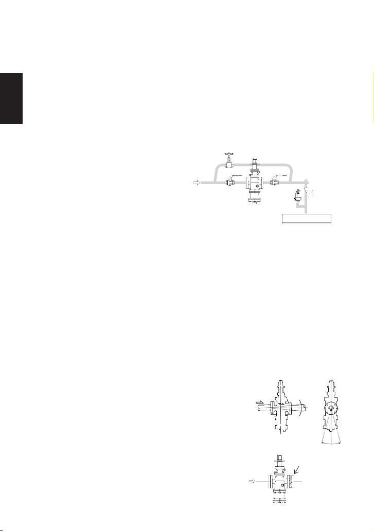
4.3
Installing a Control Valve
A control valve (i.e. for temperature control)
installed between the COS/COSR and the
steam equipment (downstream of the
COS/COSR) may raise pressure between the
COS/COSR and the control valve when the
control valve is closed, depending on their
spatial relationship. Therefore, the control
valve should be installed close to the steamusing equipment. Also, a safety valve should
be installed downstream of the control valve.
NOTE: When installing a safety valve to protect steam-using equipment, be sure to install it on
the equipment or directly before the inlet of the steam-using equipment. If the safety
valve is installed between the COS/COSR and a control valve, an eventual pressure
rise could activate the safety valve
4.4
Blowdown
Before installing the COS/COSR unit, be sure to blow down all piping thoroughly. If this is not
possible, perform a blowdown using the bypass valve. Blowdown is especially important for
newly installed piping or after the system has been shut down for a long period of time.
4.5 Remove Protective Seals
Before installation, be sure to remove all protective seals and caps covering the product inlet
and outlets. (Found at 3 locations for the COS, 2 locations for the COSR.)
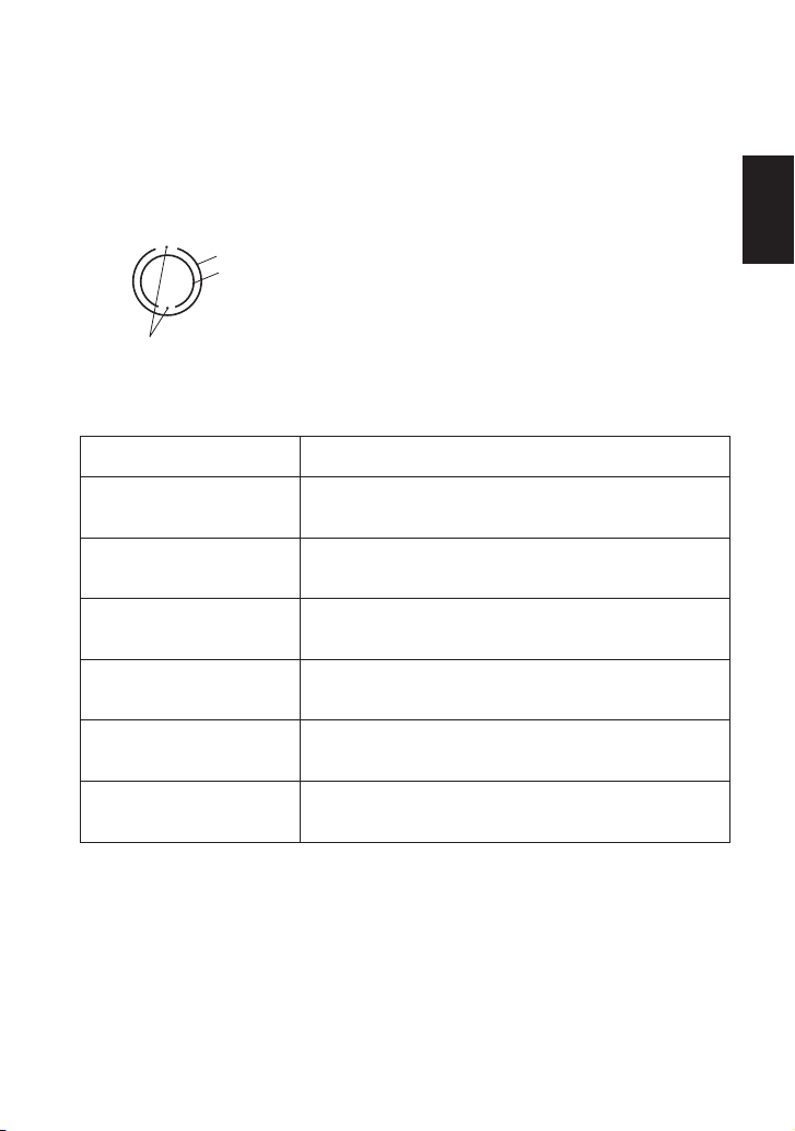
4.6 Installation Angle
Make sure the COS/COSR is installed on horizontal piping, so
that the arrow mark on the body matches the direction of steam
flow and the adjustment screw section faces up. Allowable
inclination is 10 degrees in the fore-aft direction and 15 degrees in
the plane perpendicular to the steam flow line.
4.7 Spacer Installation
If spacing adjustment is necessary to accommodate installation,
install a spacer on the outlet flange. The spacer should consist of
a spacer, gaskets, bolts and nuts. Fit gaskets to both sides of the
spacer between the COS/COSR outlet and the pipe flange.
Fasten with bolts and nuts.
Safety
Valve
COS/COSR
Equipment
Control
Valve
10˚
10˚
15˚ 15˚
Correct Spacer
Location
English
9
Units: mm (inch)
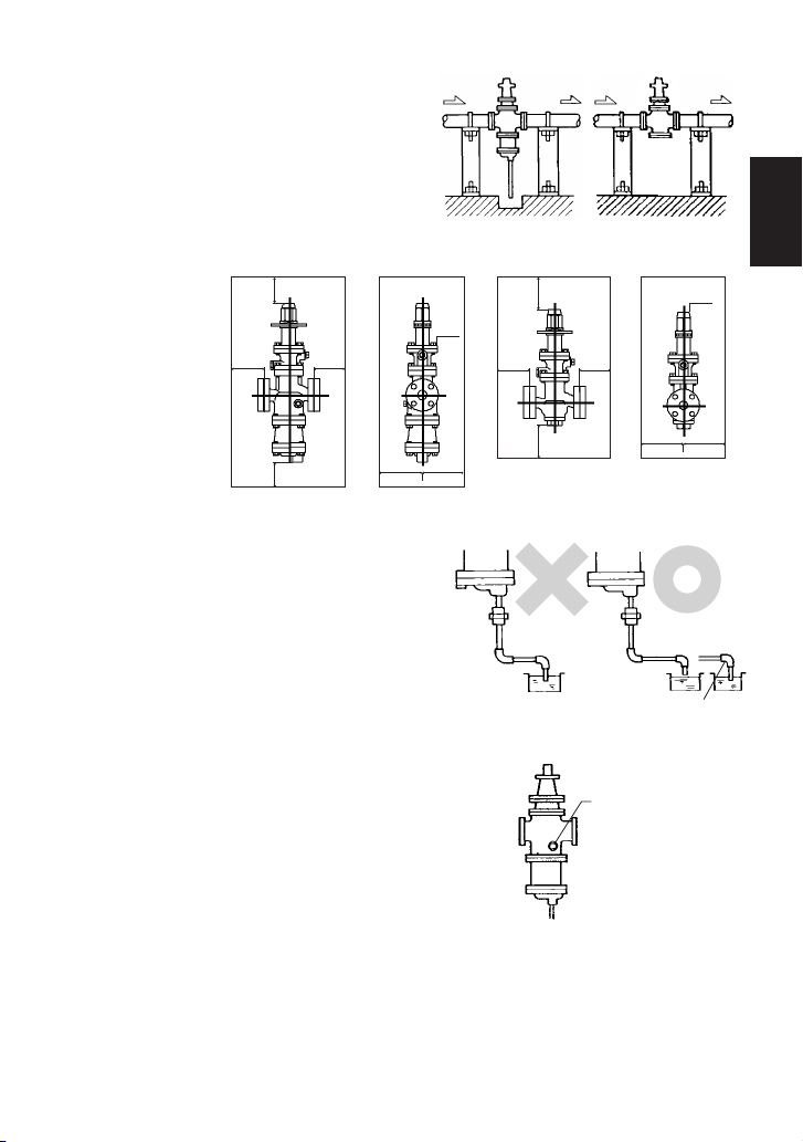
Install the COS/COSR, paying attention to avoid
excessive load, bending or vibration.
Support the inlet and outlet pipes securely.
4.8 Piping Support
Leave sufficient
space for
maintenance,
inspection and
repair.
4.9 Maintenance Space
For ease of maintenance, installation of a union
connection is recommended for the trap outlet pipe.
Connect the outlet pipe to a condensate return line,
or extend it to a trench. In the case of the latter,
make sure the end of the pipe is above the
waterline. (Dirt and water may be sucked up by the
vacuum formed during trap closure and system
shutdown.)
4.10 Trap Outlet Pipe (COS)
In an environment of heavy dirt or scale, or when the steam
equipment is used only periodically, such as for room heating
equipment, be sure to use a blowdown valve.
1. Remove the plug from the main body.
2. Install the blowdown valve.
3. Open the blowdown valve and blow any residual
dirt and scale off of the separator screen.
4. Periodically activate the blowdown valve to keep the
system free of dirt and scale.
4.11 Blowdown Valve (COS) (requires optional plug)
Incorrect Correct
Remove the
optional 10 mm ( ")
plug and install the
blowdown valve
8
3
/
100
(4)
100
(4)
400
(16)
400
(16)
~
300
(-12)
100 (4)
100 (4)
100 (4)
100
(4)
100 (4)
100
(4)
400
(16)
400
(16)
~
300
(~12)
COS COSR
Small Hole
English
10
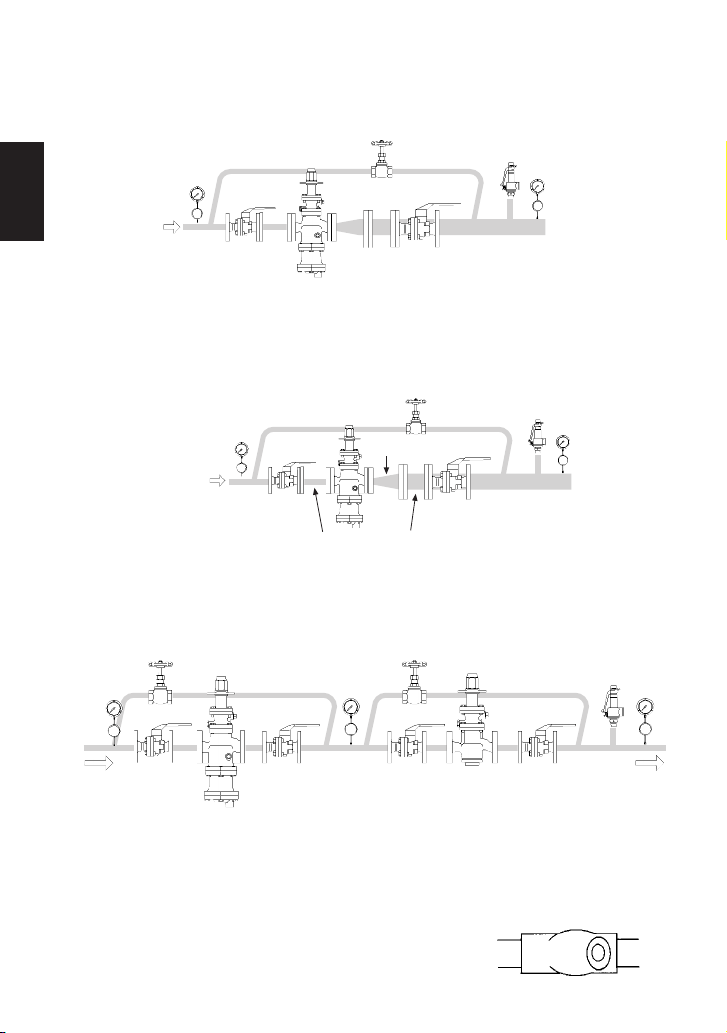
4.12 Accessories
Always install a shutoff valve and pressure gauge at both the inlet and outlet, and a shutoff valve
in the bypass line. Ball valves, which will not retain condensate, are recommended for inlet and
outlet shutoff valves. The bypass pipe should be at least one half the size of the inlet pipe.
4.13 Piping Size / Diffuser
If the secondary steam flow velocity is expected to be more than 30 m/s (100 ft/s), install a
diffuser in order to keep the flow velocity below 30 m/s (100 ft/s). If the distance between the
reducing valve and the steam-using equipment is great, a possible drop in pressure should be
taken into consideration when selecting the piping size.
4.14 Two-stage Pressure Reduction
Two-stage pressure reduction should be performed whenever the pressure cannot be reduced
to the desired level with a single COS/COSR due to operating range limitations, such as when
the reduction ratio is greater than 10:1.
Globe Valve
Diffuser
Pressure
Gauge
Inlet
Bypass Valve
COS/COSR
Shutoff
Valve
Shutoff
Valve
Pressure
Gauge
Bypass Valve
Shutoff
Valve
COSR
Shutoff
Valve
Outlet
Safety Valve
(Relief Valve)
Pressure
Gauge
Straight piping: 10 d or longer upstream 15 d or longer downstream
Pressure
Gauge
Ball Valve
COS/COSR
Ball Valve
Pressure
Gauge
Safety Valve
(Relief Valve)
A strainer should be installed ahead of the COSR. The strainer should be 60 mesh or finer,
but not so fine that it causes constriction of the flow area and a subsequent pressure drop.
The strainer should be installed horizontally and at 90° to its normal orientation to the pipeline,
in order to prevent condensate accumulation in the screen body (see picture).
4.15 Strainer Installation (COSR)
English
11
4.16 External Sensing Line
NORTH AMERICAN MODELS
North American models are factory prepared for external sensing.
An external sensing line MUST be installed.
DO NOT SUPPLY STEAM until all piping and a 10 mm ( ") secondary pressure sensing line
with a slightly falling pitch have been properly installed. Install a shutoff valve in the pressure
sensing line for maintenance purposes.
CAUTION
Keep the shutoff valve in the pressure sensing line open at all times
during operation. If the shutoff valve is closed, COS/COSR will fully open
and PRIMARY PRESSURE WILL BE SUPPLIED TO THE EQUIPMENT
(see 4.16 number 5).
2. Install the blind pin (B) provided by first removing the connecting tube (C) from the main
body or pilot cover and then substituting the pin.
Rc(PT)
NPT (stamped N)
BSP (stamped B)
Connecting tube
15 - 50 mm
( " - 2")
Blind pin
65 - 150 mm
(2 " - 6")
○
D
○
A
○
B
,○
C
○
B
,○
C
○
D
○
A
○B,○
C
2
1
/
2
1
/
1. Loosen and remove the four (4) bolts (A) that attach the pilot body to the main body (15 - 50
mm, "- 2") or the pilot cover (65 - 150 mm, 2 "- 6"), and remove the pilot body.
2
1
/
2
1
/
8
3
/
OTHER MODELS
Other models are factory prepared for internal sensing.
A secondary pressure detection port has been added to all COS/COSR pilot bodies to allow
for installation of a 10 mm ( ") secondary pressure sensing line, which improves performance
and increases valve capacity (flow rate). All except North American models are delivered with a
secondary pressure sensing line plug installed in this port.
When the external detection method is used, follow the installation procedure shown below:
(for North American models, the blind pin has been factory installed and no secondary
pressure sensing line plug is provided).
8
3
/
8
3
/
8
3
/
8
3
/
English
12
8
3
/
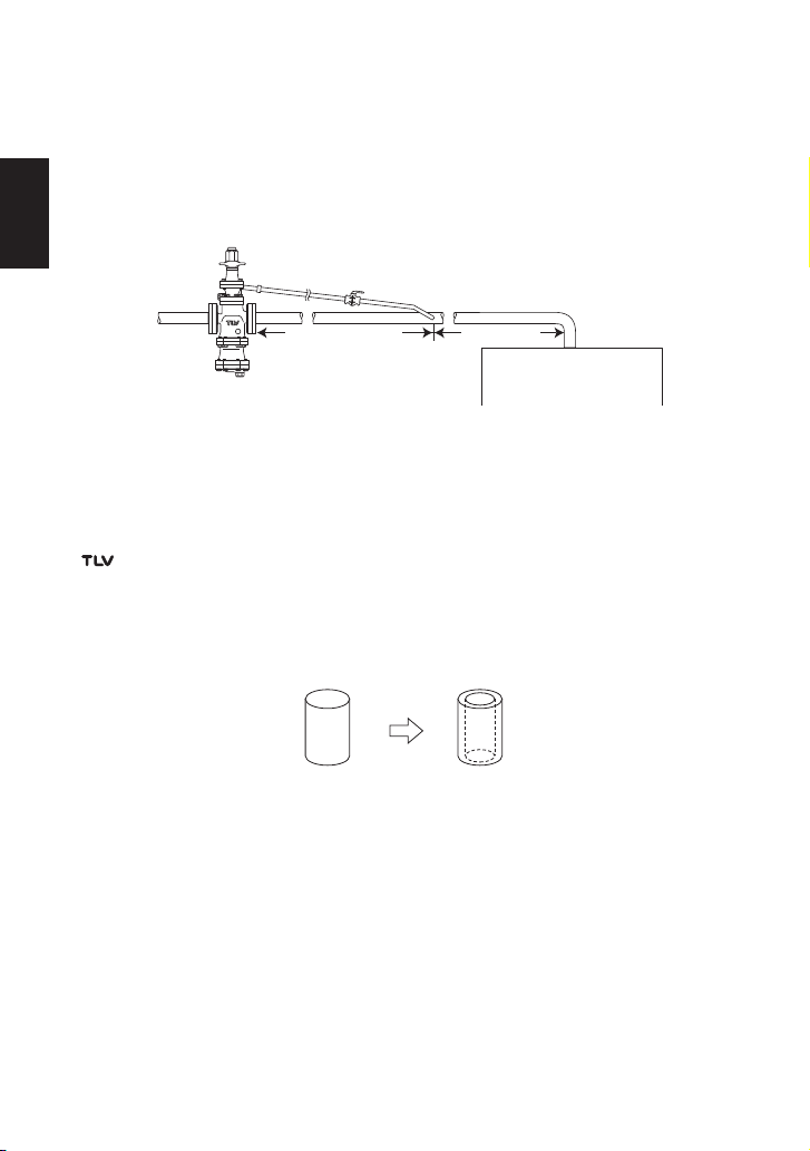
5. Install the secondary pressure sensing line with a slightly falling pitch.
The 10 mm ( ") pipe should be connected to a point where the pressure is to be sensed.
The connection must be at a point on the main piping where there is a straight section of
upstream main piping of a length of 15 d (d = pipe diameter), or 1 m (3'4"), whichever is
greater, and a straight section of downstream main piping of a length of at least 15 d.
1. Loosen and remove the four (4) bolts that attach the pilot body to the main body (15 - 50
mm, "- 2") or the pilot cover (65 - 150 mm, 2 " - 6"), and remove the pilot valve body.
2. Install the connecting tube by first removing the blind pin from the secondary side of the
main body or pilot cover and then substituting the connecting tube.
3. Re-install the pilot body and fasten the four (4) bolts evenly.
Consult page 21 in this manual for torque requirements of these bolts.
4. If a secondary pressure sensing pipe has previously been installed, remove it and be certain
to install the threaded secondary pressure sensing line plug in its place.
A shutoff valve and pipe union should be installed in the secondary pressure sensing line, to be
used when the valve is taken out of service (see beginning of section 4.16).
4.17 Internal Sensing for North American Models
All models except North American models are factory prepared for internal sensing. When
internal pressure sensing is required for North American models, please contact the nearest
representative to request both a connecting tube, which must be installed in place of the
blind pin, and a threaded secondary pressure sensing plug.* Follow the connecting tube
installation procedure shown below:
* Internal sensing should not be used when 15 mm ( ") and 20 mm ( ") COS-16/COSR-16
will be used below 0.3 MPaG (3 barg, 45 psig) and 0.1 MPaG (1 barg, 15 psig) respectively,
and below 50% of primary pressure.
Union
Valve
Connecting tubeBlind pin
15 d or 1 m (3'4"),
whichever is larger
At least 15 d
d = pipe diameter
Steam-using
Equipment
3. Re-install the pilot body and fasten the four (4) bolts (A) evenly to the fastening torque
shown on page 21.
4. Next, loosen and remove the threaded secondary pressure sensing line plug (D) to install the
external pressure sensing line.
2
1
/
2
1
/
4
3
/
2
1
/
English
13
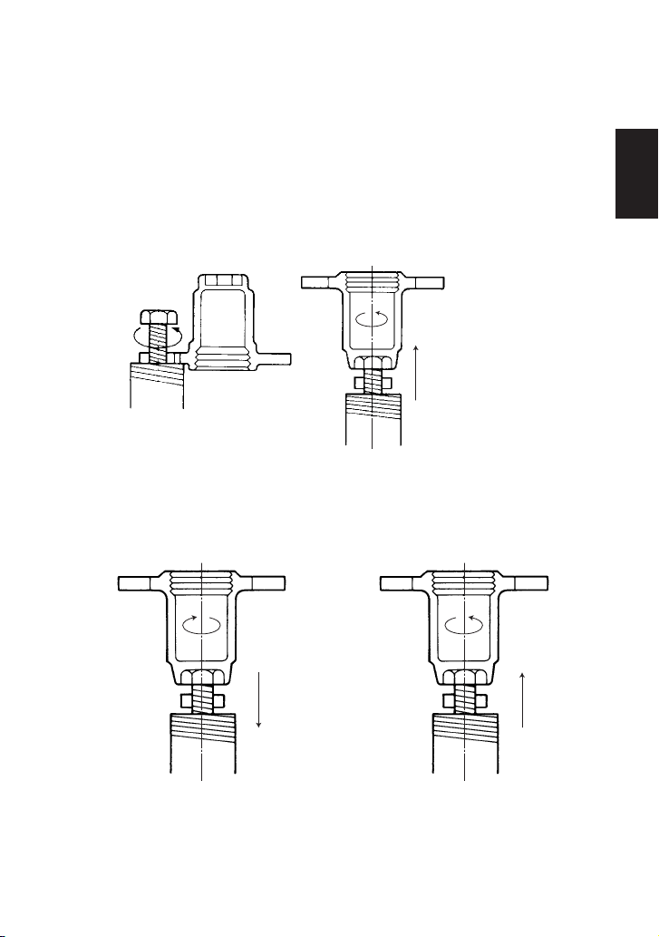
Loosen the Locknut
Loosen the Adjustment Screw
Counterclockwise
Loosen the Adjustment Screw
Decrease Pressure
5. Adjustment
The COS/COSR reducing valve should be properly adjusted for protection of the steam equipment
against water hammer.
1. It is necessary to blow down all pipe lines thoroughly. The blowdown is especially important
if the line is new or has been shut down for a long period of time. Take particular care to
ensure that matter such as condensate and dirt does not remain inside the steam
equipment.
(Stay clear of any pressurized blow-out from the safety valve.)
2. Make sure that the shutoff valve and the bypass valve located upstream and downstream of
the
COS/COSR
are completely closed.
3. Remove the spanner cap, loosen the locknut and turn the adjustment screw
counterclockwise to reduce tension on the coil spring.
7. Slowly, fully open the shutoff valve on the outlet side.
8. After setup, tighten the locknut and replace the spanner cap.
9. When shutting down the system, always close the outlet shutoff valve first and then the inlet
valve.
Counterclockwise
Tighten the Adjustment Screw
Increase Pressure
Clockwise
4. Slowly, fully open the shutoff valve at the inlet of the
COS/COSR
. Allow sufficient time for
condensate remaining at the inlet of the
COS/COSR
to be discharged.
5. Slightly open the shutoff valve at the outlet of the
COS/COSR
.
6. Turn the adjustment screw until the desired outlet pressure is obtained. Wait several
minutes.
English
14
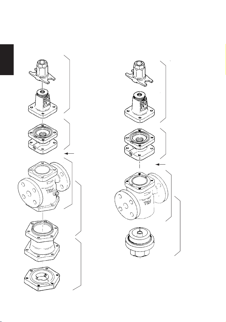
6. Disassembly and Inspection
It is a recommended practice to dismantle and inspect the COS/COSR once a year for preventive
maintenance purposes. It is especially important to do so immediately after the initial run of a new
line or before or after the equipment is out of service for a long period of time.
The size and shape of some COS and COSR parts for large valve sizes will be different from
those shown.
Adjustment Section
Pilot Section
Piston Section
Separator/
Main Valve
Section
Steam Trap
Section
Pilot
Cover
(65 - 100 mm; 2 " - 4")
see page 17
Adjustment Section
Pilot Section
Piston/
Main Valve
Section
Cover / Plug
Pilot Cover
(65 - 150 mm; 2 " - 6")
see page 17
COS COSR
2
1
/
2
1
/
English
15
Remove all steam from the piping (both upstream and downstream). If the steam supply to the
system cannot be shut off, change over to bypass operation. Close shutoff valves at the inlet
and outlet of the COS/COSR completely. Relieve residual steam pressure by loosening
slightly the spring housing bolt and pilot screen holder or sensing line plug. Wait for the body
to cool before attempting to remove the COS/COSR from the line. Then remove inlet and
outlet flange retaining bolts and trap discharge pipe union connection (COS) to permit removal
of the COS/COSR for disassembly and inspection. Secure the COS/COSR in a vise to
perform the inspection.
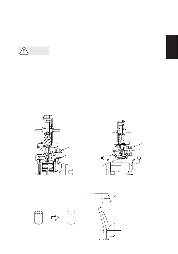
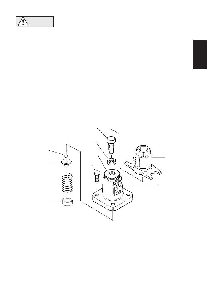
Loosen the adjustment screw completely and remove the bolts. Having removed the spring
housing, you will see the diaphragm support, coil spring, spring retainer and ball.
6.2 Disassembling the Adjustment Section
6.1 Before Disassembly
The diaphragm is removed by utilizing the notch in the pilot body. Loosen and remove the pilot
valve seat with a box wrench. Pick up the pilot valve and the pilot valve spring with a pair of
tweezers. Loosen the pilot screen holder to remove the pilot screen.
6.3 Disassembling the Pilot Section
Check for seizure or any damaged screw threads.
15 - 150 mm ( " - 6")
2
1
/
Diaphragm
Support
Coil Spring
Spring Retainer
Ball
Bolt
Locknut
Adjustment Screw
Spring
Housing
Nameplate
Spanner Cap
• Installation, inspection, maintenance, repairs, disassembly, adjustment
and valve opening/closing should be carried out only by trained
maintenance personnel.
• Be sure to use the proper components and NEVER attempt to modify the
product.
CAUTION
English
16
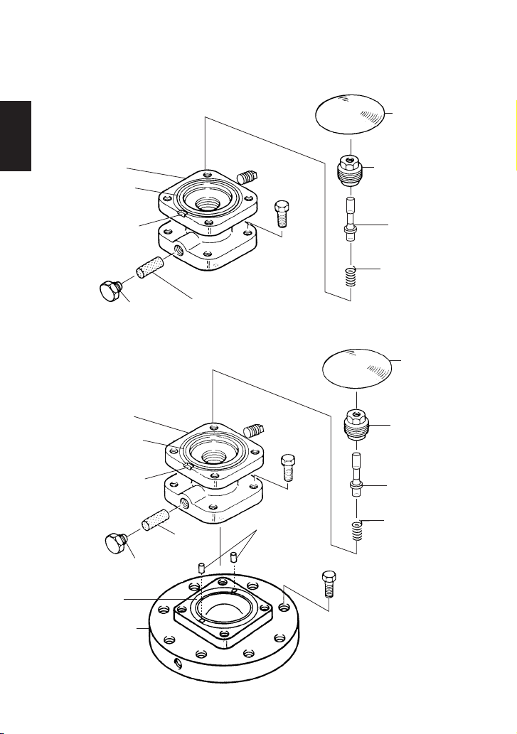
Check for any fault on the seat of the pilot valve, flaws on the gaskets, and clogging of the pilot
screen. Check for deformation, corrosion or faults on the diaphragm. The diaphragm should be
convex (open downward), with the printed UP mark on the top.
Pilot Body
Upper Pilot
Body Gasket
Notch
Pilot Screen Holder
(with Gasket)
Pilot Screen
Sensing Line Plug
Bolt
Diaphragm
Pilot Valve Seat
(with Gasket)
Pilot Valve
Pilot Valve Spring
Pilot Body
Upper Pilot
Body Gasket
Notch
Pilot Screen Holder
(with Gasket)
Pilot
Screen
Sensing Line Plug
Bolt
Bolt
Diaphragm
Pilot Valve Seat
(with Gasket)
Pilot Valve
Pilot Valve Spring
Connecting
Tubes
Pilot Cover
Lower Pilot
Body Gasket
15 - 50 mm ( " - 2")
2
1
/
65 - 150 mm (2 " - 6")
2
1
/
English
17
Remove the pilot body after loosening and removing the bolts. During this process, pay
attention not to lose the connecting tubes. Remove the piston, the cylinder and the silencer
(only sizes 65 – 150 mm
, 2 " – 6") from the main body. Then remove the piston rings and the
tension rings from the piston.
Inspect the interior of the cylinder, the exterior of the piston rings, the small hole on the piston
and the gaskets for any fault or abnormality.
6.4 Disassembling the Piston Section
NOTE: Do not apply too much force when removing the piston rings and tension rings.
The size and shape of some COS and COSR parts will be different from those shown.
Piston Ring
Tension Ring
Piston Ring
Tension Ring
Cylinder
Cylinder Gasket
Lower Pilot
Body Gasket
Connecting Tube
Main Body
Piston
Connecting Tube
Piston Ring
Tension Ring
Piston Ring
Tension Ring
Connecting Tube
Cylinder
Pilot Cover Gasket
Silencer
Main Body
Seal Ring
Piston
Connecting Tube
COS, COSR
(15 – 50 mm, " – 2")
2
1
/
COS, COSR
(65 – 150 mm, 2 " – 6")
2
1
/
2
1
/
English
18
COS
COSR
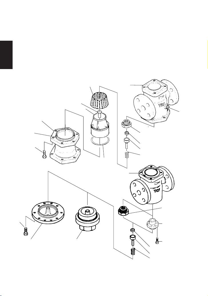
6.5
Disassembling the Separator (COS) and Main Valve (COS/COSR)
Turn the COS upside down for easy dismantling of the separator and main valve. Loosen the
bolts and remove the trap body. Be careful, as the separator may drop off when the COS is
returned to the normal attitude.
Removal of the separator and pressed-in sleeve for COS, or the cover plug for COSR, permits
removal of the main valve spring, the main valve, the main valve holder and the separator
screen. Remove the main valve seat from main the body with a box wrench.
Check for damage on the seating and sliding surfaces of the main valve and main valve holder,
the seating surface of the main valve seat and the gaskets, and for clogging of the separator
screen.
[At start-up following shutdown for a long period, always blow down the piston section of the
main body through the plug (if optional plug is supplied).]
The size and shape of some COS and COSR parts for large valve sizes will be different from
those shown.
Trap Body
Trap Body
Gasket
Bolt
Separator Screen
Main Body
Main Valve Spring
Sleeve
Separator
Corrugated
Spring
Washer
Main Valve
Main Valve Holder
Main Valve Seat
(with Gasket)
Plug
(Option)
Main Body
Bolt
Bolt
Main Valve
Main Valve Holder
Main Valve Spring
Cover (with Gasket)
COSR-3
(32 – 50 mm, 1 " – 2")
COSR-16
(32 – 150 mm, 1 " – 6")
COSR-21
(15 – 100 mm, " – 4")
4
1
/
4
1
/
2
1
/
Cover Plug (with Gasket)
COSR-3
(20, 25 mm, ", 1")
COSR-16
(15 – 25 mm, " – 1")
2
1
/
4
3
/
Main Valve Seat
(with Gasket)
(15 – 50 mm, " – 2")
Main Valve Seat
(with Gasket)
(65 – 150 mm, 2 " – 6")
2
1
/
2
1
/
English
19
COS, COSR
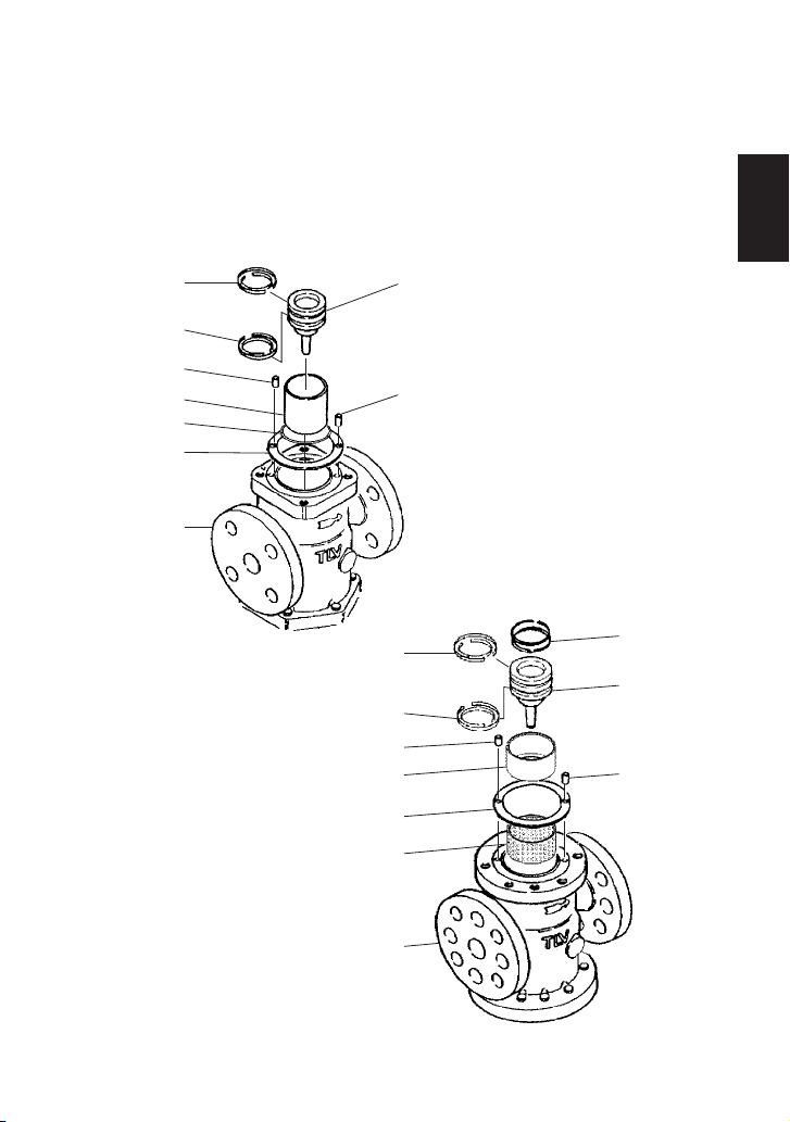
6.6 Disassembling the Steam Trap (COS)
Loosen the bolts and remove the trap cover. Be careful, as hot condensate may splash out.
6.7 Cleaning
After inspection and removal of any abnormality, clean and reassemble the parts. The following
parts will require cleaning before reassembly. A mild detergent should be used for effective
cleaning.
Remove the bolts from the trap cover and the float cover to reveal the float. Remove the float,
then loosen and remove the trap valve seat with a box wrench.
Check to verify that there is no deformation of the float, abnormality in the trap valve seat, or
dirt accumulation in the trap cover.
Main Valve Seat
Main Valve
Main Valve Holder
Piston
Piston Ring
Cylinder
Pilot Screen
Pilot Valve
Pilot Valve Seat
Adjustment Screw
Spring Retainer
Trap Valve Seat
(with Gasket)
Bolt
Spring Washer
Float Cover
Protective
Bushing
Float
Trap Cover
Gasket
Trap Cover
Guide Pin
Bolt
Trap Valve Seat
(with Gasket)
Bolt
Spring Washer
Float Cover
Protective
Bushing
Float
Trap Cover
Gasket
Trap Cover
Guide Pin
Bolt
U-nut
15 - 50 mm ( " - 2")
2
1
/
2
1
/
65 - 100 mm (2 " - 4")
Trap Cover
Float
Trap Valve Seat
Separator Screen
COS
Cover Plug / Cover
COSR
English
20
6.8 Reassembly
Assemble the unit using the same procedure as used for dismantling it, but in reverse order.
Sizes 125 and 150 mm (5" and 6") available for COSR only
Note: If a torque greater than that recommended is applied, the COS/COSR or components
may be damaged.
If drawings or other special documentation were supplied for the product, any torque given
there takes precedence over values shown here.
1. Standard torque for fastening the respective bolts are as follows:
Part
Connection Size
Distance Across Flats
Tightening Torque
Bolt for Spring Housing / Pilot Body
Pilot Valve Seat
Pilot Screen Holder
Bolt for
Pilot Body / Main Body
Bolt for Pilot Body / Pilot Cover
Bolt for
Pilot Cover / Main Body
Bolt for
Main Body / Trap Body
(COS only)
Bolt for
Trap Body / Trap Cover
(COS only)
Main Valve Seat
Bolt for
Main Valve Seat
Bolt for
Float Cover
(COS only)
Trap Valve Seat
(COS only)
Cover Plug
(COSR only)
Bolt for
Cover / Main Body
(COSR only)
(lbf・ft)
(29)
(51)
(29)
(44)
(51)
(44)
(51)
(110)
(220)
(44)
(51)
(110)
(44)
(51)
(110)
(73)
(92)
(185)
(220)
(22)
(29)
(51)
(5)
(7)
(15)
(7)
(11)
(29)
(40)
(185)
(260)
(44)
(44)
(51)
(110)
(220)
N・m
40
70
40
60
70
60
70
150
300
60
70
150
60
70
150
100
125
250
300
30
40
70
7
10
20
10
15
40
55
250
350
60
60
70
150
300
mm
17
19
24
17
19
17
19
24
36
17
19
24
17
19
24
36
41
60
70
13
17
22
8
10
13
11
13
17
19
41
46
17
17
19
24
36
All
All
All
15 – 40
50
65 – 150
65, 80
100, 125
150
15 – 40
50 – 80
100
15 – 40
50 – 80
100
15, 20
25
32, 40
50
65, 80
100, 125
150
15, 20
25 – 40
50 – 100
15, 20
25 – 40
50 – 80
100
15, 20
25
15 – 25
32, 40
50 – 80
100, 125
150
1 N・m ≈ 10 kg・cm
mm (inch)
( – 1 )
(2)
(2 – 4)
(2 , 3)
(4, 5)
(6)
( – 1 )
(2 – 3)
(4)
( – 1 )
(2 – 3)
(4)
( , )
(1)
(1 ,1 )
(2)
(2 , 3)
(4, 5)
(6)
( , )
(1 – 1 )
(2 – 4)
( , )
(1 – 1 )
(2 – 3)
(4)
( , )
(1)
( – 1)
(1 , 1 )
(2 – 3)
(4, 5)
(6)
2
1
/
2
1
/
2
1
/
2
1
/
2
1
/
2
1
/
2
1
/
2
1
/
4
1
/
2
1
/
2
1
/
2
1
/
4
3
/
2
1
/
4
3
/
2
1
/
4
3
/
2
1
/
2
1
/
4
3
/
4
1
/
2
1
/
2
1
/
2
1
/
(inch)
( )
( )
( )
( )
( )
( )
( )
( )
(1 )
( )
( )
( )
( )
( )
( )
(1 )
(1 )
(2 )
(2 )
( )
( )
( )
( )
( )
( )
( )
( )
( )
( )
(1 )
(1 )
( )
( )
( )
( )
(1 )
32
21
/
32
3
/
32
3
/
32
21
/
32
21
/
16
15
/
16
15
/
16
15
/
16
15
/
4
3
/
4
3
/
4
3
/
32
21
/
32
21
/
32
21
/
32
21
/
4
3
/
8
5
/
8
5
/
16
13
/
8
7
/
8
3
/
16
5
/
16
7
/
8
3
/
4
3
/
2
1
/
2
1
/
2
1
/
4
3
/
4
3
/
32
3
/
16
15
/
32
21
/
32
21
/
4
3
/
English
21
6.9
Regular Inspection and Maintenance
To ensure long service life, the following inspection and maintenance should be done regularly.
2. The PTFE gasket may be re-used if free from fault, crush or deformation.
3. Apply anti-seize to the threaded portion of screws and bolts, the spring retainer, ball and
adjustment screw. Apply a small amount of anti-seize to the threads of the main valve seat,
pilot valve seat and pilot screen holder. Apply anti-seize carefully to ensure it does not come
into contact with other parts.
4. Fasten the bolts one at a time in an alternating diagonal pattern to provide uniform seating.
5. After assembly, make sure that the piston and the pilot valve operate smoothly without
binding.
1) Fit the piston ring to the outside of the tension ring.
2) The ring gaps should be opposite each other.
Part Inspection and Maintenance Frequency
Separator Screen (COS only),
Pilot Screen
Disassemble and clean annually.
If there is substantial blockage, install a strainer (approx.
60 mesh) ahead of the COS/COSR.
Main Valve, Main Valve Seat,
Pilot Valve and Pilot
Valve Seat
Replace after 15,000 hours.
If there is chattering or dirt, premature wear may result.
Piston Ring
Replace after 8,000 hours.
If there is chattering or if scale build-up is severe, premature
wear may result.
Piston
Replace after 30,000 hours.
If hunting or chattering takes place, premature wear may
result.
Trap Valve Seat
Replace after 40,000 hours.
If scale build-up is severe, blockage may occur in a short
period of time.
Diaphragm
Replace after 30,000 hours.
If hunting or chattering takes place, cracks or fatigue may
develop in a short period of time.
Assembling the Piston Ring
Ring Gaps
Piston Ring
Tension Ring
English
22
 Loading...