

172-65588MA-02 (PN-COS Pneumatic Control Valve) 5 September 2014
ISO 9001/ ISO 14001
Manufacturer
Kakogawa, Japan
is approved by LRQA LTD. to ISO 9001/14001
Pneumatic Control Valve for Steam
COSPECT
PN-COS-16
Copyright © 2014 by TLV CO., LTD.
All rights reserved

Contents
1
Introduction ........................................................................ 1
Safety Considerations ........................................................ 2
Specifications ..................................................................... 4
Acceptable Operating Range ............................................. 4
Correct Usage of the PN-COS-16...................................... 5
Configuration...................................................................... 7
Installation .......................................................................... 8
Operation ......................................................................... 14
Maintenance..................................................................... 17
Disassembly..................................................................... 18
Reassembly ..................................................................... 22
Troubleshooting ............................................................... 23
Product Warranty ............................................................. 26
Introduction
Thank you for purchasing the pneumatic control valve for steam, model
COS-16
This product has been thoroughly inspected before being shipped from the factory.
When the product is delivered, before doing anything else, check the specifications
and external appearance to make sure nothing is out of the ordinary. Also be sure to
read this manual carefully before use and follow the instructions to be sure of using
the product properly.
The
pneumatic control valve for steam that utilizes the structure of the COSPECT series
pilot operated pressure reducing valve, which is our unique product. Steam-using
equipment can achieve its intended efficiency only if the steam being used is very dry.
Using steam in which matter such as condensate, scale, types of grease or air is
entrained can not only result in problems with the steam-using equipment and in
lowered productivity, but can also lead to shortened service life for and malfunction of
the control valves.
The
separator, screen, and steam trap that eliminates these problems and makes possible
the supply of very dry steam at a stable pressure.
The PN-COS-16 can operate automatically and provide accurate pressure control and
temperature control when combined with the
a general-purpose controller. (However, for process temperature control, the desired
process temperature must be controllable by a secondary pressure within the adjustable
pressure range of the PN-COS-16.) Additionally, manual remote setting or 2 point
pressure switching as a pressure reducing valve is possible by combination with an air
regulator (with relief function).
If detailed instructions for special order specifications or options not contained in this
manual are required, please contact
This instruction manual is intended for use with the model(s) listed on the front cover.
It is needed not only for installation, but also for subsequent maintenance,
disassembly/reassembly and troubleshooting. Please keep it in a safe place for future
reference.
.
pneumatic control valve for steam, model PN-COS-16 is a new type of
pneumatic control valve for steam, model PN-COS-16, has a built-in cyclone
SC-F70 digital indicator controller or
for full details.
172-65588MA-02 (PN-COS Pneumatic Control Valve) 5 Sep 2014
PN-

2
R
Safety Considerations
Read this section carefully before use and be sure to follow the instructions.
Installation, inspection, maintenance, repairs, disassembly, adjustment and valve
opening/closing should be carried out only by trained maintenance personnel.
The precautions listed in this manual are designed to ensure safety and prevent
equipment damage and personal injury. For situations that may occur as a result
of erroneous handling, three different types of cautionary items are used to
indicate the degree of urgency and the scale of potential damage and danger:
DANGER, WARNING and CAUTION.
The three types of cautionary items above are very important for safety: be sure to
observe all of them as they relate to installation, use, maintenance and repair.
Furthermore, TLV accepts no responsibility for any accidents or damage occurring
as a result of failure to observe these precautions.
Symbols
Indicates a DANGER, WARNING or CAUTION item.
DANGE
WARNING
CAUTION
WARNING
CAUTION
Indicates an urgent situation which poses a threat of death or
serious injury
Indicates that there is a potential threat of death or serious injury
Indicates that there is a possibility of injury or equipment / product
damage
NEVER apply direct heat to the float.
The float may explode due to increased internal pressure,
causing accidents leading to serious injury or damage to property
and equipment.
Install properly and DO NOT use this product outside the
recommended operating pressure, temperature and other
specification ranges.
Improper use may result in such hazards as damage to the
product or malfunctions that may lead to serious accidents. Local
regulations may restrict the use of this product to below the
conditions quoted.
DO NOT use the product in excess of the maximum
operating pressure differential.
Such use could make discharge through the steam trap
impossible (blocked).
Use hoisting equipment for heavy objects (weighing
approximately 20 kg (44 lb) or more).
Failure to do so may result in back strain or other injury if the
object should fall.
Take measures to prevent people from coming into direct
contact with product outlets.
Failure to do so may result in burns or other injury from the
discharge of fluids.
Safety considerations continued on the next page
172-65588MA-02 (PN-COS Pneumatic Control Valve) 5 Sep 2014
3
CAUTION
When disassembling or removing the product, wait until the
internal pressure equals atmospheric pressure and the
surface of the product has cooled to room temperature.
Disassembling or removing the product when it is hot or under
pressure may lead to discharge of fluids, causing burns, other
injuries or damage.
Be sure to use only the recommended components when
repairing the product, and NEVER attempt to modify the
product in any way.
Failure to observe these precautions may result in damage to the
product and burns or other injury due to malfunction or the
discharge of fluids.
Do not use excessive force when connecting threaded pipes
to the product.
Over-tightening may cause breakage leading to fluid discharge,
which may cause burns or other injury.
Use only under conditions in which no freeze-up will occur.
Freezing may damage the product, leading to fluid discharge,
which may cause burns or other injury.
Use only under conditions in which no water hammer will
occur.
The impact of water hammer may damage the product, leading to
fluid discharge, which may cause burns or other injury.
Make sure the power supply is OFF before carrying out
work on the wiring or inspections involving disassembly.
If such work is carried out with the power on, there is a danger
that equipment may malfunction or electric shock may occur,
leading to injury or other accidents.
Make sure that wiring work requiring a special license is
carried out by qualified personnel.
If carried out by unqualified personnel, overheating or short circuits
leading to injury, fires, damage or other accidents may occur.
When using this product, NEVER stand close to, or leave
tools anywhere near moving parts, such as the shaft.
Contact with moving parts or objects becoming caught in moving
parts could lead to injury or damage or other accidents.
172-65588MA-02 (PN-COS Pneumatic Control Valve) 5 Sep 2014
Specifications
CAUTION
CAUTION
Install properly and DO NOT use this product outside the recommended
operating pressure, temperature and other specification ranges.
Improper use may result in such hazards as damage to the product or
malfunctions which may lead to serious accidents. Local regulations
may restrict the use of this product to below the conditions quoted.
DO NOT use the product in excess of the maximum operating pressure
differential; such use could make discharge through the steam trap
impossible (blocked).
4
CAUTION
Use only under conditions in which no freeze-up will occur. Freezing
may damage the product, leading to fluid discharge, which may cause
burns or other injury.
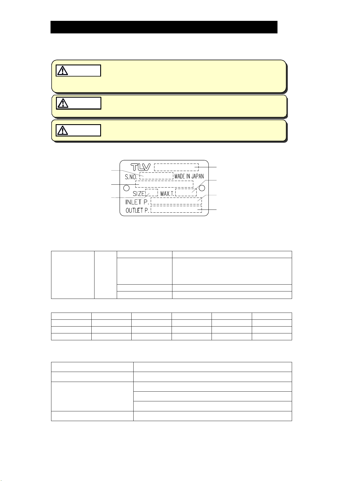
Refer to the product nameplate for detailed specifications.
Serial Number
Valve No.*
Nominal Diameter
* Valve No. is displayed for products with options. This item is omitted from the nameplate
when there are no options.
Model
Maximum Operating
Temperature
Primary Pressure Range
Secondary Pressure
Adjustable Range
<Required utilities>
Adjustment
Section
(Drive Section)
Motive
Air
Maximum Pressure 1.6 MPaG (250 psig)
Required Air Pressure [Desired secondary pressure + 0.1] MPaG
or higher
[Desired secondary pressure + 15] psig
or higher
Air Connecting Port Rc(PT), BSP or NPT 1/4"
Air Quality
Oil-free air, filtered to 5 m
(1 MPa = 10.197 kg/cm2)
<CV Value>
Size: mm (in) 15 (1/2) 20 (3/4) 25 (1) 40 (11/2) 50 (2)
CV (US) 3.8 6.9 11.1 24.0 37.2
CV (UK) 3.2 5.7 9.2 20.0 31.0
Kvs (DIN) 3.3 5.9 9.5 20.6 31.9
Acceptable Operating Range
Model PN-COS-16
Primary Pressure Range* 0.2 –1.6 MPaG (30 – 250 psig)
Adjustable Pressure Range
(All conditions must be met)
Pressure differential between 0.07
Minimum Adjustable Flow Rate 5% of rated flow rate
*For process temperature control, the desired process temperature must be controllable by a
secondary pressure within the adjustable pressure range of the PN-COS-16.
Within 10 – 84% of the primary pressure
(Minimum adjustable pressure of 0.03 MPaG (5 psig)
0.85 MPa (10 – 120 psi)
–
(1 MPa = 10.197 kg/cm2)
172-65588MA-02 (PN-COS Pneumatic Control Valve) 5 Sep 2014
Correct Usage of the PN-COS-16
5
CAUTION
Install properly and DO NOT use this product outside the recommended
operating pressure, temperature and other specification ranges.
Improper use may result in such hazards as damage to the product or
malfunctions which may lead to serious accidents. Local regulations
may restrict the use of this product to below the conditions quoted.
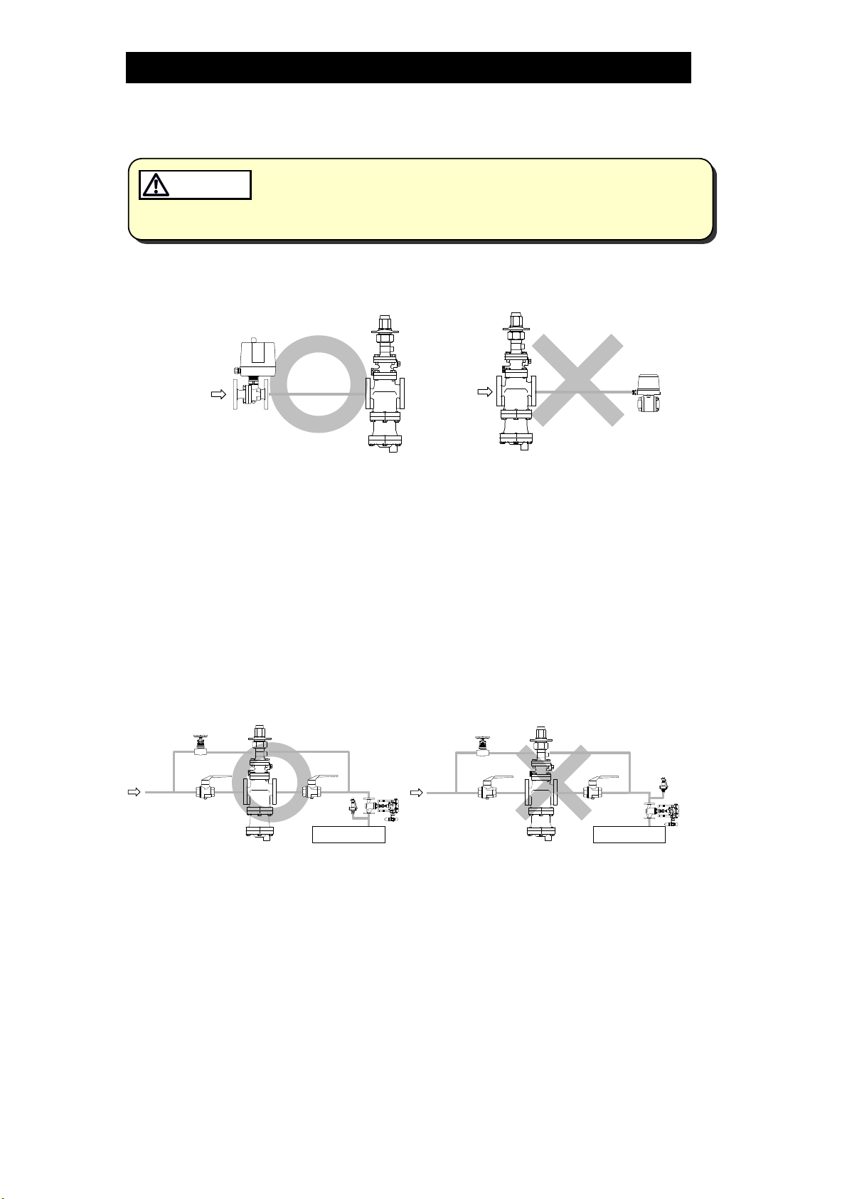
1. The PN-COS-16 should be operated only within its specifications.
2. Installing an ON / OFF Valve (Solenoid Valve or Motorized Valve)
Motorized
Valve
PN-COS
PN-COS
Solenoid
Valve
Inlet side
Outlet side
If an on-off valve, such as a motorized valve, is required to stop supply of steam
to the steam-using equipment, install it at the inlet side of the PN-COS-16. If a
solenoid valve is installed at the outlet of the PN-COS-16, its opening and
closing will cause heavy chattering and may lead to damage of the piston and
main valve. (When the on-off valve opens, the secondary pressure of the PN-
COS-16 changes from zero to the set pressure. Passing through an area of the
reducing ratio of less than 10:1, where adjustment is impossible, chattering
occurs momentarily.) To save energy, it is recommended to install the on-off
valve as near to the boiler as possible.
NOTE: To prevent water hammer, it is recommended that a slow-acting motorized
on-off valve be used. In particular, if a fast-acting on-off solenoid valve is
used for frequent temperature control, the potential water hammer effect
can damage the steam-using equipment and the PN-COS-16.
3. Installing a Control Valve
PN-COS
Control
Valve
Safety
Valve
Equipment
PN-COS
Safety
Valve
Equipment
A control valve installed between the PN-COS-16 and the steam-using equipment
(downstream of the PN-COS-16) for controlling equipment temperature may raise
the pressure between the PN-COS-16 and the control valve when the control
valve is closed, depending on the spatial relationship. A safety valve should be
installed downstream of the control valve.
NOTE: When installing a safety valve to protect the steam-using equipment, be sure
to install it on the steam-using equipment or directly before the inlet of the
steam-using equipment. If the safety valve is installed on the outlet side of
the PN-COS-16 between the PN-COS-16 and a control valve, an eventual
pressure rise could activate the safety valve.
172-65588MA-02 (PN-COS Pneumatic Control Valve) 5 Sep 2014
Control
Valve
f
f
)
c
5
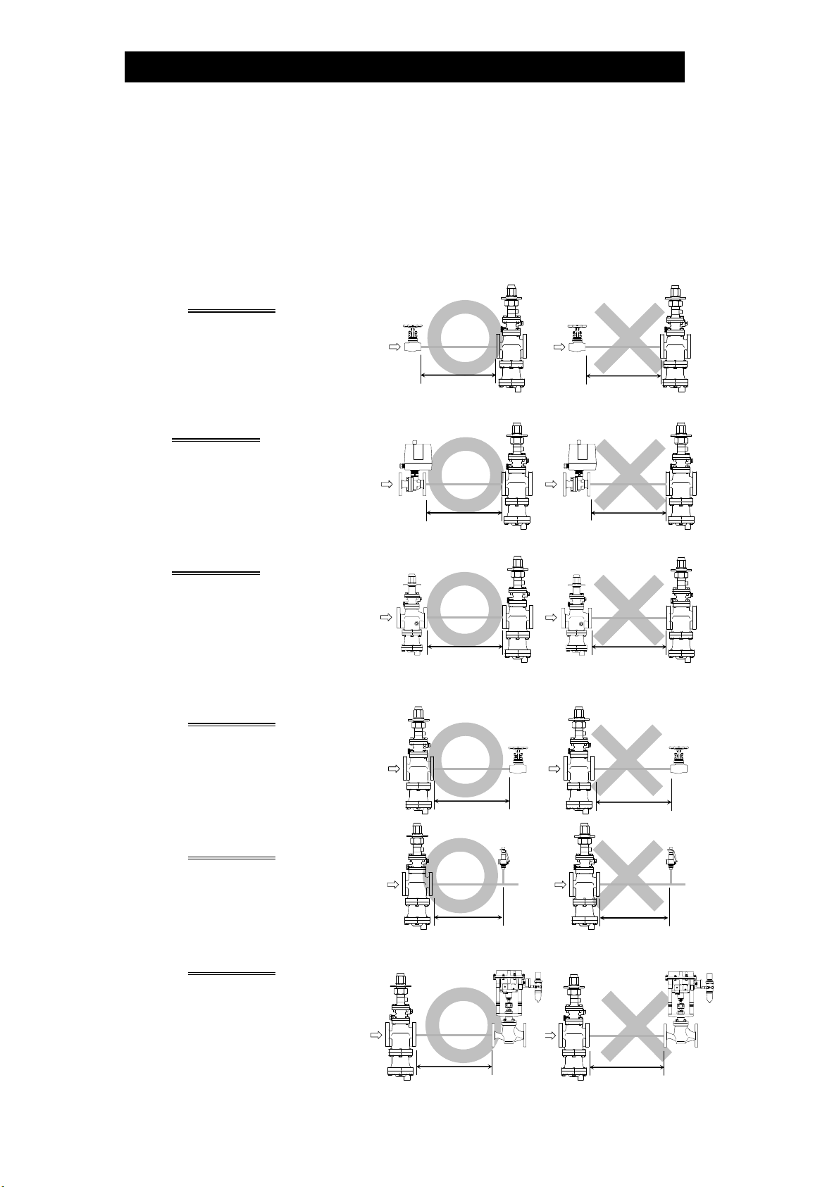
4. Precautions for the Installation of Additional Fittings Before or After the PN-COS-16
In order to ensure stable steam flow, the piping upstream and downstream of
the PN-COS-16 must be straight runs. If the PN-COS-16 is installed either
directly before or after an elbow or control valve, unevenness in steam flow
may result in chattering and unstable pressure.
To ensure stable steam flow, it is recommended that the PN-COS-16 be
installed on straight runs of piping, as illustrated below.
1) Inlet (primary side) of the PN-COS-16
Maintain a straight piping run
of 10 d or more
when a
manual valve, a strainer or an
elbow, etc.
elbow, etc. is installed.
(Example: if nominal size is 25
mm (1 in), have 250 mm (10
in) or more)
Maintain a straight piping run o
30 d or more when an
automated valve (on-off valve)
is installed.
(Example: if nominal size is 25
mm (1 in), have 750 mm (30
in) or more)
Maintain a straight piping run o
Pressure
Reducing
30 d or more when a pressure
reducing valve is installed.
(Two-stage pressure reduction
(Example: if nominal size is 25
mm (1 in), have 750 mm (30
in) or more)
2) Outlet (secondary side) of the PN-COS-16
Maintain a straight piping run
of 15 d or more
when a
manual valve, a strainer or an
elbow, etc. is installed.
(Example: if nominal size is 25
mm (1 in), have 375 mm (15
in) or more)
Maintain a straight piping run
of 30 d or more
when a
safety valve is installed.
(Example: if nominal size is 2
mm (1 in), have 750 mm (30
in) or more)
Maintain a straight piping run
of 30 d or more
when a
control valve or an automated
valve (on-off valve) is
installed.
(Example: if nominal size is
25 mm (1 in), have 750 mm
(30 in) or more)
(d = pipe diameter)
Valve,
strainer,
PN-COS
10 d or more
Valve,
strainer,
elbow, etc.
Less than
Motorized
Valve
30 d or more
Valve
30 d or more
PN-COS Valve,
15 d or more
PN-COS
30 d or more
PN-COS
PN-COS
strainer,
elbow, et
Safety
Valve
Motorized
Valve
Less than
Pressure
Reducing
Valve
Less than
PN-COS
PN-COS
Control or
Automated
Valve
PN-COS
30 d or more
PN-COS
Less than
PN-COS
10 d
PN-COS
30 d
PN-COS
30 d
Valve,
strainer,
elbow, etc.
Less than
15 d
Safety
Valve
Less than
30 d
Control or
Automated
Valve
30 d
6
172-65588MA-02 (PN-COS Pneumatic Control Valve) 5 Sep 2014
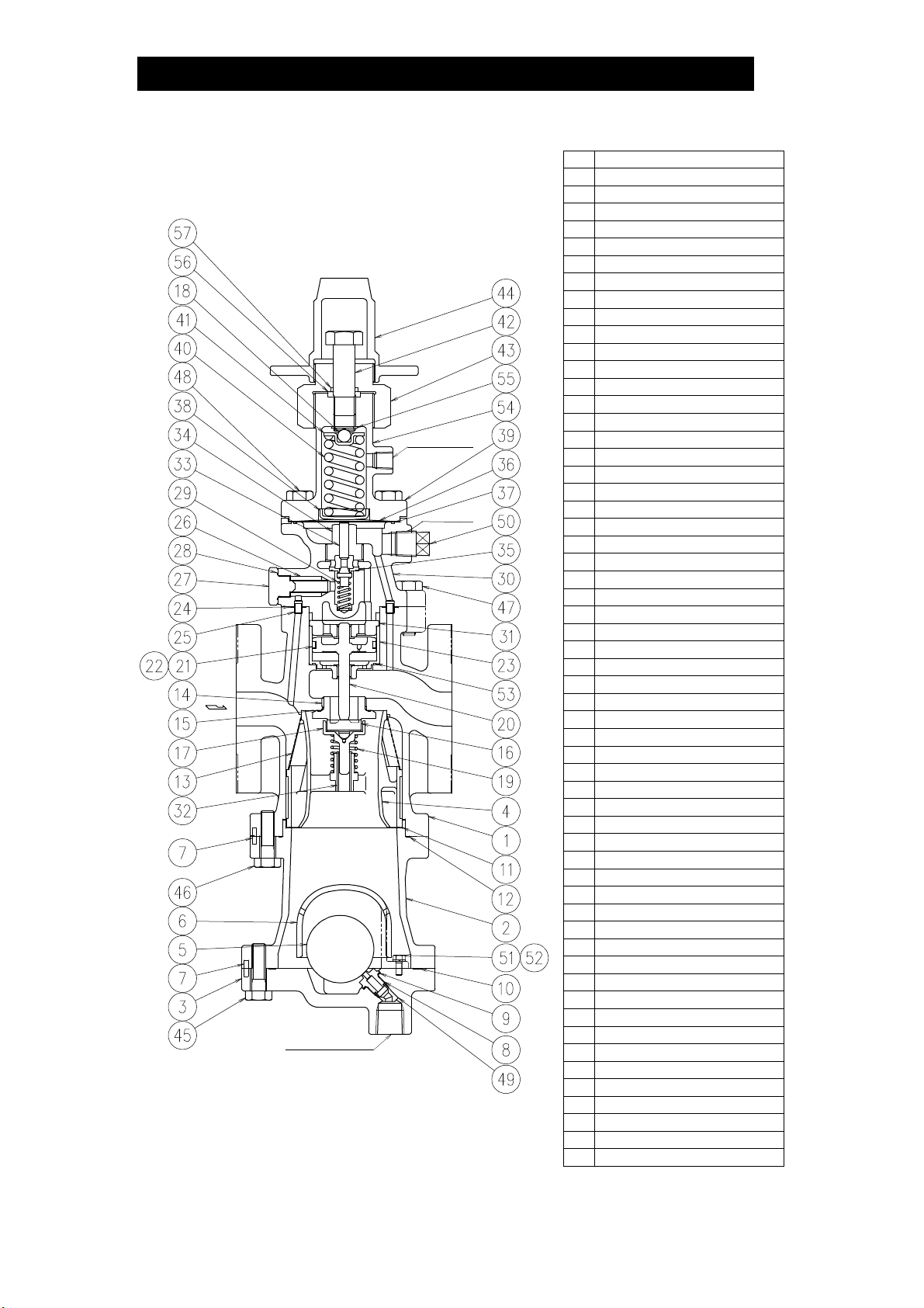
Configuration
15 – 50 mm (1/2 – 2 in)
8 mm (1/4in)
Motive Air
Port
10 mm
3
/8in)
(
15 mm (1/2in)
Condensate
Discharge Port
*North American model does not equip this plug.
7
No. Name
1 Main Body
2 Trap Body
3 Trap Cover
4 Separator
5 Float
6 Float Cover
7 Guide Pin
8 Trap Valve Seat
9 Trap Valve Seat Gasket
10 Gasket (Trap Body/Trap Cover)
11 Wave Spring
12 Gasket (Main Body/Trap Body)
13 Separator Screen
14 Main Valve Seat
15 Main Valve Seat Gasket
16 Main Valve
17 Main Valve Holder
18 Steel Ball
19 Main Valve Spring
*
20 Piston
21 Piston Ring
22 Tension Ring
23 Cylinder
24 Gasket (Pilot Body/Main Body)
25 Connecting Tube
26 Pilot Screen
27 Pilot Screen Holder
28 Pilot Screen Holder Gasket
29 Pilot Valve Spring
30 Pilot Body
31 Piston Guide
32 Sleeve
33 Pilot Valve
34 Pilot Valve Seat
35 Pilot Valve Seat Gasket
36 Diaphragm
37 Diaphragm Gasket
38 Diaphragm Support
39 Spring Housing
40 Coil Spring
41 Spring Retainer
42 Adjustment Screw
43 Packing Retainer
44 Spanner Cap
45 Hex Bolt (Trap Body/Trap Cover)
46 Hex Bolt (Main Body/Trap Body)
47 Hex Bolt (Pilot Body/Main Body)
48 He x Bol t (Spring Housing/Pilot Body)
49 Bushing
50 Plug – Sensing Line Port*
51 Float Cover Bolt
52 Spring Washer
53 Cylinder Gasket
54 Nameplate
55 C-ring
56 Gland Packing
57 O-ring
172-65588MA-02 (PN-COS Pneumatic Control Valve) 5 Sep 2014
Installation
CAUTION
CAUTION
Install properly and DO NOT use this product outside the recommended
operating pressure, temp erature and other specification ranges.
Improper use may result in such hazards as da mage t o the product or
malfunctions which may lead to serious accidents. Local regulations
may restrict the use of this product to below the conditions quoted.
Use hoisting equipmen t for heavy objects (weighing approximately
20 kg (44 lb) or more). Failure to do so may result in back strain or other
injury if the object should fall.
8
CAUTION
Take measures to prevent people from coming into direct contact with
product outlets. Failure to do so may result in burns or other injury from
the discharge of fluids.
Installation, inspection, maintenance, repairs, disassembly, adjustment and valve
opening/closing should be carried out only by trained maintenance personnel.
Installation Environment
Avoid installation in the following types of environments:
Locations with ambient temperatures above 50 °C (122 °F) or below 0 °C (32 °F)*
Locations with ambient humidity above 90% RH and below 10% RH
Locations where corrosive gas is generated
Locations with heavy vibration or shock
Locations with high inductive interference or other factors that would have a
harmful effect on electrical circuitry*
*When the PN-COS-16 is used with electrical equipment such as an electro-pneumatic
transducer, controller, etc.
1. Blowdown
Before installing the PN-COS-16 unit, be
sure to blow down all piping thoroughly. If
this is not possible, perform a blowdown
using the bypass valve.
Blowdown is especially important for newly
installed piping or after the system has
been shut down for a long period of time.
2. Removing Seal and Cap
Before installation, be sure to remove all protective seals and caps.
(Found in 3 locations, on the product inlet and outlets.)
Open
Closed
Blowdown with the Bypass Valve
PN-COS
Closed
①
②
3. Installation Angle
Install the PN-COS-16 vertically, so that the arrow
mark on the body points horizontally in the direction
of steam flow.
Allowable inclination is 10 degrees in the fore-aft
direction and 15 degrees in the plane perpendicular
to the steam flow line.
172-65588MA-02 (PN-COS Pneumatic Control Valve) 5 Sep 2014
10
10
10
10
③
15 1515 15

4. Spacer Installation
If spacing adjustment is
necessary to accommodate
installation, install a spacer on
the outlet flange.
The spacer should consist of a
spacer, gaskets, bolts and nuts.
Fit gaskets to both sides of the
spacer between the PN-COS-
16 outlet and the pipe flange.
Fasten with bolts and nuts.
5. Piping Support
Install the PN-COS-16, paying
attention to avoid excessive
load, bending and vibration.
Support the inlet and outlet
pipes securely.
Correct
spacer
location
Incorrect
spacer
location
9
6. Maintenance Space
Leave sufficient space for maintenance, inspection
and repair.
(Unit: mm (in))
7. Trap Outlet Pipe
For ease of maintenance, installation of
a union connection is recommended for
the trap outlet pipe.
Connect the outlet pipe to a condensate
return line, or extend it to a trench. In the
case of the latter, make sure the end of
the pipe is above the waterline. (Dirt and
water may be sucked up by the vacuum
formed during trap closure and system
shutdown.)
200 (8)
150
(6)
150
(6)
100 (4)
200
(8)
200
(8)
Small Hole
172-65588MA-02 (PN-COS Pneumatic Control Valve) 5 Sep 2014

10
8. Pressure Sensor Installation (for
pressure control)
Pressure
Gauge
PN-COS
Pressure
Sensor
The length of piping between the
PN-COS-16 and the pressure
sensor should be no more than 5 m
(17 ft). If the piping distance is too
great, pressure loss and delay of
pressure change along this distance
will increase, resulting in steam flow
rate fluctuations.
Straight
>>>>
15 d or
>
5 m (17 ft) or less
more
Distance of
pipe
Straight
pipe
5 d or
more
>>>
Steam fluctuations at the pressure sensor may impair the stability of the pressure
control. Ensure a straight piping run of at least 15 d upstream and 5 d
downstream from the pressure sensor.
9. Blowdown Valve (requires an optional plug)
In an environment of heavy dirt or scale, or when the steam-using equipment is
used only periodically, such as for room heating equipment, be sure to use a
blowdown valve.
1) Remove the plug (option) from the main body.
2) Install the blowdown valve.
3) Open the blowdown valve and blow any residual dirt
and scale off of the screen.
Remove the
10 mm (
(optional)
and install the
blowdown valve
3
/8in) plug
4) Periodically activate the blowdown valve to keep the
system free of dirt and scale.
>>
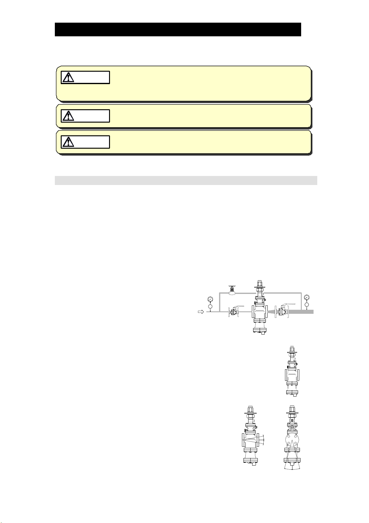
10. Piping Size
If the secondary steam flow velocity is expected to be more than 30 m/s (100 ft/s),
install a diffuser in order to keep the flow velocity below 30 m/s (100 ft/s).
If the distance between the PN-COS-16 and the steam-using equipment is great,
a possible drop in pressure should be taken into consideration when selecting the
piping size.
In addition, when installing the strainer, the strainer screen should be either at the
3 o’clock or 9 o’clock position to prevent condensate accumulation.
PN-COS
PN-COS
PN-COS
PN-COS
Diffuser
Diffuser
Diffuser
Diffuser
PN-COSPN-COS
Straight-run piping lengths (d = pipe diameter):
Straight-run piping lengths (d = pipe diameter):
Straight-run piping lengths (d = pipe diameter):
Straight-run piping lengths (d = pipe diameter):
Upstream = 10 d or more; Downstream = 15 d or more
Upstream = 10 d or more; Downstream = 15 d or more
172-65588MA-02 (PN-COS Pneumatic Control Valve) 5 Sep 2014

11. Two-stage Pressure Reduction
Whenever the pressure cannot be reduced to the desired level with a single PN-
COS-16 due to operating range limitations, such as when the reduction ratio is
greater than 10:1, the pressure reducing valve should be installed at the primary
side.
Shut-off
Valve
Pressure
Gauge
Pressure
Reducing
Valve
Bypass
Valve
Shut-off
Valve
Pressure
Gauge
Shut-off
Valve
Bypass
Pressure
Gauge
Primary
Side
Valve
Primary
Side
Bypass
Valve
Shut-off
Valve
PN-COS
Shut-off
Valve
PN-COS
Shut-off
Valve
Safety Valve
(Relief Valve)
Pressure
Gauge
Safety Valve
(Relief Valve)
Pressure
Gauge
12. Accessories
Always install a shut-off valve, pressure gauge and bypass line at both inlet and
outlet.
Ball valves, which will not retain condensate, are recommended for inlet and outlet
shut-off valves. The bypass pipe should be at least
1
/2 of the size of the inlet
(primary side) pipe.
Pressure
Gauge
Globe
Valve
PN-COS
Pressure
Gauge
PN-COSPN-COS
11
Ball Valve
Ball Valve
13. External secondary pressure-sensing line (when required)
North American Models:
North American Models are factory prepared for external sensing.
An external sensing line MUST be installed.
DO NOT SUPPLY STEAM until all piping and a 10 mm (
3
/8 in) secondary pressure
sensing line with a slightly falling pitch have been properly installed. Install a
shutoff valve in the pressure sensing line for maintenance purposes.
CAUTION
Keep the shutoff valve open at all times during operation. If the shutoff
valve is closed,PN-COS-16 will fully open and PRIMARY PRESSURE WILL BE
SUPPLIED TO THE EQUIPMENT (see “Piping Examp le” on next page).
Non-North American Models:
Factory-standard PN-COS-16 employs an internal secondary pressure-sensing
channel built into the body, saving the need to install an external pressure-sensing
line to detect the secondary pressure.
Installation of an external secondary pressure-sensing line involves closing the
internal pressure-sensing channel and installing a line from the sensing line port to
the point where pressure should be controlled. This can increase stability of
pressure control where steam loss in secondary piping and flow rate fluctuation is
high. In addition, the rated flow rate will be greater than an internal pressure-
172-65588MA-02 (PN-COS Pneumatic Control Valve) 5 Sep 2014

12
sensing channel under the operational pressure reduction ratio of 2:1 or more.
Installation procedure
1) Loosen and remove the bolts that attach the pilot body to the main body and
remove the pilot body.
2) Install the blind pin (optional) by first removing the connecting tube from the
main body or pilot cover and then substituting the blind pin.
3) Re-install the pilot body and fasten the bolts evenly to the proper torque
(see the torque chart in the “Reassembly” section).
4) Remove the plug from the secondary pressure sensing line port and connect
the secondary pressure sensing line.
5) Install the secondary pressure sensing line with a slightly falling pitch. The end
of the secondary pressure sensing line should be connected to the place on
the main piping where the pressure is to be sensed (see the piping example on
the next page). A shut-off valve and union should be installed in the secondary
pressure sensing line.
Pilot Body
Body
Piping Example:
PN-COS
Secondary Pressure Sensing Line Port
(Rc(PT)
3
/
BSP3/8or NPT 3/8)
8,
Hex Bolt
Secondary Pressure
Sensing Port
Connecting Tube
Replace the factory-installed
connecting tube (has a hole)
with the optional blind pin
(has no hole).
Connecting
Tube
Ball
Valve
<>
10 mm (3/8 in)
Pressure Sensing Line
(with a slightly falling pitch towards
the sensing point)
15 d
>
<
or more
Blind Pin
1 m (3.3 ft) or 15 d,
whichever is larger
Steam-using EquipmentSteam-using Equipment
172-65588MA-02 (PN-COS Pneumatic Control Valve) 5 Sep 2014

14. Internal sensing for North American models
All models except North American models are factory prepared for internal sensing.
When internal pressure sensing is required for North American models, please
contact the nearest TLV representative to request both a connecting tube, which
must be installed in place of the blind pin, and a threaded secondary pressure
sensing plug. Follow the connecting tube installation procedure shown below:
1) Loosen and remove the four (4) bolts that attach
the pilot body to the main body and remove the
pilot body.
2) Install the connecting tube by first removing the
blind pin from the secondary side of the main body
and then substituting the connecting tube.
3) Re-install the pilot body and fasten the four (4) bolts evenly.
See the torque chart in the “Reassembly” section in this manual for torque
requirements of these bolts.
4) If a secondary pressure sensing pipe has previously been installed, remove it
and be certain to install the threaded secondary pressure sensing line plug in its
place.
NOTE: When 15 mm (
(45 psig) and 0.1 MPaG (15 psig) respectively, and below 50% of primary
pressure, internal sensing may provide decreased capacity (Rated Flow
Rate) compared to external sensing.
Verify the capacity before switching to internal sensing.
1
/2 in) or 20 mm (3/4 in) PN-COS-16 is used below 0.3 MPaG
Blind Pin
Connecting Tube
13
172-65588MA-02 (PN-COS Pneumatic Control Valve) 5 Sep 2014

Operation
CAUTION
Procedure
The system configuration examples (diagrams) shown in this section are for
explanation purposes only, and are not intended as installation designs.)
Automatic Control
<Example: Pressure control system (as control valve)>
When u sing this product, NEVER stand close to, or leave tools anywhere
near moving parts, such as the shaft. Contact with moving parts or objects
becoming caught in moving parts could lead to injury or damage or other
accidents.
14
Controller
Air
Regulator
Electro-Pneumatic
Transducer
PN-COS-16
Transmitter
<Example: Temperature control (as control valve)>
Air
Regulator
Electro-Pneumatic
Transducer
PN-COS-16
Controller
Pressure
Automatic control is possible when the PN-COS-16 is used with a controller. However,
an electro-pneumatic transducer is required in order to control the air for operation.
The wiring, etc. should be carried out according to the instruction manual for the
controller, the electro-pneumatic transducer, or related devices.
Please set the position of the adjustment screw on the PN-COS-16 according to the
steps shown in the “Setting the pressure with the adjustment screw”.
In addition, for process temperature control, the secondary pressure of the PN-COS-16
needs to be within the pressure adjustable range at the time of normal operation.
172-65588MA-02 (PN-COS Pneumatic Control Valve) 5 Sep 2014

A
r
Manual Control
<Example: Manual remote operation (as pressure reducing valve)>
15
Air
Regulator
(with relief)
PN-COS-16
(installed in a
high position)
When operating the PN-COS-16 remotely by manual operation, an air regulator (with
relief function) that adjusts motive air pressure is required. Adjust the set pressure
with the air regulator while checking the pressure gauge on the secondary side.
Please set the position of the adjustment screw according to the steps shown in the
"Setting the pressure with an adjustment screw" on the following page.
<Example: 2 point pressure switching (as pressure reducing valve)>
ir Regulato
(with relief)
3 Way
Solenoid Valve
ON/OFF
Switch
PN-COS-16
Pressure at the secondary side can be switched manually between 2 points with an
ON/OFF switch. To do so, an air regulator (with relief function), which adjusts the
motive air, a 3 way solenoid valve, and an ON/OFF switch are required.
Pressure setting at the higher pressure side should be adjusted with the motive air by
checking the pressure gauge at the secondary side. For pressure setting at the lower
pressure side, follow the steps in the "Setting the pressure with the adjustment screw"
below.
Setting the pressure with the adjustment screw
Other than setting the secondary steam pressure of PN-COS-16
Adjustment
Screw
using air pressure, it can be set by the adjustment screw.
・ To Maintain minimum required pressure by adjustment screw
Set the steam pressure at the secondary pressure side to a
minimum required pressure using the adjustment screw.
・ When setting the pressure using only motive air
Loosen the adjustment screw until there is no load on the coil
spring. The valve should be closed once there is no motive air.
172-65588MA-02 (PN-COS Pneumatic Control Valve) 5 Sep 2014

16
<Adjustment>
1. It is necessary to blow down all pipe lines thoroughly. The blowdown is especially
important if the line is new or has been shut down for a long period of time. Take
particular care to ensure that matter such as condensate and dirt does not remain
inside the steam-using equipment. (Stay clear of any pressurized blow-out from the
safety valve.)
2. Make sure that the shut-off valve and the bypass valve located upstream and
downstream of the PN-COS-16 are completely closed.
3. Remove the spanner cap and turn the adjustment screw counterclockwise to
reduce tension on the coil spring.
NOTE: Do not pull up the adjustment screw forcibly once the adjustment screw has
reached the point at which it stops. The internal stopper (C-ring) may break.
4. Slowly, fully open the shut-off valve at the inlet of the PN-COS-16. Allow sufficient
time for condensate remaining at the inlet of the PN-COS-16 to be discharged
through the built-in steam trap.
5 . Slightly open the shut-off valve at the outlet of the PN-COS-16.
6. Turn the adjustment screw clockwise until the desired outlet pressure is obtained.
Wait several minutes.
Clockwise
Tighten the adjustment screw
to increase pressure
7. Slowly, fully open the shut-off valve at the secondary side of the PN-COS-16. After
setup, put the spanner cap back on.
8. When shutting down the system, always close the shut-off valve at the outlet first
and then the inlet.
Loosen the adjustment screw
to decrease pressure
Counterclockwise
172-65588MA-02 (PN-COS Pneumatic Control Valve) 5 Sep 2014

Maintenance
CAUTION
Take measures to prevent people from coming into direct contact with
product outlets. Failure to do so may result in burns or other injury from
the discharge of fluids.
17
CAUTION
CAUTION
Operational Check
Be sure to use only the recommended components when repairing the
product, an d NEVER attempt to modi fy th e product in any way. Failur e to
observe these precautions may result in damage to the product or burns
or other injury due to malfunction or the discharge of fluids.
Make sure the external power supply switch is OFF before carrying out
work on the wiring or inspections involving disassembly.
If such work is carried out with the power on, there is a danger that
equipment may malfunction or electric shock may occur, leading to
injury or other accidents.
To ensure long service life of the PN-COS-16, the following inspection and
maintenance should be performed regularly.
Part Inspection and Maintenance Frequency
Screens
(Separator, Pilot)
Main Valve, Main Valve
Seat, Pilot Valve and Pilot
Valve Seat
Piston Ring Replace after approximately 8,000 hours.
Piston Replace after approximately 30,000 hours.
Trap Valve Seat Replace after approximately 40,000 hours.
Diaphragm Replace after approximately 30,000 hours.
Disassemble and clean annually.
If there is substantial blockage, install a strainer
(approximately 60 mesh) ahead of the PN-COS-16.
Replace after approximately 15,000 hours.
If there is chattering or dirt, premature wear may result.
If there is chattering or if scale build-up is severe,
premature wear may result.
If hunting or chattering takes place, premature wear may
result.
If scale build-up is severe, blockage may occur in a short
period of time.
If hunting or chattering takes place, cracks or fatigue may
develop in a short period of time.
172-65588MA-02 (PN-COS Pneumatic Control Valve) 5 Sep 2014

Disassembly
WARNING
NEVER apply d irect heat to the float . The floa t may explod e due to
increased internal pressure, causing accidents leading to serious injury
or damage to proper ty and equipment.
18
CAUTION
CAUTION
Use hoisting equipmen t for heavy objects (weighing approximately
20 kg (44 lb) or more). Failure to do so may result in back strain or other
injury if the object should fall.
When disassembling or removing the product, wait until the internal
pressure equa ls atm ospheric pr essure and the surface of the product
has cooled to room temperature. Disassembling or removing the
product when it is hot or under pressure may lead to discharge of fluids,
causing burns, other injuries or damage.
It is a recommended practice to dismantle and inspect the PN-COS-16 once a year for
preventive maintenance purposes. It is especially important to perform an inspection
immediately after the initial run of a new line or before or after equipment such as a
heater is out of service for a long period of time. (Installation, inspection, maintenance,
repairs, disassembly, adjustment and valve opening/closing should be carried out only
by trained maintenance personnel.)
Remove all steam from the piping (both upstream and downstream). Stop supplying
motive air to the PN-COS-16. Remove the spanner cap, and then pull up the
adjustment screw until there is no load on the coil spring. Wait for the body to cool
before attempting to remove the PN-COS-16 from the line as it may be heated with the
residual heat of steam. Then remove the inlet and outlet flange retaining bolts and
nuts to permit removal of the PN-COS-16. Secure the PN-COS-16 in a vise to perform
the inspection.
Disassembling the Adjustment Section (Drive Section)
Make sure that the position of the adjustment screw is such that no load is applied to
the coil spring.
Remove the hex bolts and then take off the spring housing. Remove the C-ring with
an appropriate tool to remove the adjustment screw. Remove the adjustment screw by
loosening it. Then remove the packing retainer by turning it counterclockwise.
Adjustment Screw
Packing Retainer
Hex Bolt
Ball
Spring Retainer
O-ring
Gland Packing
Coil Spring
Diaphragm Support
Spring Housing
C-ring
Spanner Cap
NOTE: Make sure that there are no scratches or wear on the internal parts. Do not reuse the
O-ring and the gland packing.
172-65588MA-02 (PN-COS Pneumatic Control Valve) 5 Sep 2014

19
Disassembling the Pilot Section
The diaphragm is removed by utilizing the notch in the pilot body. Loosen the pilot valve
seat with a box wrench and remove it. Lift the pilot valve spring up and out with a pair of
tweezers. Then loosen and remove the pilot screen holder to remove the pilot screen.
Check for any fault on the seating surface of the pilot valve, flaws on the gaskets,
and clogging of the pilot screen.
Check for deformation, corrosion or faults on the diaphragm. The diaphragm should
be convex (open downward), with the printed UP mark on the top.
Pilot Body
Plug
Diaphragm
Upper
Pilot Body
Gasket
Notch
Pilot Valve Seat
(with Gasket)
Pilot Valve Stem
Pilot Valve
Pilot Valve Spring
Pilot Screen
Pilot Screen Holder
(with Gasket)
Disassembling the Piston Section
Hex Bolt
Take the pilot body off after removing the hex bolts. During this process, pay attention
not to lose the connecting tubes (2 pcs).
Remove the piston guide, piston and cylinder from the main body. Then remove the
piston rings and the tension rings from the piston. Do not apply too much force when
removing the piston rings and tension rings.
Check the interior of the cylinder, the exterior of the piston rings, the small hole on
the piston and the cylinder gasket for any fault or abnormality.
Piston Guide
Piston Ring
Tension Ring
Connecting Tube
Lower Pilot
Body Gasket
Piston
Cylinder
Cylinder Gasket
Main Body
172-65588MA-02 (PN-COS Pneumatic Control Valve) 5 Sep 2014

20
Disassembling the Separator / Main Valve Section
Turn the PN-COS-16 upside down for easy dismantling of the separator and main
valve. Loosen the hex bolts and remove the trap body. Be careful, as the separator
may drop off when the PN-COS-16 is returned to the normal attitude.
Removal of the separator and pressed-in sleeve permits removal of the main valve,
main valve holder, main valve spring and separator screen.
Loosen the main valve seat with a socket wrench and remove it from the main body.
Check for damage on the seating surfaces of the main valve and main valve seat,
gaskets, and sliding surfaces of each part, and for clogging of the separator screen.
Main Body
Separator Screen
Sleeve
Separator
Trap Body
Gasket
Hex
Bolt
Wave Spring
Disassembling the Steam Trap Section
Loosen the hex bolts (for the trap cover)
and remove the trap cover. Be careful,
as hot condensate may splash out.
Remove the hex bolts (for the float
cover) and remove the float cover to
reveal the float. Remove the float, then
loosen the trap valve seat with a socket
wrench and remove it.
Check to determine that there is no
deformation of the float, abnormality in
the trap valve seat or dirt accumulation
in the trap cover.
Spring Washer
Trap Valve Seat
Trap Valve Seat
Gasket
Hex Bolt
Main Valve Seat
Gasket
Main Valve Seat
Main Valve
Main Valve Holder
Main Valve Spring
Hex Bolt
Spring Washer
Float
Gasket
Trap Cover
Hex Bolt
172-65588MA-02 (PN-COS Pneumatic Control Valve) 5 Sep 2014

21
Cleaning
After inspection and removal of any abnormality, clean and reassemble the parts. The
following parts will require cleaning before reassembly:
Trap Cover Piston
Float Piston Ring
Trap Valve Seat Cylinder
Pilot Screen Separator Screen
Main Valve Seat Pilot Valve
Main Valve
Pilot Valve Seat
Main Valve Holder
It is permissible to clean using water, however cleaning with a mild detergent is
recommended for more effective cleaning.
(Coat threaded position with anti-seize after cleaning.)
Exploded View
Adjustment Section
(Drive Section)
Pilot Section
Piston Section
Separator /
Main Valve Section
Steam Trap Section
NOTE: Configuration of each part varies depending on nominal size.
172-65588MA-02 (PN-COS Pneumatic Control Valve) 5 Sep 2014

22
Reassembly
Assemble the unit using the same procedure as used for disassebling it; but in reverse
order. Observe the following precautions:
1. The PTFE gaskets may be re-used if free from fault, crushing or deformation.
2. Apply anti-seize to the threaded portion of screws and bolts and adjustment screw.
Apply a small amount of anti-seize to the threads of the main valve seat, pilot valve
seat and screen holder to ensure it does not come into contact with other parts.
3. Fasten the bolts one at a time in an alternating diagonal pattern to provide uniform
seating.
4. After the assembly, make sure that the piston and the pilot valve operate smoothly
without binding.
1) Fit the piston ring to the outside of the
2) The ring gaps should be opposite each
tension ring.
other.
5. Standard fastening torque and the distance across flats for the tools to be used
are as follows:
PN-COS-16
Part
Connection Size
(mm) (in) (mm) (in) (N·m) (lbf·ft)
Bolts
(Spring Housing/
15 – 50 17 (
Pilot Body)
Pilot Valve Seat 15 – 50 19 (3/4) 70 (51)
Pilot Screen
Holder
15 – 50 24 (
15 – 40 (1/2 – 11/2) 17 (21/32) 60 (44) Hex Bolts
(Pilot body/ Main
Body)
50 (2) 19 (
15 – 40 (1/2 – 11/2) 17 (21/32) 60 (44) Hex Bolts
(Main Body/ Trap
Body and Trap body/
Trap Cover)
Main Valve Seat
50 (2) 19 (
15, 20 (1/
3
/4) 36 (17/16) 100 (73)
2,
25 (1) 41 (15/8) 125 (92)
40 (11/2) 60 (23/8) 250 (185)
Hex Bolt
(Float Cover)
Trap Valve Seat
50 (2) 70 (2
15, 20 (1/
25, 40 (1, 11/2) 10 (3/8) 10 (7)
50 (2) 13 (
15, 20 (1/
3
/4) 8 (5/16) 7 (5)
2,
3
/4) 11 (7/16) 10 (7)
2,
25, 40 (1, 11/2) 13 (1/2) 15 (11)
50 (2) 17 (
NOTE: -If a torque greater than that recommended is applied, the body or components may
be damaged.
-Coat all threaded portions with anti-seize.
-If drawings or other special documentation were supplied for the product, any torque
given there takes precedence over values shown here.
Distance
Across Flats
21
/32) 40 (29)
15
/16) 40 (29)
3
/4) 70 (51)
3
/4) 70 (51)
3
/4) 300 (220)
1
/2) 20 (15)
21
/32) 40 (29)
Tightening Torque
(1 Nm 10 kgcm)
172-65588MA-02 (PN-COS Pneumatic Control Valve) 5 Sep 2014

Troubleshooting
WARNING
NEVER apply d irect heat to the float . The floa t may explod e due to
increased internal pressure, causing accidents leading to serious injury
or damage to proper ty and equipment.
23
CAUTION
CAUTION
When disassembling or removing the product, wait until the internal
pressure equa ls atm ospheric pr essure and the surface of the product
has cooled to room temperature. Disassembling or removing the
product when it is hot or under pressure may lead to discharge of fluids,
causing burns, other injuries or damage.
When u sing this product, NEVER stand close to, or leave tools anywhere
near moving parts, such as the shaft. Contact with moving parts or objects
becoming caught in moving parts could lead to injury or damage or other
accidents.
This product is shipped after stringent checks and inspection and should perform its
intended function for a long period of time without failure. However, should there be
any problem encountered in the operation of the PN-COS-16, consult the
troubleshooting guide below.
Trouble could occur in the drive section, pressure-reducing section (including
separator and trap sections), or the controller used together with the PN-COS-16.
The location where the trouble has occured should be identified first.
<Diagnosis of malfunctions in the pressure-reducing section>
Problems are classified as follows:
1. The secondary pressure does not increase.
2. The secondary pressure cannot be adjusted or increases abnormally.
3. Hunting (fluctuation of the secondary pressure) occurs.
4. Chattering (a heavy mechanical noise) occurs.
5. Abnormal noises.
6. Steam leaks from the steam trap or condensate is not discharged.
Major causes for the above problems are usage under non-specified conditions (out of
specifications), insufficient pressure or flow rate, and clogs by dirt and scale.
Problem Symptom Cause Remedy
The secondary
pressure does
not rise
The secondary
pressure
cannot be
adjusted or
increases
abnormally
The PN-COS-16
body is not warm
The body is warm,
but the pressure
does not increase
Adjustment is
difficult, and set
pressure varies
No steam is being
supplied or the valve at
the primary side is closed
The strainer at the primary
side or the separator
screens is clogged
No motive air is being
supplied
The pilot screen is
clogged
The flow rate is too low Check the flow rate; check
The piston is clogged with
dirt
Troubleshooting continued on the next page
Check the primary piping
and valves
Clean or blow down
Check the motive air
supply line
Clean
the model selection,
replace with a unit that has
a smaller nominal
diameter or a more
suitable unit if necessary
Clean
Check the piston ring
172-65588MA-02 (PN-COS Pneumatic Control Valve) 5 Sep 2014

Problem Symptom Cause Remedy
The secondary
pressure
cannot be
adjusted or
increases
abnormally
Hunting or
chattering
occurs
Adjustment is
difficult, and set
pressure varies
Upon closing the
valves on the
secondary side,
the secondary
pressure abruptly
rises as high as
the primary
pressure
Occurs at low
steam demand
Hunting never stops
Chattering never
stops
The piston rings are worn Replace with new piston
rings
The small hole in the
piston is clogged
There is a build-up of dirt
on the sliding surfaces of
the pilot valve, piston or
main valve
The setting for the motive
air is inappropriate
Flow rate exceeds rated
flow rate
The adjustment screw has
seized
The diaphragm is
distorted or damaged
There is fluctuation in
steam consumption
The PN-COS-16 is
inappropriate for the
service conditions
(specifications)
The bypass valve is
leaking
There is a build-up of dirt
on or damage to the pilot
valve seat or main valve
seat
It is being used below the
minimum adjustable flow
rate
There is too high a
reduction ratio (operated
at below 10% of the
primary pressure)
The PN-COS-16 is
inappropriate for the
service conditions
(specifications)
Condensate is contained,
or the trap is blocked
The PN-COS-16 is
inappropriate for the
service conditions
(specifications)
Troubleshooting continued on the next page
Clean
Clean
Check the motive air
supply line; check the set
pressure
Check the flow rate,
replace with a larger size
Replace with a new
adjustment screw
Replace with a new
diaphragm
Check the flow rate;
replace the PN-COS-16 if
necessary
Check the model
selection, replace the PN-
COS-16 if necessary
Check, clean, and replace
with a new bypass valve if
necessary
Clean
Align
Replace if necessary
Replace with a smaller
size
Use two-stage reduction
Check the model
selection, replace the PN-
COS-16 if necessary
Check the trap
Check the piping
Check the model
selection, replace the PN-
COS-16 if necessary
24
172-65588MA-02 (PN-COS Pneumatic Control Valve) 5 Sep 2014

Problem Symptom Cause Remedy
Abnormal noises Makes a high-
pitched noise
Faulty steam
trap
Steam is blowing
No condensate is
discharged
There is too high a
reduction ratio, the flow is
too great, or there is a
high-speed open/close
valve nearby
There is a build-up of dirt
on the trap valve seat or
at the float base
The body is installed tilted Check the piping
The float is deformed Check for water hammer
There is vibration in the
piping
The primary pressure
exceeds the trap valve
seat maximum operating
pressure
Water is inside the float Replace with a new float
The secondary piping is
clogged
The trap valve seat is
clogged
Use two-stage reduction
Check the flow rate, use
a larger size
Install the valve as far
away as possible
Clean
Replace with a new float
Secure the piping
Adjust the primary
pressure
Check the piping
Clean
Clean
Replace with a new trap
valve seat
25
172-65588MA-02 (PN-COS Pneumatic Control Valve) 5 Sep 2014

26
Product Warranty
1. Warranty Period
One year following product delivery.
2. Warranty Coverage
TLV CO., LTD. warrants this product to the original purchaser to be free
from defective materials and workmanship. Under this warranty, the product
will be repaired or replaced at our option, without charge for parts or labor.
3. This product warranty will not apply to cosmetic defects, nor to any product
whose exterior has been damaged or defaced; nor does it apply in the
following cases:
1) Malfunctions due to improper installation, use, handling, etc., by other
than TLV CO., LTD. authorized service representatives.
2) Malfunctions due to dirt, scale, rust, etc.
3) Malfunctions due to improper disassembly and reassembly, or
inadequate inspection and maintenance by other than TLV CO., LTD.
authorized service representatives.
4) Malfunctions due to disasters or forces of nature.
5) Accidents or malfunctions due to any other cause beyond the control of
TLV CO., LTD.
4. Under no circumstances will TLV CO., LTD. be liable for consequential
economic loss damage or consequential damage to property.
* * * * * * *
For Service or Technical Assistance:
Contact your
representative or your regional office.
Manufacturer
881 Nagasuna, Noguchi
Kakogawa, Hyogo 675-8511 JAPAN
Tel: 81–(0)79–427–1800
CO., LTD.
172-65588MA-02 (PN-COS Pneumatic Control Valve) 5 Sep 2014
 Loading...