

172-65185A-08 (MC-COSR Multi-control Valve) 20 November 2014
ISO 9001/ ISO 14001
Manufacturer
Kakogawa, Japan
is approved by LRQA LTD. to ISO
High-precision Multi-control Valve for Steam
MC-COSR-3/MC-COSR-16
Actuator: MC-GA2
Manufacturer
881 Nagasuna, Noguchi, Kakogawa, Hyogo, 675-8511 Japan
Tel: [81]-(0)79-422-1122 Fax: [81]-(0)79-422-0112
Copyright © 2014 by TLV Co., Ltd. All rights reserved

1
Contents
Introduction......................................................................... 1
Safety Considerations ........................................................ 2
Specifications ..................................................................... 4
Correct Usage of the MC-COSR Multi-control Valve .......... 6
Configuration ...................................................................... 8
Installation......................................................................... 12
Wiring................................................................................ 18
Setting the Valve Coefficient ............................................ 20
Operation.......................................................................... 21
Inspection and Maintenance.............................................23
Disassembly .....................................................................24
Reassembly...................................................................... 29
Troubleshooting................................................................ 30
EXPRESS LIMITED WARRANTY .......................... 36
Introduction
Thank you for purchasing the MC-COSR high-precision multi-control valve
for steam.
This product has been thoroughly inspected before being shipped from the factory.
When the product is delivered, before doing anything else, check the specifications
and external appearance to make sure nothing is out of the ordinary. Also be sure
to read this manual carefully before use and follow the instructions to be sure of
using the product properly.
Steam-using equipment can achieve its intended efficiency only if the steam being
used is very dry. Using steam in which matter such as condensate, scale, types of
grease or air is entrained can not only result in problems with the steam-using
equipment and in lowered productivity, but can also lead to shortened service life
for and malfunction of the multi-control valves.
The high-precision multi-control valve, model MC-COSR, provides accurate
pressure control (MC-COSR-3, MC-COSR-16) and temperature control (MCCOSR-16) when combined with the SC-F70 digital indicator controller or the
SP-F70 programmable indicator controller.
If detailed instructions for special order specifications or options not contained in
this manual are required, please contact for full details.
This instruction manual is intended for use with the model(s) listed on the front
cover. It is needed not only for installation, but also for subsequent maintenance,
disassembly/reassembly and troubleshooting. Please keep it in a safe place for
future reference.
172-65185A-08 (MC-COSR Multi-control Valve) 20 Nov 2014
Safety Considerations
R
Read this section carefully before use and be sure to follow the instructions.
Installation, inspection, maintenance, repairs, disassembly, adjustment and valve
opening/closing should be carried out only by trained maintenance personnel.
The precautions listed in this manual are designed to ensure safety and prevent
equipment damage and personal injury. For situations that may occur as a result of
erroneous handling, three different types of cautionary items are used to indicate the
degree of urgency and the scale of potential damage and danger: DANGER, WARNING
and CAUTION.
The three types of cautionary items above are very important for safety: be sure to
observe all of them as they relate to installation, use, maintenance and repair.
Furthermore, TLV accepts no responsibility for any accidents or damage occurring as a
result of failure to observe these precautions.
Symbols
2
Indicates a DANGER, WARNING or CAUTION item.
DANGE
WARNING
CAUTION
CAUTION
Indicates an urgent situation which poses a threat of death or
serious injury
Indicates that there is a potential threat of death or serious injury
Indicates that there is a possibility of injury or equipment / product
damage
Install properly and DO NOT use this product outside the
recommended operating pressure, temperature and other
specification ranges.
Improper use may result in such hazards as damage to the product
or malfunctions that may lead to serious accidents. Local
regulations may restrict the use of this product to below the
conditions quoted.
Use hoisting equipment for heavy objects (weighing
approximately 20 kg (44 lb) or more).
Failure to do so may result in back strain or other injury if the object
should fall.
Take measures to prevent people from coming into direct
contact with product outlets.
Failure to do so may result in burns or other injury from the
discharge of fluids.
When disassembling or removing the product, wait until the
internal pressure equals atmospheric pressure and the surface
of the product has cooled to room temperature.
Disassembling or removing the product when it is hot or under
pressure may lead to discharge of fluids, causing burns, other
injuries or damage.
Safety considerations are continued on the next page.
172-65185A-08 (MC-COSR Multi-control Valve) 20 Nov 2014

CAUTION
Be sure to use only the recommended components when
repairing the product, and NEVER attempt to modify the
product in any way.
Failure to observe these precautions may result in damage to the
product and burns or other injury due to malfunction or the
discharge of fluids.
3
Do not use excessive force when connecting threaded pipes to
the product.
Over-tightening may cause breakage leading to fluid discharge,
which may cause burns or other injury.
Use only under conditions in which no freeze-up will occur.
Freezing may damage the product, leading to fluid discharge, which
may cause burns or other injury.
Use only under conditions in which no water hammer will
occur.
The impact of water hammer may damage the product, leading to
fluid discharge, which may cause burns or other injury.
172-65185A-08 (MC-COSR Multi-control Valve) 20 Nov 2014
Specifications
CAUTION
CAUTION
Refer to the product nameplate for detailed specifications.
Install properly and DO NOT use this product outside the recommended
operating pressure, temperature and other specification ranges.
Improper use may result in such hazards as damage to the product or
malfunctions which may lead to serious accidents. Local regulations
may restrict the use of this product to below the conditions quoted.
Use only under conditions in which no freeze-up will occur. Freezing
may damage the product, leading to fluid discharge, which may cause
burns or other injury.
4
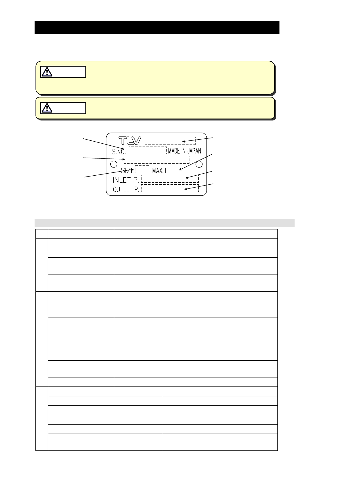
Serial Number
Valve No.*
Nominal Diameter
* Valve No. is displayed for products with options. This item is omitted from the nameplate when there are no
options.
Actuator Specifications
Actuator Model MC-GA2
Model
Maximum Operating
Temperature
Primary Pressure Range
Secondary Pressure
Adjustable Range
Power Source Voltage Free between 100 and 240 V AC (50/60 Hz)
Power Consumption With motor running: 75 VA max.
Insulation Resistance
500 V DC, 100 M min. between the power source
terminal and ground terminal
Withstand Voltage Between the power source terminal and ground terminal:
Power Source
1500 V AC, 1 min. or 1800 V AC, 1 second
Drive System Positional control by DC brushless motor
Operation Input
4 – 20 mA DC (input impedance 250 )
(Valve Opening)
Emergency Action Valve fully closed by an operation signal interruption.
When input power is cutoff: held at position just before
power cutoff
Time Rating Continuous
Operation
Thermal Protection Built-in overcurrent protection circuit
Time Required to Fully
Fully closed → fully open: Approx. 15 seconds
Open/Close
Manual Operation Possible with the power OFF
Allowable Ambient Temperature Range 0 to 50 °C (32 to 122 °F)
Allowable Ambient Humidity 10% to 90% RH (without dew)
Allowable altitude 2000m (6600 ft) max.
Vibration Resistance 0.5 G max.
Water Resistance Rain resistant (equivalent to IP54)
Environment
Material Motor cover: Aluminum
Main mounting plate: FC25 (cast iron)
172-65185A-08 (MC-COSR Multi-control Valve) 20 Nov 2014

CV Value
Size
(mm)
(in) (1/2) (3/4) (1) (11/4)(11/2)(2) (21/2) (3) (4) (5) (6)
Cv (US)
Cv (UK)
Kvs (DIN)
15 20 25 32 40 50 65 80 100 125 150
3.8 6.9 11.1 15.5 24.0 37.2 59.3 85.0 128
3.2 5.7 9.2 12.9 20.0 31.0 49.4 70.8 107
3.3 5.9 9.5 13.3 20.6 31.9 50.8 72.9 110
Acceptable Operating Range
Model MC-COSR-3 MC-COSR-16
5
180 275
150 229
154 236
Primary Pressure
Range
Secondary Pressure
Adjustable Range
(All conditions must
be met)
Minimum Adjustable
Flow Rate
0.1 – 0.3 MPaG
(15 – 45 psig)
0.01 – 0.05 MPaG
(1.5 – 7 psig)
5% or greater of
rated flow rate
0.2 – 1.6 MPaG
(30 – 250 psig)
Within 10 – 84% of the primary pressure
(Minimum adjustable pressure of
0.03 MPaG (5 psig))
Allowable pressure differential between
0.07 – 0.85 MPa (10 – 120 psi)
5% or greater of rated flow rate
NOTE:10% or greater of rated flow rate
for sizes 65 – 150 mm (2
1
/2 – 6 in)
(1 MPa = 10.197 kg/cm2)
172-65185A-08 (MC-COSR Multi-control Valve) 20 Nov 2014
Correct Usage of the MC-COSR Multi-control Valve
C
C
CAUTION
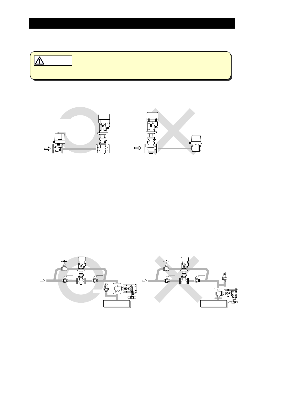
1. The MC-COSR should be operated only within its specifications.
Installing an ON / OFF Valve (Solenoid Valve or Motorized Valve)
2.
Install properly and DO NOT use this product outside the recommended
operating pressure, temperature and other specification ranges.
Improper use may result in such hazards as damage to the product or
malfunctions which may lead to serious accidents. Local regulations
may restrict the use of this product to below the conditions quoted.
MC-COSR
MC-COSR
6
Motorized
Valve
電動弁
Inlet Side
入口側
Outlet Side
出口側
Solenoid
電磁弁
Valve
If an on-off valve, such as a motorized valve, is required to stop supply of steam to the
steam-using equipment, install it at the inlet side of the MC-COSR. If a solenoid valve is
installed at the outlet of the reducing valve, its opening and closing will cause heavy
chattering and may lead to damage of the piston and main valve. (When the on-off
valve opens, the secondary pressure of the multi-control valve changes from zero to the
set pressure, passing through an area of the reducing ratio of less than 10:1, where
adjustment is impossible, chattering occurs momentarily.)
To save energy, install the on-off valve as near to the boiler as possible.
Note: To prevent water hammer, it is recommended that a slow-acting motorized on-off
valve be used. In particular, if a fast-acting on-off solenoid valve is used for
frequent temperature control, the potential water hammer effect can damage the
steam equipment and the multi-control valve.
3. Installing a Control Valve
Safety
安全弁
V ve al
ontrol
制御弁
MC-COSR
Safety
安全弁
Valve
Valve
MC-COSR
ontrol
制御弁
Valve
蒸気使用装置
Equipment
蒸気使用装置
Equipment
A control valve (i.e. for temperature control) installed between the MC-COSR and the
steam equipment (downstream of the MC-COSR) may raise the pressure between the MCCOSR and the control valve when the control valve is closed, depending on their spatial
relationship. Therefore, the control valve should be installed close to the steam equipment.
Also, a safety valve should be installed downstream of the control valve.
Note: When installing a safety valve to protect the steam equipment, be sure to install it
on the steam equipment or directly before the inlet of the steam equipment. If the
safety valve is installed between the MC-COSR and a control valve, an eventual
pressure rise could activate the safety valve.
172-65185A-08 (MC-COSR Multi-control Valve) 20 Nov 2014
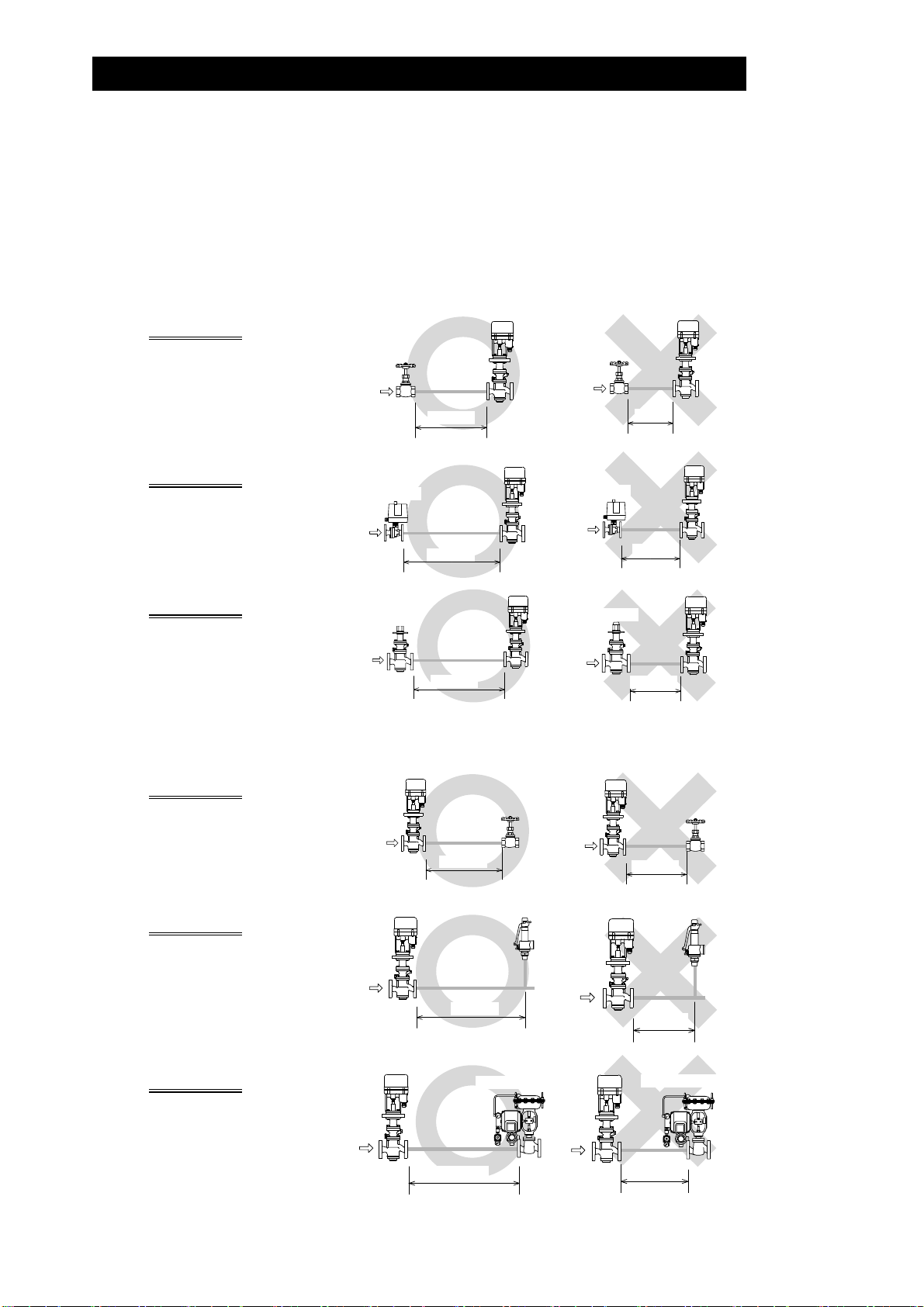
4. Recommended Straight Pipe Runs
L
m
y
In order to ensure stable steam flow, the piping upstream and downstream of the multicontrol valve must be straight runs. If a multi-control valve is installed either directly
before or after an elbow or control valve, unevenness in steam flow may result in
chattering and unstable pressure.
To ensure stable steam flow, it is recommended that the multi-control valve be installed
on straight runs of piping, as illustrated below.
7
Inlet (primary side) of the multi-control valve
Maintain a straight piping run
of 10 d or more
manual valve, a strainer or an
when a
Valve, strainer,
elbow, etc.
elbow, etc. is installed.
(Example: if nominal size is
25 mm (1 in), have 250 mm (10
in) or more)
Maintain a straight piping run
of 30 d or more
automated valve (on-off valve)
when an
Automatic
Valve
自動弁
is installed.
(Example: if nominal size is 25 m
(1 in), have 750 mm (30 in) or
more)
Maintain a straight piping run
of 30 d or more
when another
pressure reducing valve is
installed.
reduction)
(Example: if nominal size is
25 mm (1 in), have 750 mm (30
in) or more)
(Two-stage pressure
Pressure
減圧弁
Reducing Valve
Note: d = pipe diameter
10d以上
10 d or more
30d以上
30 d more or
30d以上
30 d or more
MC-COSR
MC-COSR
MC-COSR
e, strainer,
Valv
elbow, etc.
ess than
10d未満
Automatic
自動弁
Valve
Less than
30d未満
Pressure
Reducing Valve
減圧弁
Less than
10 d
30 d
30d未満
30 d
MC-COSR
MC-COSR
MC-COSR
Outlet (secondary side) of the multi-control valve
Maintain a straight piping run
of 15 d or more
when a
MC-COSR
manual valve, a strainer or an
elbow, etc. is installed.
(Example: if nominal size is
25 mm (1 in), have 375 mm (15
in) or more)
Maintain a straight piping run
of 30 d or more
when a
safety valve is installed.
(Example: if nominal size is
25 mm (1 in), have 750 mm (30
in) or more)
MC-COSR
15d以上
15 d or
30d以上
30
Maintain a straight piping run
of 30 d or more
when a
control valve or an automated
valve (on-off valve) is
installed.
(Example: if nominal size is
25 mm (1 in), have 750 mm (30
in) or more)
MC-COSR
30d以上
30 d or more
172-65185A-08 (MC-COSR Multi-control Valve) 20 Nov 2014
more
Safet
安全弁
Valve
ore d or m
Control or
制御弁または自動弁
Automated Valv
MC-COSR
Less than
15d未満
15 d
Safety
Less than
30d未満
安全弁MC-COSR
Valve
MC-COSR
e
Control or
制御弁または自動弁
Automated Valv
Less than
30d未満
30 d
e
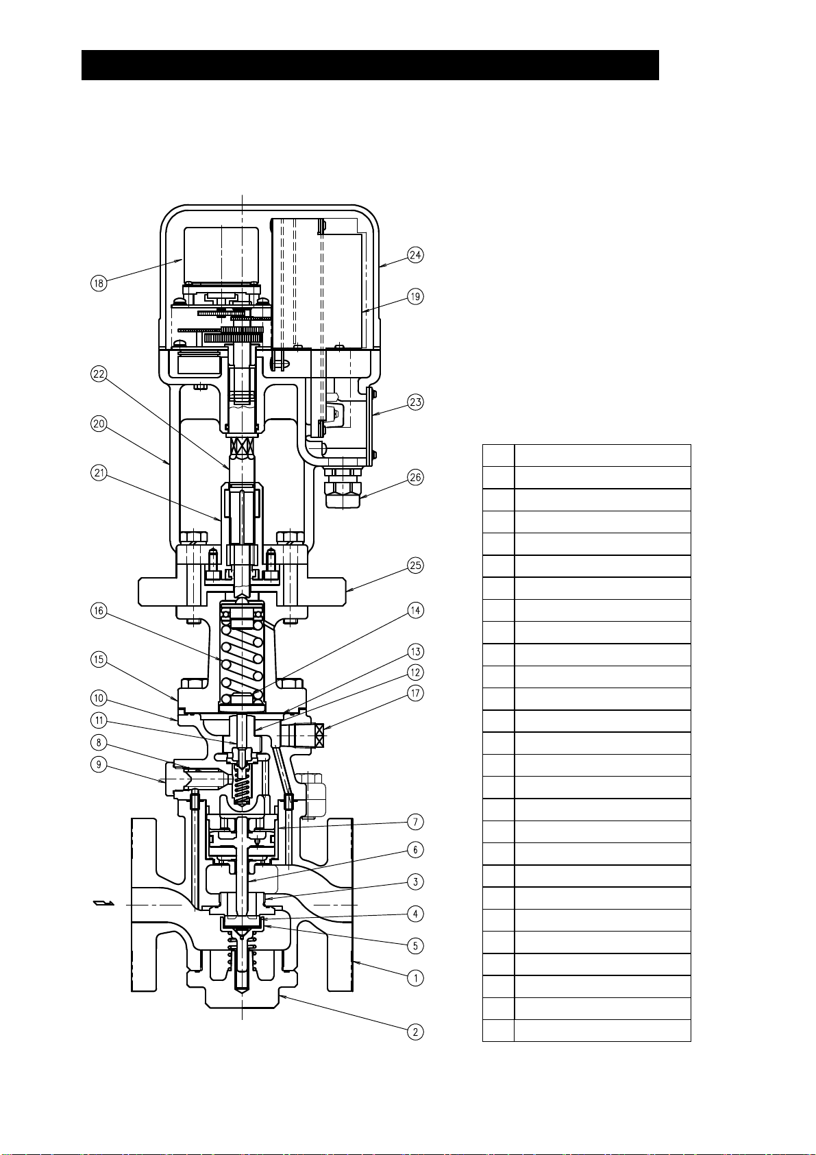
Configuration
15 – 25 mm (1/2 – 1 in)
8
No. Name
1 Main Body
2 (Main Body) Plug
3 Main Valve Seat
4 Main Valve
5 Main Valve Holder
6 Piston
7 Cylinder
8 Pilot Screen
9 Pilot Screen Holder
10 Pilot Body
11 Pilot Valve Stem
12 Pilot Valve Seat
13 Diaphragm
14 Diaphragm Support
15 Spring Housing
16 Coil Spring
17 Plug – Sensing Line Port
18 Motor Unit
19 Drive Unit
20 Mounting Plate
21 Adjustment Screw Guide
22 Adjustment Screw
23 Terminal Block Cover
24 Motor Cover
25 Insulation Plate
172-65185A-08 (MC-COSR Multi-control Valve) 20 Nov 2014
26 Cable Lock

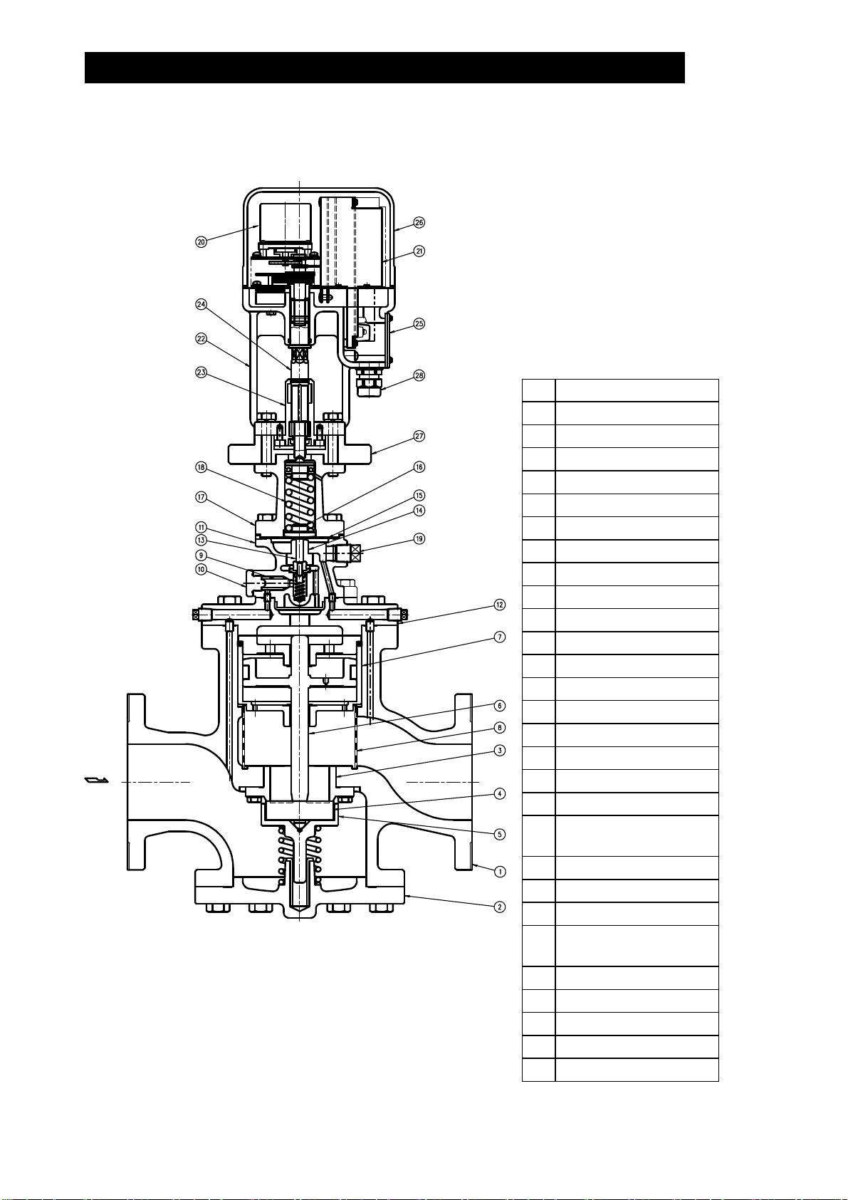
32 – 50 mm (11/4 – 2 in)
No. Name
1 Main Body
2 (Main Body) Cover
3 Main Valve Seat
4 Main Valve
5 Main Valve Holder
6 Piston
7 Cylinder
8 Pilot Screen
9 Pilot Screen Holder
10 Pilot Body
11 Pilot Valve Stem
12 Pilot Valve Seat
13 Diaphragm
14 Diaphragm Support
15 Spring Housing
16 Coil Spring
17 Plug – Sensing Line Port
18 Motor Unit
19 Drive Unit
20 Mounting Plate
21 Adjustment Screw Guide
22 Adjustment Screw
23 Terminal Block Cover
24 Motor Cover
25 Insulation Plate
26 Cable Lock
9
172-65185A-08 (MC-COSR Multi-control Valve) 20 Nov 2014
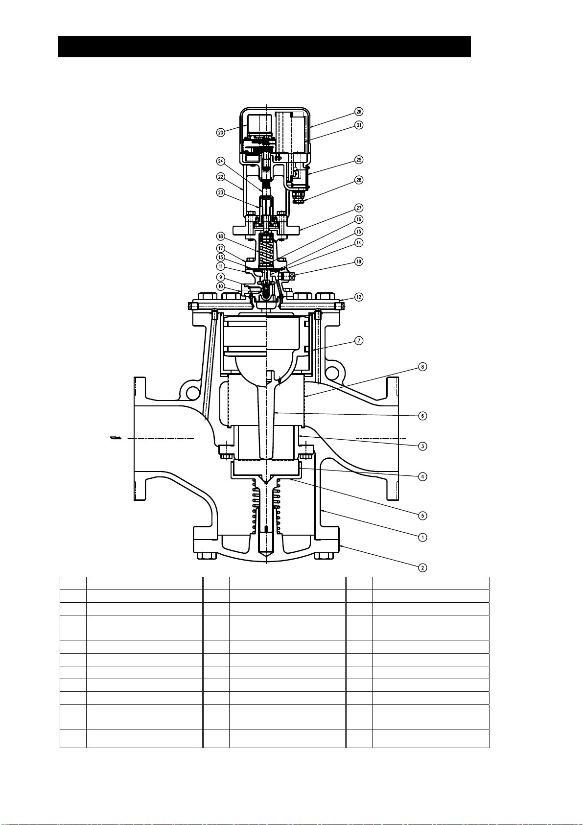
65 – 125 mm (21/2 – 5 in)
No. Name
1 Main Body
2 (Main Body) Cover
3 Main Valve Seat
4 Main Valve
5 Main Valve Holder
6 Piston
7 Cylinder
8 Silencer
9 Pilot Screen
10 Pilot Screen Holder
11 Pilot Body
12 Pilot Cover
13 Pilot Valve Stem
14 Pilot Valve Seat
15 Diaphragm
16 Diaphragm Support
17 Spring Housing
18 Coil Spring
Plug – Sensing Line
19
Port
20 Motor Unit
21 Drive Unit
22 Mounting Plate
Adjustment Screw
23
Guide
24 Adjustment Screw
25 Terminal Block Cover
26 Motor Cover
27 Insulation Plate
28 Cable Lock
10
172-65185A-08 (MC-COSR Multi-control Valve) 20 Nov 2014
150 mm (6 in)
11
No. Name No. Name No. Name
1 Main Body 11 Pilot Body 21 Drive Unit
2 (Main Body) Cover 12 Pilot Cover 22 Mounting Plate
3 Main Valve Seat 13 Pilot Valve Stem 23
4 Main Valve 14 Pilot Valve Seat 24 Adjustment Screw
5 Main Valve Holder 15 Diaphragm 25 Terminal Block Cover
6 Piston 16 Diaphragm Support 26 Motor Cover
7 Cylinder 17 Spring Housing 27 Insulation Plate
8 Silencer 18 Coil Spring 28 Cable Lock
9 Pilot Screen 19
10 Pilot Screen Holder 20 Motor Unit
Plug – Sensing Line
Port
172-65185A-08 (MC-COSR Multi-control Valve) 20 Nov 2014
Adjustment Screw
Guide

Installation
CAUTION
CAUTION
Install properly and DO NOT use this product outside the recommended
operating pressure, temperature and other specification ranges.
Improper use may result in such hazards as damage to the product or
malfunctions which may lead to serious accidents. Local regulations
may restrict the use of this product to below the conditions quoted.
Use hoisting equipment for heavy objects (weighing approximately
20 kg (44 lb) or more). Failure to do so may result in back strain or other
injury if the object should fall.
12
CAUTION
Take measures to prevent people from coming into direct contact with
product outlets. Failure to do so may result in burns or other injury from
the discharge of fluids.
Installation, inspection, maintenance, repairs, disassembly, adjustment and valve
opening/closing should be carried out only by trained maintenance personnel.
Installation Environment
Avoid installation in the following types of environments:
Locations with ambient temperatures above 50 °C (122 °F) or below 0 °C (32 °F)
Locations with ambient humidity above 90% RH and below 10% RH
Locations where corrosive gas is generated
Locations with heavy vibration or shock
Locations with high inductive interference or other factors that would have a
harmful effect on electrical circuitry
1. Blowdown
Before installing the MC-COSR, be
sure to blow down all piping
thoroughly. If this is not possible,
perform a blowdown using the
bypass valve.
Blowdown is especially important
for newly installed piping or after
the system has been shut down for
a long period of time.
2. Removing Seal and Cap
Before installation, be sure to remove all protective seals and caps
covering the product inlet and outlets. (Found in 2 locations.)
Open
開
Closed
閉閉
Blowdown with the Bypass Valve
MC-COSR
バイパス配管利用のブロー
Closed
3. Installation Angle
Install the MC-COSR vertically, so that the arrow mark on
the body points horizontally in the direction of steam flow.
Allowable inclination is 10 degrees in the fore-aft direction
and 15 degrees side to side in the plane perpendicular to
the steam flow line.
172-65185A-08 (MC-COSR Multi-control Valve) 20 Nov 2014
①②

4. Spacer Installation
If spacing adjustment is necessary
to accommodate installation, install
a spacer on the outlet flange. The
spacer should consist of a spacer,
gaskets, bolts and nuts. Fit gaskets
to both sides of the spacer between
the MC-COSR outlet and the pipe
flange. Fasten with bolts and nuts.
5. Piping Support
Install the MC-COSR,
paying attention to
avoid excessive load,
bending and vibration.
Support the inlet and
outlet pipes securely.
Correct
Spacer
スペーサ
Location
Incorrect
Spacer
Location
スペーサ
13
Unit: mm (in)
6. Maintenance Space
Leave sufficient space for maintenance,
inspection and repair.
(6)
(8)
(6)
(8) (8)
(4)
7. Pressure
(for pressure
control)
Pressure Sensor
圧力センサ
The length of piping
between the MCCOSR and pressure
sensor should be no
more than 5 m (17
ft). If the piping
distance is too great,
straight
MC-COSR
distance of 5m or less
pipe
直管長さ
15d以上
15 d or more
距離5m 以下
straight
5 d or
直管長さ
more
pressure loss and delay of pressure change along this distance will increase,
resulting in steam flowrate fluctuations. Steam fluctuations at the pressure
sensor may impair the stability of the pressure control. Ensure a straight piping
run of at least 15 d upstream and 5 d downstream from the pressure sensor.
pipe
5d以上
172-65185A-08 (MC-COSR Multi-control Valve) 20 Nov 2014

f
f
g
f
f
f
8. Piping Size / Diffuser
If the secondary steam flow
velocity is expected to be more
than 30 m/s (100 ft/s), install a
Diffuser
diffuser in order to keep the
ディフュー ザ
flow velocity below 30 m/s (100
ft/s). If the distance between
MC-COSR
the multi-control valve and the
steam equipment is great, a
possible drop in pressure
Straight-run
Piping Lengths:
=10 d or more =15 d or more
Upstream Downstream (d = pipe diameter)
直管部は上流側 10d 以上、下流側 15d 以上 (d:呼径)
should be taken into
consideration when selecting
the piping size.
MC-COSR
9.
Two-stage Pressure Reduction
Install a pressure reducing valve at the inlet side of MC-COSR whenever the
pressure cannot be reduced to the desired level with a single multi-control valve
due to operating range limitations, such as when the reduction ratio is greater
than 10:1.
14
パス弁
バイ
Bypass Valve
Pressure
Gauge
計
圧力
出口弁 口弁
Shutof
減圧弁
弁
入口
Shutoff
一次側
Inlet Side
Valve
Pressure
Inle de t Si
Pressure
Reducing
Valve
Bypass Valve
バイパス弁
圧力計
Gauge
一次側
Valve
Shutof
入口弁
Valve
バイパス弁
Bypass Valve
Shutof
MC-COSR
入口弁
Valve
Safety Valve (Relief Valve)
Shutof
出口弁
Valve
Safety Valve (Relief Valve)
出
Shutof
MC-COSR
安全弁(レリーフ弁)
Valve
圧力計
P ure Gauress
Ou Sidetlet
二次側
弁(レリーフ弁 )
安全
計
圧力
Pressure Gauge
二次側
Outlet Side
e
10. Accessories
Always install a shut-off valve, pressure gauge and bypass lines at both inlet and
outlet. Ball valves, which will not retain condensate, are recommended for inlet
and outlet shut-off valves. The bypass pipe should be at least ½ of the size of the
inlet (primary side) pipe. If installing a strainer before the multi-control valve,
horizontal installation with the basket in the same horizontal plane to the piping is
recommended in order to prevent condensate pooling.
Glove Valve
玉形弁
Ball Valve
MC-COSR
ボールバルブボールバルブ
Ball Valve
MC-COSR
172-65185A-08 (MC-COSR Multi-control Valve) 20 Nov 2014

11. External secondary pressure-sensing line (when required)
North American Models are factory prepared for external sensing.
An external sensing line MUST be installed.
DO NOT SUPPLY STEAM until all piping and a 10 mm (
3
/8 in) secondary
pressure sensing line with a slightly falling pitch have been properly installed.
Install a shutoff valve in the pressure sensing line for maintenance purposes.
15
CAUTION
Keep the shutoff valve open at all times during operation. If the shutoff
valve is closed, MC-COSR will fully open and PRIMARY PRESSURE WILL BE
SUPPLIED TO THE EQUIPMENT (see “Piping Example” on next page).
Non-North American Models
Factory-standard MC-COSR employs an internal secondary pressure-sensing
channel built into the body, saving the need to install an external pressuresensing line to detect the secondary pressure.
Installation of an external secondary pressure-sensing line involves closing the
internal pressure-sensing channel and installing a line from the sensing line port
to the point where pressure should be controlled. This can increase stability of
pressure control where steam loss in secondary piping and flowrate fluctuation is
high. In addition, the rated flowrate will be greater than an internal pressuresensing channel under the operational pressure reduction ratio of 2:1 or more.
Installation procedure
1) Loosen and remove the bolts that attach the pilot body to the main body (15 –
50 mm (
the pilot body.
2) Install the blind pin (optional) by first removing the connector from the main
body or pilot cover and then substituting the blind pin.
3) Re-install the pilot body and fasten the bolts evenly to the proper torque
(see Reassembly, page 29).
Remove the plug Rc(PT) ⅜ or NPT ⅜ and connect the secondary pressure
4)
sensing line.
5) Install the secondary pressure sensing line with a slightly falling pitch. The end
1
/2 – 2 in)) or the pilot cover (65 – 150 mm (21/2 – 6 in)) and remove
of the secondary pressure sensing line should be connected to the place on
the main piping where the pressure is to be sensed (see the piping example
on the next page). A shut-off valve and union should be installed in the
secondary pressure sensing line.
172-65185A-08 (MC-COSR Multi-control Valve) 20 Nov 2014

15 – 50 mm (1/2 – 2 in) 65 – 150 mm (21/2 – 6 in)
3
16
Pilot Valve Body
Main Body
Piping Example:
Plug (Rc(PT) ⅜ or NPT ⅜)
Hex Bolt
Secondary Pressure
Detection Port
Connector
Replace the factory-installed
connector with the blind pin
(optional)
Valve
バルブ
Pilot Body
Connector
10 mm (
(with a slightly falling pitch towards the
sensing point)
/8 in) Pressure Sensing Line
Secondary Pressure
Detection Port
Blind Pin
1 m
(3.3 ft)
MC-COSR
1m または15dの
or 15 d,
whichever is
大きい方
larger
15 d or more
15d以上
蒸気使用装置
Equipment
172-65185A-08 (MC-COSR Multi-control Valve) 20 Nov 2014

12. Internal sensing for North American models
All models except North American models are factory prepared for internal
sensing. When internal pressure sensing is required for North American models,
please contact the nearest TLV representative to request both a connector, which
must be installed in place of the blind pin, and a threaded secondary pressure
sensing plug.* Follow the connector installation procedure shown below:
1) Loosen and remove the four (4) bolts that attach the pilot body to the main
body (15 – 50 mm (
and remove the pilot valve body.
2) Install the connector by first removing the blind pin from the secondary side of
the main body or pilot cover and then substituting the connector.
3) Re-install the pilot body and fasten the four (4) bolts evenly.
Consult page 30 in this manual for torque requirements of these bolts.
4) If a secondary pressure sensing pipe has previously been installed, remove it
and be certain to install the threaded secondary pressure sensing line plug in
its place.
*Internal sensing should not be used when 15 mm (
COS-16 will be used below 0.3 MPaG (45 psig) and 0.1 MPaG (15 psig)
respectively, and below 50% of primary pressure.
1
/2 – 2 in)) or the pilot cover (65 – 150 mm (21/2 – 6 in)),
Blind Pin
Connector
1
/2 in) and 20 mm (3/4 in) MC-
17
172-65185A-08 (MC-COSR Multi-control Valve) 20 Nov 2014

Wiring
Ground
Wiring Notes
Background electromagnetic noise that has no effect on analog equipment may
cause digital equipment to malfunction or fail. To prevent adverse effects from
electro-magnetic (EM) interference, carefully follow the wiring instructions below:
1. Power Source
1) If there is EM noise from the power source, a filter should be used. To prevent
interference, do not bundle the EM filter's power source input and output lines
together.
2) Although there is a built-in fuse in the controller, there is no power switch. It is
required that a power switch be installed on an external circuit near the main
unit. Do not install a power switch between the EM filter and the valve, as this
will reduce the effectiveness of the filter.
EM Signal Filter
Power Switch
Power Supply
Drive
Section
Terminal
Block
18
3) A power cable is not included with the unit. See “Wiring Instructions”.
4) Install an overcurrent protection device on the power supply lines (both poles)
to prevent overcurrent.
Recommended rating of the device: 250V/2A, Delay type
2. Input/Output Signal Lines for Valve Operation
1) Use shielded cables for the I/O signal lines.
Connect the shielded cables to the receiver's shield terminal.
2) Separate the I/O signal cables from power cables, drive cables, and EM noisegenerating equipment. Do not insert I/O signal cables in common piping or
ducts with aforementioned cables.
Drive
Section
Terminal
Block
3. Ground
Controller
Terminal
Block
Shield
Shielded Cable
1) Be sure to ground the MC-COSR and the controller.
2) Use a one-point ground at the same point as the ground for the controller to be
used with the valve. Do not use extension wiring. Failure to ground the valve as
specified may cause it to malfunction.
3) For the ground terminal, use a flexible copper wire, at least 2 mm
Ground with a ground resistance of 100 or less (Class 3 ground).
Power Supply
Controller
Terminal
Block
Drive
Section
Terminal
Block
Power Supply
2
(0.003 in2).
Ground
172-65185A-08 (MC-COSR Multi-control Valve) 20 Nov 2014

Wiring Instructions
r
y
(
)
(
)
CAUTION
CAUTION
Drive Section Terminal Box
Make sure the power supply switch is OFF before carrying out work on
the wiring or inspections involving disassembly.
If such work is carried out with the power on, there is a danger that
equipment may malfunction or electric shock may occur, leading to
injury or other accidents.
Make sure that wiring work requiring a special license is carried out by
qualified personnel.If carried out by unqualified personnel, overheating
or short circuits leading to injury, fires, damage or other accidents may
occur.
19
MC-COSR
Terminal
Box
Drive Section T
Power Suppl
100 – 240 V AC
erminal Block
Controlle
Shield
Shield Cable
Terminal Block
When making a connection to the terminal block, use crimp-style jacks (for M4) with
insulation sleeves.
6.6 mm
(0.26 in)
4.3 mm
0.17 in
6.3 mm
0.24 in
(0.24 in)
9.0 mm
(0.35 in)
(0.35 in)
Recommended Cable Specifications
Cable Specifications
Actuator
Terminal No.
Power Source 1, 2 1.25 (0.002) 16
GND
Valve Operation
Signals
* (American Wire Gauge)
3 (shield),
4 (), 5 ()
Minimum
Cross Section
2
(in2)
mm
Maximum Wire
Gauge No.
(AWG)*
Cable Type
Cabtyre cable
2.00 (0.003) 14
0.75 (0.001) 18
172-65185A-08 (MC-COSR Multi-control Valve) 20 Nov 2014
2 conductor
shielded cable

20
Setting the Valve Coefficient
About the Valve Coefficient
1. Features of the MC-COSR
The MC-COSR valve has a pressure self-adjustment function with the following
features:
1) Maintains the secondary steam pressure at a stable level even when the primary
2) Maintains the interrelationship between the secondary steam pressure and the
2. What is the valve coefficient?
The valve coefficient expresses the relationship between the secondary steam
pressure and the stroke position of the pressure adjustment screw on the MC-COSR.
There are five different valve coefficients; labeled A through E. Valve coefficients are
derived by TLV for each valve through tests before shipment from the factory. They
are stamped on the valve coefficient nameplate label attached to the valve and a
removable label to be utilized for putting the valve coefficients into the controller.
Combining the MC-COSR and the TLV SC-F70 or SP-F70 Controller
The SC-F70 digital indicator controller and SP-F70 programmable indicator controller
made by TLV use proprietary control algorithms designed to take full advantage of
MC-COSR’s potential. Examples include MC-COSR's high stability, resistance to
external disturbances and its precise response to setting changes. Combining the
MC-COSR with these controllers provides a level of control not possible with other
conventional control valves and PID controllers.
Setting the Valve Coefficient
In order to fully utilize the MC-COSR,
be sure to provide the SC-F70 or
SP-F70 controller with the MC-COSR
valve coefficient.
Failure to do so will make AUTO
mode operation impossible and an
error message will be displayed on
the controller.
steam pressure and secondary steam flow fluctuate.
stroke position of the pressure adjustment screw determined by the drive section.
Valve Coefficient
Label
172-65185A-08 (MC-COSR Multi-control Valve) 20 Nov 2014
Valve Coefficient
Nameplate

Operation
p
CAUTION
Procedure
1. Operational check
Before turning ON the power, check to make sure all cable connections are correct.
1)
2) To close the valve, send an operation signal value of 0% (4 mA) or less from
the controller to MC-COSR and maintain that value.
3) Turn ON the power to the actuator.
4) The MC-COSR valve should be closed.
• Check to make sure no steam is flowing
to the secondary side.
• Check to see whether there is a slight
back and forth motion of the pressure
adjustment screw. If there is, this may
be due to EM interference.
When using this product, NEVER stand close to, or leave tools anywhere
near moving parts, such as the ajustment screw. Contact with moving
parts or objects becoming caught in moving parts could lead to injury or
damage or other accidents.
Steam
21
5) On the controller, increase the value of the operation signal
to the MC-COSR.
• Check to make sure that, when viewed from above, the
Adjustment
Screw
adjustment screw in the drive section is rotating clockwise
while moving downward.
• Check to make sure that steam begins to flow to the
secondary side of the MC-COSR and the secondary steam
pressure rises.
Clockwise &
Down
6) At the same time, begin reducing the value of the operation
signal to the MC-COSR on the controller.
• Check to make sure that, when viewed from above, the
Adjustment
Screw
adjustment screw in the drive section is rotating counterclockwise while moving upward.
• Check to make sure that the steam pressure on the
MC-COSR secondary side decreases.
Counter-
clockwise
& U
7) In the event that an abnormality is detected in operation when checking with the
above procedure, consult the Troubleshooting chapter in this manual and take the
appropriate remedial steps.
2. AUTO operation
Enter target settings and other necessary parameters into the controller and start
AUTO operation. The drive section of the MC-COSR will begin operating
automatically in response to the operation signals from the controller.
172-65185A-08 (MC-COSR Multi-control Valve) 20 Nov 2014

In the Event of a Power Outage
CAUTION
1. When the power to the drive section has been cut off:
The drive section will stop at the position it was at just before the power was cut off.
As a result, the pressure of the steam supplied to the equipment will be maintained
at the pressure just before the power went off.
If the supply of steam needs to be stopped during a power outage, install an ONOFF valve on the primary side of the MC-COSR.
2. When only the operation signal to the actuator has been cut off:
The actuator will rotate counter-clockwise to raise the adjustment screw to the 0%
or lower position. As a result, the multi-control valve will close, cutting off the
supply of steam to the secondary side.
3. When power is restored:
The adjustment screw will return to the position specified by the operation signals
from the controller.
Manual Operation
Make sure the power supply switch is OFF before carrying out work on
the wiring or inspections involving disassembly.
If such work is carried out with the power on, there is a danger that
equipment may malfunction or electric shock may occur, leading to
injury or other accidents.
22
1) Before beginning manual operation, turn OFF the power to the drive section.
2) Using a wrench as shown in the figure below, slowly turn the adjustment screw. Be
careful not to apply too much force. (A torque of about 7 Nm (5 lbf·ft) will be
required to turn the adjustment screw with the wrench.)
3) Turning the adjustment screw clockwise when viewed from above will INCREASE
the secondary steam pressure.
4) Turning the pressure adjustment screw counter-clockwise when viewed from
above will DECREASE the secondary steam pressure.
Counter-clockw
Decrease Pressure
Clockwise to
Increase Pressure
ise to
172-65185A-08 (MC-COSR Multi-control Valve) 20 Nov 2014

Inspection and Maintenance
CAUTION
Take measures to prevent people from coming into direct contact with
product outlets. Failure to do so may result in burns or other injury from
the discharge of fluids.
23
CAUTION
CAUTION
Operational Check
Be sure to use only the recommended components when repairing the
product, and NEVER attempt to modify the product in any way. Failure to
observe these precautions may result in damage to the product or burns
or other injury due to malfunction or the discharge of fluids.
Make sure the external power supply switch is OFF before carrying out
work on the wiring or inspections involving disassembly.
If such work is carried out with the power on, there is a danger that
equipment may malfunction or electric shock may occur, leading to
injury or other accidents.
To ensure long service life of the MC-COSR, the following inspection and
maintenance should be performed regularly.
Part Inspection and Maintenance Frequency
Screens
(Pilot)
Disassemble and clean annually.
If there is substantial blockage, install a strainer (60
mesh or finer) ahead of the MC-COSR.
Main Valve, Main
Valve Seat, Pilot Valve
Replace after approximately 15,000 hours.
If there is chattering or dirt, premature wear may result.
and Pilot Valve Seat
Piston Ring Replace after approximately 8,000 hours.
If there is chattering or if scale build-up is severe,
premature wear may result.
Piston Replace after approximately 30,000 hours.
If hunting or chattering takes place, premature wear may
result.
Diaphragm Replace after approximately 30,000 hours.
If hunting or chattering takes place, cracks or fatigue
may develop in a short period of time.
Bearing
(in spring housing)
Replace after approximately 8,000 hours.
If the ambient temperature is high, premature wear may
result.
172-65185A-08 (MC-COSR Multi-control Valve) 20 Nov 2014

Disassembly
r
CAUTION
Use hoisting equipment for heavy objects (weighing approximately
20 kg (44 lb) or more). Failure to do so may result in back strain or other
injury if the object should fall.
24
CAUTION
When disassembling or removing the product, wait until the internal
pressure equals atmospheric pressure and the surface of the product
has cooled to room temperature. Disassembling or removing the
product when it is hot or under pressure may lead to discharge of fluids,
causing burns, other injuries or damage.
It is a recommended practice to dismantle and inspect the MC-COSR once a year for
preventive maintenance purposes. It is especially important to do so immediately
after the initial run of a new line or before or after equipment such as a heater is out
of service for a long period of time.
(Installation, inspection, maintenance, repairs, disassembly, adjustment and valve
opening/closing should be carried out only by trained maintenance personnel.)
Before Dissassembly
Remove all steam from the piping (both upstream and downstream). Set the value of
the valve operation signal from the controller to the MC-COSR to 0% (4mA) or less.
The drive section will operate in response to the valve operation signal, with the
adjustment screw moving counterclockwise and up to close the valve. Wait for the
body to cool before attempting to remove the MC-COSR from the line. Turn OFF the
power to both the drive section and the valve operation signal (controller) and
disconnect the cables. Then remove inlet and outlet flange retaining bolts and nuts to
permit removal of the MC-COSR. Secure the MC-COSR in a vise to perform the
inspection.
Disassembling the Adjustment Section
Loosen the adjustment screw completely and remove
the bolts from the spring housing. Grasp the mounting
plate and lift the spring housing straight up and off.
Having removed the spring housing, you will see the
diaphragm retainer, coil spring, bearing and spring retainer.
Check to make sure there is no dirt, etc. inside the
spring housing, and check for seizure or any damaged
screw threads. Then, using a wrench, turn the
adjustment screw back and forth. Check to make sure
that it turns smoothly. A slight torque is necessary since
the motor has a rotational load. If the adjustment screw
does not rotate smoothly, contact TLV immediately.
Note: Do not remove the drive section cover. The
drive section, which contains precision
electronic components, is maintenance-free.
Bolt
Spring
H
ousing
Spring
Retaine
Bearing
Coil
Spring
Diaphragm
Support
Adjustment
Screw
Mounting
Plate
172-65185A-08 (MC-COSR Multi-control Valve) 20 Nov 2014

25
Disassembling the Pilot Section
The diaphragm is removed by utilizing the notch in the pilot body. Loosen and
remove the pilot valve seat with a box wrench. Pick up the pilot valve and the pilot
valve spring with a pair of tweezers. Loosen and remove the pilot screen holder to
remove the pilot screen.
Check for any fault on the seat of the pilot valve, flaws on the gaskets, and clogging
of the pilot screen. Check for deformation, corrosion or faults on the diaphragm. The
diaphragm should be convex (open downward), with the printed UP mark on the top.
15 – 50 mm (1/2 – 2 in)
Diaphragm
Upper Pilot Body Gasket
Pilot Body
Bolt
Pilot Valve Seat
(with gasket)
Notch
65 – 150 mm (2
Upper Pilot Body Gasket
Pilot Body
Notch
Pilot Screen
Pilot Screen Holder
(with gasket)
Pilot Screen
Holder (with
gasket
1
/2 – 6 in)
Pilot Screen
)
Connector
Bolt
Pilot Valve Stem
Pilot Valve
Pilot Valve
Spring
Diaphragm
Pilot Valve Seat
(with gasket)
Pilot Valve Stem
Pilot Cover
Lower Pilot
Body Gasket
Pilot Valve
Pilot Valve
Spring
172-65185A-08 (MC-COSR Multi-control Valve) 20 Nov 2014

26
Disassembling the Main Valve Section
Remove the pilot body after loosening and removing the bolts. During this process,
pay attention not to lose the two connectors. Remove the piston and the cylinder
from the main body. Then remove the piston ring and the tension ring from the
piston.
Note: Do not apply too much force when removing the piston ring and tension ring.
Inspect the interior of the cylinder, the exterior of the piston rings, the small hole on
the piston and the gaskets for any fault or abnormality.
15 – 50mm (
Piston Ring
Tension Ring
Cylinder (with gasket)
Lower Pilot Body Gasket
1
/2 – 2 in)
62 – 125 mm (2
1
/4 – 5 in)
Piston Retainer
Piston
Connector
Bolt
150 mm (6 in)
Piston Ring
Tension Ring
Cylinder (with gasket)
Pilot Cover Gasket
Silencer
Piston Retainer
Piston
Connector
Bolt
Seal Ring
172-65185A-08 (MC-COSR Multi-control Valve) 20 Nov 2014

27
r
/ –
)
)
)
Disassembling the Main Valve and Cover Sections
Loosen the bolts and remove the cover permits removal of the main valve, main
valve holders and main valve spring. Remove the main valve seat from the main
body with a box wrench.
Check for damage on the seating and sliding surfaces of the main valve and the
gaskets.
[At startup following shutdown for a long period, always blow down the piston section
of the main body through the plug if equipped.]
15 – 25 mm (1/2 – 1 in)
Cove
Gasket
Main Body
32 – 50 mm (11/4 – 2 in)
65 – 150 mm (2
1
6 in
Cover
Gasket
Bolt
Main Body
Main Body
A
B
C
D
Main Valve Section
(15 – 25 mm)
1
(
/2 – 1 in)
A
B
C
D
Plug (Option
Main Valve Section
(32 – 50 mm)
1
(1
/4 – 2 in)
Plug (Option
/2 – 6 in)
A: Main Valve Seat (with gasket)
B: Main Valve
C: Main Valve Holder
Cover
Gasket
Bolt
A
B
C
D
E
Main Valve Section
(65 – 150 mm)
1
(2
D: Main Valve Spring
E: Bolt
172-65185A-08 (MC-COSR Multi-control Valve) 20 Nov 2014

Cleaning
After inspection and removal of any abnormality, clean and reassemble the parts.
The following parts will require cleaning before reassembly:
Pilot Screen Piston Ring
Main Valve Seat Cylinder
Main Valve Pilot Valve
Piston Pilot Valve Seat
It is permissible to clean using water, however cleaning with a mild detergent is
recommended for more effective cleaning.
Exploded View
NOTE: The shape of individual parts may vary depending on the model size.
Drive Section
Adjustment Section
Pilot Section
Main Body /
Main Valve Section
Cover Section
28
172-65185A-08 (MC-COSR Multi-control Valve) 20 Nov 2014

29
Reassembly
Assemble the unit using the same procedure as used for disassembling it; but in
reverse order. Observe the following precautions:
1. The PTFE gaskets may be re-used if free from fault, crushing or deformation.
2. Apply anti-seize to the threaded portion of screws and bolts and adjustment screw.
Apply a small amount of anti-seize to the threads of the main valve seat, pilot
valve seat and pilot screen holder. Apply anti-seize carefully to ensure it does not
come into contact with other parts.
3. Fasten the bolts one at a time in an alternating diagonal pattern to provide uniform
seating.
4. After assembly, make sure that the piston and the pilot valve operate smoothly
without binding.
Assembling the Piston Ring
Piston Ring
Tension Ring
1) Fit the piston ring to the outside
2) The ring gaps should be opposite
Ring Gaps
Standard fastening torque and the distance across flats to be used are as follows:
5.
Part
mm (in) mm (in) N·m (lbf·ft)
Bolt for Mounting
Plate/Spring Housing
Bolt for Spring
Housing/Pilot Body
Pilot Valve Seat All 19 (3/4) 70 (51)
Pilot Screen Holder All 24 (15/16) 40 (29)
Bolt for Pilot
Body/Main Body
Bolt for Pilot
Body/Pilot Cover
Bolt for Pilot
Cover/Main Body
15 – 40 (1/2 – 11/2) 17 (21/32) 60 (44)
50 (2) 19 (
65 - 150 (2
65 - 80 (21/2 – 3) 19 (3/4) 70 (51)
100, 125 (4, 5) 24 (15/16) 150 (110)
150 (6) 36 (1
15, 20 (1/2 – 3/4) 36 (17/16) 100 (73)
Main Valve Seat
25 (1) 41 (15/8) 125 (92)
32, 40 (11/4, 11/2) 60 (23/8) 250 (185)
50 (2) 70 (2
Bolt for Main Valve
Seat
(Main Body) Plug
65, 80 (21/2, 3) 13 (1/2) 30 (22)
100, 125 (4, 5) 17 (21/32) 40 (29)
150 (6) 22 (
15 – 20 (1/2 – 3/4) 41 (15/8) 250 (185)
25 (1) 46 (1
32 – 40 (11/4 – 11/2) 17 (21/32) 60 (44)
Bolt for Cover / Main
Body
50 – 80 (2 - 3) 19 (3/4) 70 (51)
100, 125 (4, 5) 24 (15/16) 150 (110)
150 (6) 36 (1
Note: - If a torque greater than that recommended is applied, the MC-COSR or (1 Nm 10 kgcm)
components may be damaged.
- If drawings or other special documentation were supplied for the product, any torque given there
takes precedence over values shown here.
Size
All 17 (
All 17 (
1
/2 – 6) 17 (21/32) 60 (44)
of the tension ring.
each other.
Width Across
Flats
21
/32) 30 (22)
21
/32) 40 (29)
3
/4) 70 (51)
7
/16) 300 (220)
3
/4) 300 (220)
7
/8) 70 (51)
13
/16) 350 (260)
7
/16) 300 (220)
Tightening
Torque
172-65185A-08 (MC-COSR Multi-control Valve) 20 Nov 2014

30
p
Troubleshooting
CAUTION
CAUTION
This product is shipped after stringent checks and inspection and should perform its
intended function for a long period of time without failure. However, should there be
any problem encountered in the operation of the MC-COSR, identify where the
trouble occurs and consult the troubleshooting guide below. When a problem arises,
the trouble may lie in the MC-COSR drive section, pressure reducing valve section
or the controller.
When disassembling or removing the product, wait until the internal
pressure equals atmospheric pressure and the surface of the product
has cooled to room temperature. Disassembling or removing the
product when it is hot or under pressure may lead to discharge of fluids,
causing burns, other injuries or damage.
When using this product, NEVER stand close to, or leave tools anywhere
near moving parts, such as the ajustment screw. Contact with moving
parts or objects becoming caught in moving parts could lead to injury or
damage or other accidents.
Identifying Problem Areas
1. Set the operation mode to MANUAL (MAN) on the controller connected to the
MC-COSR. This is to enable the operation signal to the drive section to be
changed to any value.
2. Set the control output on the controller to any value. Check to make sure that the
pressure adjustment screw in the drive section is stopped completely and is not
hunting (the secondary steam pressure is stabilized).
3.
Increase the control output on the controller. Check to make
sure that, as viewed from above, the pressure adjustment
screw rotates clockwise while moving downward, and that
the secondary steam pressure increases.
4. In the same manner, decrease the control output on the
controller. Check to make sure that, as viewed from above,
the pressure adjustment screw rotates counterclockwise
while moving upward, and that the secondary steam
pressure decreases.
5. If the process in steps 2. – 4. above reveals that:
• The pressure adjustment screw is operating normally but
the secondary steam pressure does not change, then see the Pressure
Reducing Valve Troubleshooting section.
• The pressure adjustment screw does not rotate, then go on to the next step.
Adjustment
Screw
Clockwise &
Down
Adjustment
Screw
Counter-
clockwise
& U
172-65185A-08 (MC-COSR Multi-control Valve) 20 Nov 2014

31
6. Check to see whether the proper line voltage and control signals are being input to
the terminals in the drive section terminal box. With the proper wiring, the values
should be within the following ranges:
• Line voltage (between terminals 1 and 2): If the value is outside the range of 90 -
264 V AC, enter the proper line voltage.
• Control signal (between terminals 4 and
5): 0.8 – 5.2 V DC.
Note: When the control signal from the
controller is:
0% – the value should be
50% – the value should be
100% – the value should be
Points in between those above will vary
approx. 1 V DC
approx. 3 V DC
approx. 5 V DC
proportionally.
MC-COSR
Terminal Box
Drive Section Terminal Block
Power Supply
100 - 240 V AC
Controller Terminal Block
SC-F70/SP-F70
If the value is outside this range, check for disconnected wiring or controller
malfunction. If the voltage is correct but the drive section does still not rotate,
there may be a malfunction in the drive unit. Refer to “Drive Section
Troubleshooting” and take appropriate measures.
7.
Turn OFF the power to the drive section.
8. Using a wrench, turn the adjustment
screw slowly. Be careful not to apply
excessive force.
9.
If the adjustment screw cannot be turned
by hand or if it requires more than 10
Nm (7 lbfft) torque to do so, contact a
TLV serviceperson.
Counterclockw
–
Pressure
Decreases
ise
10. Check to make sure that the secondary
steam pressure increases when, as seen
from above, the adjustment screw has
been turned clockwise.
Clockwise
–
Pressure
Increases
11. Check to make sure that the secondary
steam pressure decreases when, as
seen from above, the adjustment screw
has been turned counterclockwise.
12.
If the secondary steam pressure does not change in steps 10. and 11. above, see
the Pressure Reducing Valve Troubleshooting section.
Shielded Cable
172-65185A-08 (MC-COSR Multi-control Valve) 20 Nov 2014

32
Pressure Reducing Valve Troubleshooting
Problems are classified as follows:
1. The secondary pressure does not increase.
2. The secondary pressure cannot be adjusted or increases abnormally.
3. Hunting occurs (fluctuation of the secondary pressure).
4. Chattering occurs (a heavy mechanical noise).
5. Abnormal noises.
Major causes for the above problems are usage under non-specified conditions (out
of specification), insufficient pressure or flow rate, and clogs by dirt and scale.
Be sure to check for these causes.
To ensure performance for a long period of time, it is recommended that the Safety
Considerations and Adjustment sections be reviewed.
Troubleshooting Chart
Problem Symptom Cause Remedy
Secondary
pressure
does not
rise
Secondary
pressure
cannot be
adjusted or
increases
abnormally
The body is not
warm
The body is warm,
but the pressure
does not increase
The motor is not
turning over
Adjustment is
difficult, and set
pressure varies
No steam is being supplied
or the inlet valve is closed
The screens or strainer are
clogged
The controller is
malfunctioning
The pilot screen is clogged Clean
There is insufficient steam
flow
The piston is clogged with
dirt
The piston ring is worn Replace with a new
The small hole on the piston
is clogged
There is a dirt build-up on the
sliding surfaces of the pilot
valve, piston or main valve
Flow rate exceeds rated
flow rate
The adjustment screw has
seized
The diaphragm is distorted
or damaged
There is fluctuation in steam
consumption
The selected model is
inappropriate for the service
conditions (specifications)
Troubleshooting continued on next page
Check upstream steam
pipeline
Clean or blow down
Check, repair
Check the flow; replace
the MC-COSR if necessary
Clean; check the piston
ring
piston ring
Clean
Clean
Check the flow rate;
replace with a larger size
Replace with a new
adjustment screw
Replace with a new
diaphragm
Check flow rate; replace
the MC-COSR if necessary
Check the model
selection; replace the
MC-COSR if necessary
172-65185A-08 (MC-COSR Multi-control Valve) 20 Nov 2014

Troubleshooting Chart (continued)
Problem Symptom Cause Remedy
Secondary
pressure
cannot be
adjusted or
increases
abnormally
(continued)
Hunting or
chattering
occurs
Abnormal
noises
Upon closing
secondary side
valves, secondary
pressure abruptly
rises as high as
primary pressure
Occurs at low
steam demand
Hunting never
stops
Chattering never
stops
Makes a highpitched noise
The bypass valve is leaking Check; clean; replace
with a new valve if
necessary
The pilot valve seat or main
valve seat is damaged
There is a build-up of dirt on
the pilot valve seat or main
valve seat
It is being operated below
the lower flow rate limit
There is too high a reduction
ratio (operated at below 10%
of the primary pressure)
The selected model is
inappropriate for the service
conditions (specifications)
Condensate is contained check the piping
The selected model is
inappropriate for the service
conditions (specifications)
There is too high a
reduction ratio, the flow is
too great, or there is a highspeed open / close valve
nearby
Replace damaged parts
with new
Clean; align; replace if
necessary
Check the volume of
steam supply, replace
with a smaller diameter valve
Use a two-stage
reduction arrangement
Check the model
selection, replace the
MC-COSR if necessary
Check the model
selection, replace the
MC-COSR if necessary
Use two-stage reduction
Check the flow rate, use
a larger size valve
Install the valve as far
away as possible
33
172-65185A-08 (MC-COSR Multi-control Valve) 20 Nov 2014

34
Drive Section Troubleshooting
The drive section has a built-in microcomputer that has a self-diagnosis function of the
malfunction of the drive section.
Identify the cause of faulty by following procedures shown below.
1. Turn OFF the power (supplying) to the drive section.
2. Remove the motor cover (blue housing) of the drive section.
3. Confirm the position of the 4 LEDs (LE1 – 4) and the switch (PS1) mounted on
the board from the terminal block side.
4. Turn ON the power supply to the drive section, being careful not to be
electrocuted or cause a short out since the electrical circuit is exposed.
5. Press the PS1 switch. Confirm the lighting status of the 4 LEDs. Different LEDs
light up depending on the malfunction. Refer to the table on the next page and
take proper measures.
172-65185A-08 (MC-COSR Multi-control Valve) 20 Nov 2014

Malfunctions and Countermeasures
○:OFF ●:ON
LE 4, 3, 2, 1 Malfunction Details Performance of the
actuator when
abnormality occurs
○○○○ No malfunction is
detected (All LEDs
are normally OFF)
○○○● Operation signal
input error
●○○○ Temperature in the
actuator is
abnormal
○○●● Motor is
overloaded
○●○● Low motor load
(reducer gear wear,
motor slippage)
●○○● Potentiometer
signal error
Continuous operation
Continuous operation Operation input signal is
Continuous operation Make sure that the
Motor shuts down,
then keep rebooting
after a few seconds.
Continuous operation Possibility of abnormal wear
Stops when
malfunction occurs
●○●○ Initialization error Stops when
●●○○ E
2
PROM Store
Error
○●●● Motor drive power
voltage is
abnormal
malfunction occurs
Stops when
malfunction occurs
Continuous
operation
●○●● CPU Error Stops when
●●●○ External clock
stops
malfunction occurs
Continuous operation
using internal clock
●●●● Mode Setting Error Stops
○○●○ (spare) Continuous operation
○●○○ (spare) Continuous operation
○●●○ (spare) Continuous operation
●●○● (spare) Continuous operation
35
Remedy
abnormal.
Make sure that there is no
abnormality with the
controller and the cable for
the operation input signal.
temperature around the
drive section is within the
specification range (0 to
50 °C (32 – 122 F°).
Motor is abnormally
overloaded. Contact
TLV.
of the gear in the reducer.
Contact TLV.
Potentiometer is
abnormal. Contact TLV.
If the same phenomenon
occurs after switching the
power OFF and ON, contact
TLV.
Possible abnormality of
the power supply circuit is
considered. Contact TLV.
If the same phenomenon
occurs after switching the
power OFF and ON, contact
TLV.
Possible abnormality of
the internal circuit.
Contact TLV.
172-65185A-08 (MC-COSR Multi-control Valve) 20 Nov 2014

f
A
A
W
EXPRESS LIMITED WARRANTY
Subject to the limitations set forth below, TLV Corporation, a North Carolina corporation
(“TLV”) warrants that products which are sold by it or TLV International, Inc., a Japanese
corporation (“TII”), which products (the “Products”) are designed and manufactured by
TLV Co., Ltd., a Japanese corporation (“TLVJ”), conform to the specifications published
by TLV for the corresponding part numbers (the “Specifications”) and are free from
defective workmanship and materials. With regard to products or components
manufactured by unrelated third parties (the “Components”), TLV provides no warranty
other than the warranty from the third party manufacturer(s).
Exceptions To Warranty
This warranty does not cover defects or failures caused by:
1. improper shipping, installation, use, handling, etc., by other than TLV or service
representatives authorized by TLV; or
2. dirt, scale or rust, etc.; or
3. improper disassembly and reassembly, or inadequate inspection and maintenance
by other than TLV or service representatives authorized by TLV; or
4. disasters or forces of nature; or
5. abuse, abnormal use, accidents or any other cause beyond the control of TLV; or
6. improper storage, maintenance or repair; or
7. operation of the Products not in accordance with instructions issued with the
Products or with accepted industry practices; or
8. use for a purpose or in a manner for which the Products were not intended; or
9. use of the Products in a manner inconsistent with the Specifications; or
10. failure to follow the instructions contained in the TLV Instruction Manual for the
Product.
36
Duration Of Warranty
This warranty is effective for a period of the earlier of: (i) three (3) years after delivery
of Products to the first end user in the case of sealed SST-Series Products for use in
steam pressure service up to 650 psig; (ii) two (2) years after delivery of Products to
the first end user in the case of PowerTrap
units; or (iii) one (1) year after delivery of
®
Products to the first end user in the case of all other Products. Notwithstanding the
oregoing, asserting a claim under this warranty must be brought by the earlier of one
of the foregoing periods, as applicable, or within five (5) years after the date of
delivery to the initial buyer if not sold initially to the first end user.
NY IMPLIED WARRANTIES NOT NEGATED HEREBY WHICH MAY ARISE BY
OPERATION OF LAW, INCLUDING THE IMPLIED WARRANTIES OF MERCHANTABILITY
ND FITNESS FOR A PARTICULAR PURPOSE AND ANY EXPRESS WARRANTIES NOT
NEGATED HEREBY, ARE GIVEN SOLELY TO THE INITIAL BUYER AND ARE LIMITED IN
DURATION TO ONE (1) YEAR FROM THE DATE OF SHIPMENT BY TLV.
Exclusive Remedy
THE EXCLUSIVE REMEDY UNDER THIS WARRANTY, UNDER ANY EXPRESS WARRANTY
OR UNDER ANY IMPLIED WARRANTIES NOT NEGATED HEREBY (INCLUDING THE
IMPLIED WARRANTIES OF MERCHANTABILITY AND FITNESS FOR A PARTICULAR
PURPOSE), IS REPLACEMEN T; PROVIDED: (a) THE CLAIMED DEFECT IS REPORTED TO
TLV IN WRITING WITHIN THE APPLICABLE WARRANTY PERIOD, INCLUDING A DETAILED
RITTEN DESCRIPTION OF THE CLAIMED DEFECT AND HOW AND WHEN THE CLAIMED
DEFECTIVE PRODUCT WAS USED; AND (b) THE CLAIMED DEFECTIVE PRODUCT AND A
COPY OF THE PURCHASE INVOICE IS RETURNED TO TLV, FREIGHT AND
172-65185A-08 (MC-COSR Multi-control Valve) 20 Nov 2014

37
TRANSPORTATION COSTS PREPAID, UNDERARETURN MATERIAL AUTHORIZATION
AND TRACKING NUMBER ISSUED BY TLV. ALL LABOR COSTS, SHIPPING COSTS, AND
TRANSPORTATION COSTS ASSOCIATED WITH THE RETURN OR REPLACEMENT OF
THE CLAIMED DEFECTIVE PRODUCT ARE SOLELY THE RESPONSIBILITY OF BUYER OR
THE FIRST END USER. TLV RESERVES THE RIGHT TO INSPECT ON THE FIRST END
USER’S SITE ANY PRODUCTS CLAIMED TO BE DEFECTIVE BEFORE ISSUING A RETURN
MATERIAL AUTHORIZATION. SHOULD SUCH INSPECTION REVEAL, IN TLV’S
REASONABLE DISCRETION, THAT THE CLAIMED DEFECT IS NOT COVERED BY THIS
WARRANTY, THE PARTY ASSERTING THIS WARRANTY SHALL PAY TLV FOR THE TIME
AND EXPENSES RELATED TO SUCH ON-SITE INSPECTION.
Exclusion Of Consequential And Incidental Damages
IT IS SPECIFICALLY ACKNOWLEDGED THAT THIS WARRANTY, ANY OTHER EXPRESS
WARRANTY NOT NEGATED HEREBY, AND ANY IMPLIED WARRANTY NOT NEGATED
HEREBY, INCLUDING THE IMPLIED WARRANTIES OF MERCHANTABIL ITY AND FITNESS
FOR A PARTICULAR PURPOSE, DO NOT COVER, AND NEITHER TLV, TII NOR TLVJ WILL
IN ANY EVENT BE LIABLE FOR, INCIDENTAL OR CONSEQUENTIAL DAMAGES,
INCLUDING, BUT NOT LIMITED TO LOST PROFITS, THE COST OF DISASSEMBLY AND
SHIPMENT OF THE DEFECTIVE PRODUCT, INJURY TO OTHER PROPERTY, DAMAGE TO
BUYER’S OR THE FIRST END USER’S PRODUCT, DAMAGE TO BUYER’S OR THE FIRST
END USER’S PROCESSES, LOSS OF USE, OR OTHER COMMERCIAL LOSSES. WHERE,
DUE TO OPERATION OF LAW, CONSEQUENTIAL AND INCIDENTAL DAMAGES UNDER
THIS WARRANTY, UNDER ANY OTHER EXPRESS WARRANTY NOT NEGATED HEREBY
OR UNDER ANY IMPLIED WARRANTY NOT NEGATED HEREBY (INCLUDING THE
IMPLIED WARRANTIES OF MERCHANTABILITY AND FITNESS FOR A PARTICULAR
PURPOSE) CANNOT BE EXCLUDED, SUCH DAMAGES ARE EXPRESSLY LIMITED IN
AMOUNT TO THE PURCHASE PRICE OF THE DEFECTIVE PRODUCT. THIS EXCLUSION
OF CONSEQUENTIAL AND INCIDENTAL DAMAGES, AND THE PROVISION OF THIS
WARRANTY LIMITING REMEDIES HEREUNDER TO REPLACEMENT, ARE INDEPENDENT
PROVISIONS, AND ANY DETERMINATION THAT THE LIMITATION OF REMEDIES FAILS
OF ITS ESSENTIAL PURPOSE OR ANY OTHER DETERMINATION THAT EITHER OF THE
ABOVE REMEDIES IS UNENFORCEABLE, SHALL NOT BE CONSTRUED TO MAKE THE
OTHER PROVISIONS UNENFORCEABLE.
Exclusion Of Other Warranties
THIS WARRANTY IS IN LIEU OF ALL OTHER WARRANTIES, EXPRESS OR IMPLIED, AND
ALL OTHER WARRANTIES, INCLUDING BUT NOT LIMITED TO THE IMPLIED
WARRANTIES OF MERCHANTABILITY AND FITNESS FOR A PARTICULAR PURPOSE,
ARE EXPRESSLY DISCLAIMED.
Severability
Any provision of this warranty which is invalid, prohibited or unenforceable in any
jurisdiction shall, as to such jurisdiction, be ineffective to the extent of such invalidity,
prohibition or unenforceability without invalidating the remaining provisions hereof,
and any such invalidity, prohibition or unenforceability in any such jurisdiction shall not
invalidate or render unenforceable such provision in any other jurisdiction.
13901 South Lakes Drive, Charlotte, NC 28273-6790, U.S.A.
Tel: [1]-704-597-9070 Fax: [1]-704-583-1610
172-65185A-08 (MC-COSR Multi-control Valve) 20 Nov 2014
 Loading...