

TLV MC-COSR-16, Cospect MC-COS-3, Cospect MC-COS-16 Instruction Manual
172-65185A-08 (MC-COSR Multi-control Valve) 20 November 2014
ISO 9001/ ISO 14001
Manufacturer
Kakogawa, Japan
is approved by LRQA LTD. to ISO
High-precision Multi-control Valve for Steam
MC-COSR-3/MC-COSR-16
Actuator: MC-GA2
Manufacturer
881 Nagasuna, Noguchi, Kakogawa, Hyogo, 675-8511 Japan
Tel: [81]-(0)79-422-1122 Fax: [81]-(0)79-422-0112
Copyright © 2014 by TLV Co., Ltd. All rights reserved

1
Contents
Introduction......................................................................... 1
Safety Considerations ........................................................ 2
Specifications ..................................................................... 4
Correct Usage of the MC-COSR Multi-control Valve .......... 6
Configuration ...................................................................... 8
Installation......................................................................... 12
Wiring................................................................................ 18
Setting the Valve Coefficient ............................................ 20
Operation.......................................................................... 21
Inspection and Maintenance.............................................23
Disassembly .....................................................................24
Reassembly...................................................................... 29
Troubleshooting................................................................ 30
EXPRESS LIMITED WARRANTY .......................... 36
Introduction
Thank you for purchasing the MC-COSR high-precision multi-control valve
for steam.
This product has been thoroughly inspected before being shipped from the factory.
When the product is delivered, before doing anything else, check the specifications
and external appearance to make sure nothing is out of the ordinary. Also be sure
to read this manual carefully before use and follow the instructions to be sure of
using the product properly.
Steam-using equipment can achieve its intended efficiency only if the steam being
used is very dry. Using steam in which matter such as condensate, scale, types of
grease or air is entrained can not only result in problems with the steam-using
equipment and in lowered productivity, but can also lead to shortened service life
for and malfunction of the multi-control valves.
The high-precision multi-control valve, model MC-COSR, provides accurate
pressure control (MC-COSR-3, MC-COSR-16) and temperature control (MCCOSR-16) when combined with the SC-F70 digital indicator controller or the
SP-F70 programmable indicator controller.
If detailed instructions for special order specifications or options not contained in
this manual are required, please contact for full details.
This instruction manual is intended for use with the model(s) listed on the front
cover. It is needed not only for installation, but also for subsequent maintenance,
disassembly/reassembly and troubleshooting. Please keep it in a safe place for
future reference.
172-65185A-08 (MC-COSR Multi-control Valve) 20 Nov 2014
Safety Considerations
R
Read this section carefully before use and be sure to follow the instructions.
Installation, inspection, maintenance, repairs, disassembly, adjustment and valve
opening/closing should be carried out only by trained maintenance personnel.
The precautions listed in this manual are designed to ensure safety and prevent
equipment damage and personal injury. For situations that may occur as a result of
erroneous handling, three different types of cautionary items are used to indicate the
degree of urgency and the scale of potential damage and danger: DANGER, WARNING
and CAUTION.
The three types of cautionary items above are very important for safety: be sure to
observe all of them as they relate to installation, use, maintenance and repair.
Furthermore, TLV accepts no responsibility for any accidents or damage occurring as a
result of failure to observe these precautions.
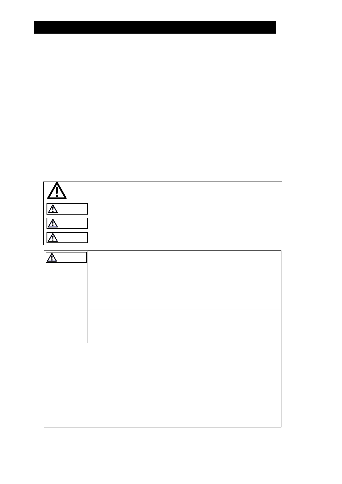
Symbols
2
Indicates a DANGER, WARNING or CAUTION item.
DANGE
WARNING
CAUTION
CAUTION
Indicates an urgent situation which poses a threat of death or
serious injury
Indicates that there is a potential threat of death or serious injury
Indicates that there is a possibility of injury or equipment / product
damage
Install properly and DO NOT use this product outside the
recommended operating pressure, temperature and other
specification ranges.
Improper use may result in such hazards as damage to the product
or malfunctions that may lead to serious accidents. Local
regulations may restrict the use of this product to below the
conditions quoted.
Use hoisting equipment for heavy objects (weighing
approximately 20 kg (44 lb) or more).
Failure to do so may result in back strain or other injury if the object
should fall.
Take measures to prevent people from coming into direct
contact with product outlets.
Failure to do so may result in burns or other injury from the
discharge of fluids.
When disassembling or removing the product, wait until the
internal pressure equals atmospheric pressure and the surface
of the product has cooled to room temperature.
Disassembling or removing the product when it is hot or under
pressure may lead to discharge of fluids, causing burns, other
injuries or damage.
Safety considerations are continued on the next page.
172-65185A-08 (MC-COSR Multi-control Valve) 20 Nov 2014

CAUTION
Be sure to use only the recommended components when
repairing the product, and NEVER attempt to modify the
product in any way.
Failure to observe these precautions may result in damage to the
product and burns or other injury due to malfunction or the
discharge of fluids.
3
Do not use excessive force when connecting threaded pipes to
the product.
Over-tightening may cause breakage leading to fluid discharge,
which may cause burns or other injury.
Use only under conditions in which no freeze-up will occur.
Freezing may damage the product, leading to fluid discharge, which
may cause burns or other injury.
Use only under conditions in which no water hammer will
occur.
The impact of water hammer may damage the product, leading to
fluid discharge, which may cause burns or other injury.
172-65185A-08 (MC-COSR Multi-control Valve) 20 Nov 2014
Specifications
CAUTION
CAUTION
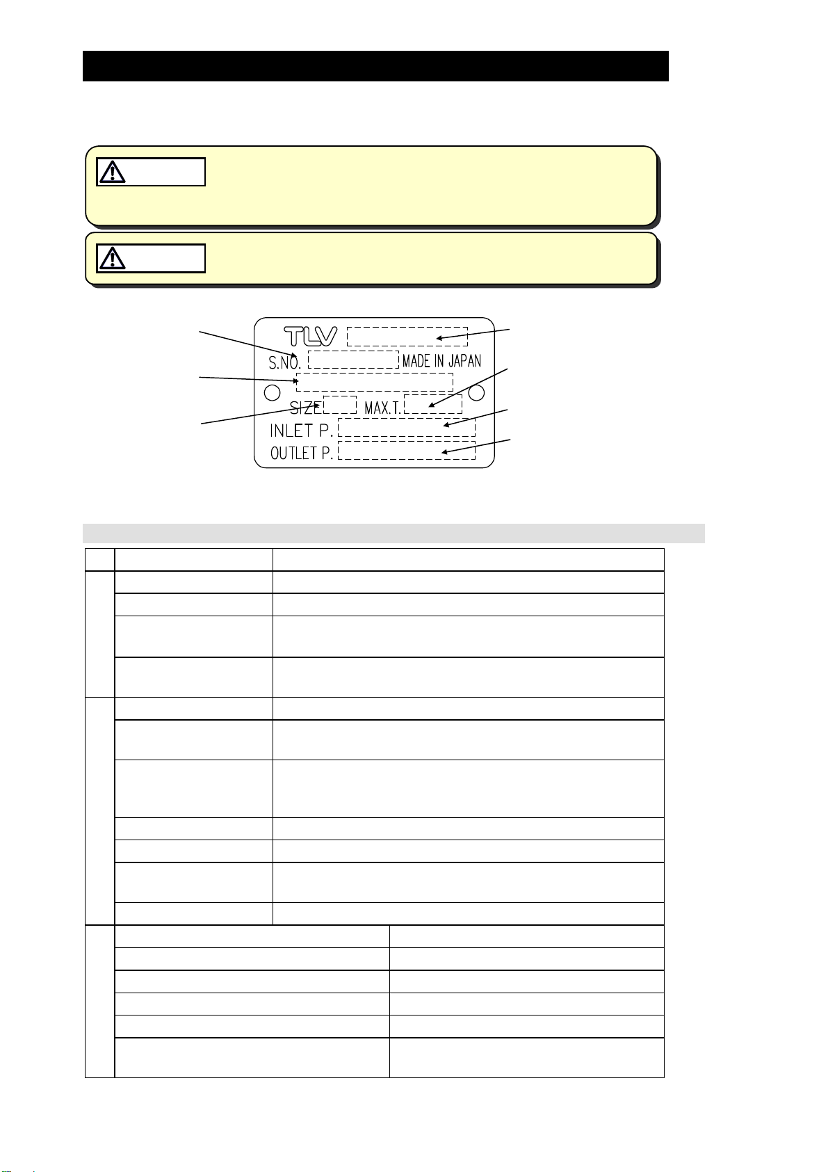
Refer to the product nameplate for detailed specifications.
Install properly and DO NOT use this product outside the recommended
operating pressure, temperature and other specification ranges.
Improper use may result in such hazards as damage to the product or
malfunctions which may lead to serious accidents. Local regulations
may restrict the use of this product to below the conditions quoted.
Use only under conditions in which no freeze-up will occur. Freezing
may damage the product, leading to fluid discharge, which may cause
burns or other injury.
4
Serial Number
Valve No.*
Nominal Diameter
* Valve No. is displayed for products with options. This item is omitted from the nameplate when there are no
options.
Actuator Specifications
Actuator Model MC-GA2
Model
Maximum Operating
Temperature
Primary Pressure Range
Secondary Pressure
Adjustable Range
Power Source Voltage Free between 100 and 240 V AC (50/60 Hz)
Power Consumption With motor running: 75 VA max.
Insulation Resistance
500 V DC, 100 M min. between the power source
terminal and ground terminal
Withstand Voltage Between the power source terminal and ground terminal:
Power Source
1500 V AC, 1 min. or 1800 V AC, 1 second
Drive System Positional control by DC brushless motor
Operation Input
4 – 20 mA DC (input impedance 250 )
(Valve Opening)
Emergency Action Valve fully closed by an operation signal interruption.
When input power is cutoff: held at position just before
power cutoff
Time Rating Continuous
Operation
Thermal Protection Built-in overcurrent protection circuit
Time Required to Fully
Fully closed → fully open: Approx. 15 seconds
Open/Close
Manual Operation Possible with the power OFF
Allowable Ambient Temperature Range 0 to 50 °C (32 to 122 °F)
Allowable Ambient Humidity 10% to 90% RH (without dew)
Allowable altitude 2000m (6600 ft) max.
Vibration Resistance 0.5 G max.
Water Resistance Rain resistant (equivalent to IP54)
Environment
Material Motor cover: Aluminum
Main mounting plate: FC25 (cast iron)
172-65185A-08 (MC-COSR Multi-control Valve) 20 Nov 2014

CV Value
Size
(mm)
(in) (1/2) (3/4) (1) (11/4)(11/2)(2) (21/2) (3) (4) (5) (6)
Cv (US)
Cv (UK)
Kvs (DIN)
15 20 25 32 40 50 65 80 100 125 150
3.8 6.9 11.1 15.5 24.0 37.2 59.3 85.0 128
3.2 5.7 9.2 12.9 20.0 31.0 49.4 70.8 107
3.3 5.9 9.5 13.3 20.6 31.9 50.8 72.9 110
Acceptable Operating Range
Model MC-COSR-3 MC-COSR-16
5
180 275
150 229
154 236
Primary Pressure
Range
Secondary Pressure
Adjustable Range
(All conditions must
be met)
Minimum Adjustable
Flow Rate
0.1 – 0.3 MPaG
(15 – 45 psig)
0.01 – 0.05 MPaG
(1.5 – 7 psig)
5% or greater of
rated flow rate
0.2 – 1.6 MPaG
(30 – 250 psig)
Within 10 – 84% of the primary pressure
(Minimum adjustable pressure of
0.03 MPaG (5 psig))
Allowable pressure differential between
0.07 – 0.85 MPa (10 – 120 psi)
5% or greater of rated flow rate
NOTE:10% or greater of rated flow rate
for sizes 65 – 150 mm (2
1
/2 – 6 in)
(1 MPa = 10.197 kg/cm2)
172-65185A-08 (MC-COSR Multi-control Valve) 20 Nov 2014
Correct Usage of the MC-COSR Multi-control Valve
C
C
CAUTION
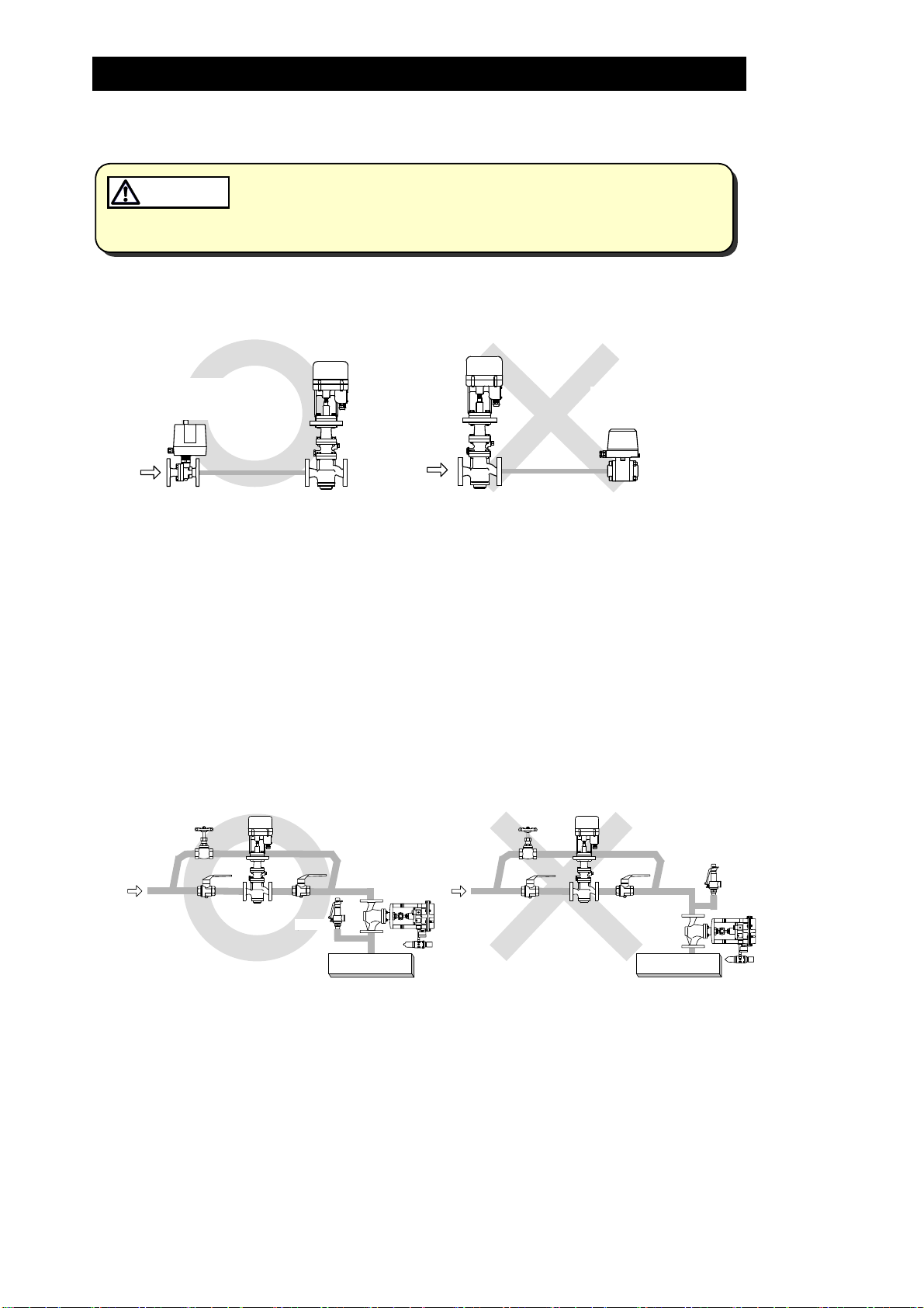
1. The MC-COSR should be operated only within its specifications.
Installing an ON / OFF Valve (Solenoid Valve or Motorized Valve)
2.
Install properly and DO NOT use this product outside the recommended
operating pressure, temperature and other specification ranges.
Improper use may result in such hazards as damage to the product or
malfunctions which may lead to serious accidents. Local regulations
may restrict the use of this product to below the conditions quoted.
MC-COSR
MC-COSR
6
Motorized
Valve
電動弁
Inlet Side
入口側
Outlet Side
出口側
Solenoid
電磁弁
Valve
If an on-off valve, such as a motorized valve, is required to stop supply of steam to the
steam-using equipment, install it at the inlet side of the MC-COSR. If a solenoid valve is
installed at the outlet of the reducing valve, its opening and closing will cause heavy
chattering and may lead to damage of the piston and main valve. (When the on-off
valve opens, the secondary pressure of the multi-control valve changes from zero to the
set pressure, passing through an area of the reducing ratio of less than 10:1, where
adjustment is impossible, chattering occurs momentarily.)
To save energy, install the on-off valve as near to the boiler as possible.
Note: To prevent water hammer, it is recommended that a slow-acting motorized on-off
valve be used. In particular, if a fast-acting on-off solenoid valve is used for
frequent temperature control, the potential water hammer effect can damage the
steam equipment and the multi-control valve.
3. Installing a Control Valve
Safety
安全弁
V ve al
ontrol
制御弁
MC-COSR
Safety
安全弁
Valve
Valve
MC-COSR
ontrol
制御弁
Valve
蒸気使用装置
Equipment
蒸気使用装置
Equipment
A control valve (i.e. for temperature control) installed between the MC-COSR and the
steam equipment (downstream of the MC-COSR) may raise the pressure between the MCCOSR and the control valve when the control valve is closed, depending on their spatial
relationship. Therefore, the control valve should be installed close to the steam equipment.
Also, a safety valve should be installed downstream of the control valve.
Note: When installing a safety valve to protect the steam equipment, be sure to install it
on the steam equipment or directly before the inlet of the steam equipment. If the
safety valve is installed between the MC-COSR and a control valve, an eventual
pressure rise could activate the safety valve.
172-65185A-08 (MC-COSR Multi-control Valve) 20 Nov 2014
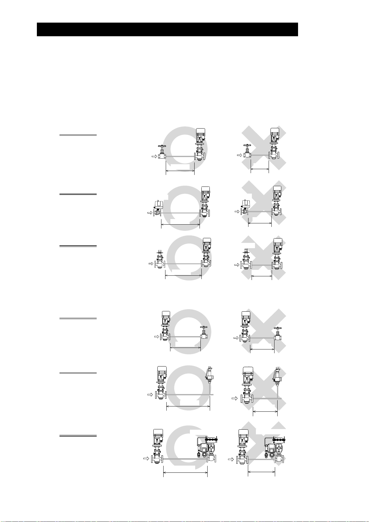
4. Recommended Straight Pipe Runs
L
m
y
In order to ensure stable steam flow, the piping upstream and downstream of the multicontrol valve must be straight runs. If a multi-control valve is installed either directly
before or after an elbow or control valve, unevenness in steam flow may result in
chattering and unstable pressure.
To ensure stable steam flow, it is recommended that the multi-control valve be installed
on straight runs of piping, as illustrated below.
7
Inlet (primary side) of the multi-control valve
Maintain a straight piping run
of 10 d or more
manual valve, a strainer or an
when a
Valve, strainer,
elbow, etc.
elbow, etc. is installed.
(Example: if nominal size is
25 mm (1 in), have 250 mm (10
in) or more)
Maintain a straight piping run
of 30 d or more
automated valve (on-off valve)
when an
Automatic
Valve
自動弁
is installed.
(Example: if nominal size is 25 m
(1 in), have 750 mm (30 in) or
more)
Maintain a straight piping run
of 30 d or more
when another
pressure reducing valve is
installed.
reduction)
(Example: if nominal size is
25 mm (1 in), have 750 mm (30
in) or more)
(Two-stage pressure
Pressure
減圧弁
Reducing Valve
Note: d = pipe diameter
10d以上
10 d or more
30d以上
30 d more or
30d以上
30 d or more
MC-COSR
MC-COSR
MC-COSR
e, strainer,
Valv
elbow, etc.
ess than
10d未満
Automatic
自動弁
Valve
Less than
30d未満
Pressure
Reducing Valve
減圧弁
Less than
10 d
30 d
30d未満
30 d
MC-COSR
MC-COSR
MC-COSR
Outlet (secondary side) of the multi-control valve
Maintain a straight piping run
of 15 d or more
when a
MC-COSR
manual valve, a strainer or an
elbow, etc. is installed.
(Example: if nominal size is
25 mm (1 in), have 375 mm (15
in) or more)
Maintain a straight piping run
of 30 d or more
when a
safety valve is installed.
(Example: if nominal size is
25 mm (1 in), have 750 mm (30
in) or more)
MC-COSR
15d以上
15 d or
30d以上
30
Maintain a straight piping run
of 30 d or more
when a
control valve or an automated
valve (on-off valve) is
installed.
(Example: if nominal size is
25 mm (1 in), have 750 mm (30
in) or more)
MC-COSR
30d以上
30 d or more
172-65185A-08 (MC-COSR Multi-control Valve) 20 Nov 2014
more
Safet
安全弁
Valve
ore d or m
Control or
制御弁または自動弁
Automated Valv
MC-COSR
Less than
15d未満
15 d
Safety
Less than
30d未満
安全弁MC-COSR
Valve
MC-COSR
e
Control or
制御弁または自動弁
Automated Valv
Less than
30d未満
30 d
e
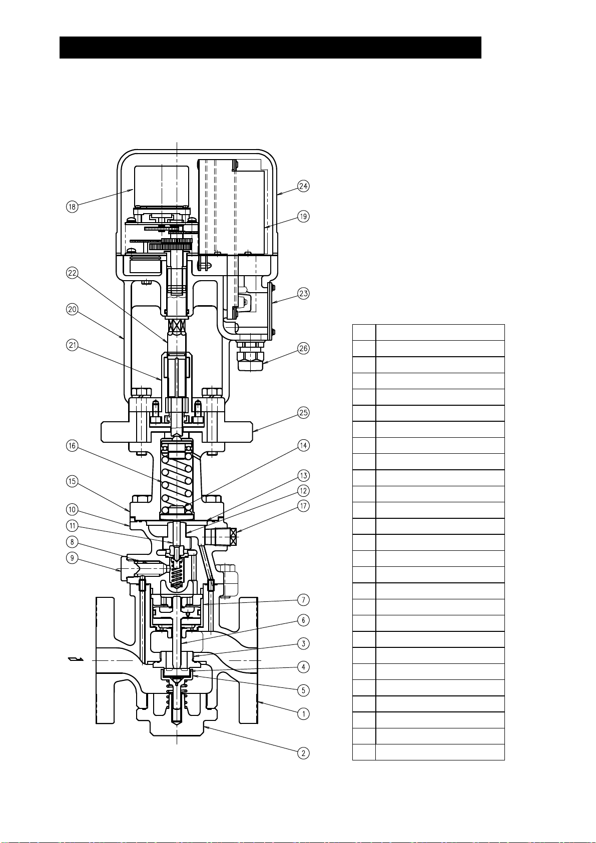
Configuration
15 – 25 mm (1/2 – 1 in)
8
No. Name
1 Main Body
2 (Main Body) Plug
3 Main Valve Seat
4 Main Valve
5 Main Valve Holder
6 Piston
7 Cylinder
8 Pilot Screen
9 Pilot Screen Holder
10 Pilot Body
11 Pilot Valve Stem
12 Pilot Valve Seat
13 Diaphragm
14 Diaphragm Support
15 Spring Housing
16 Coil Spring
17 Plug – Sensing Line Port
18 Motor Unit
19 Drive Unit
20 Mounting Plate
21 Adjustment Screw Guide
22 Adjustment Screw
23 Terminal Block Cover
24 Motor Cover
25 Insulation Plate
172-65185A-08 (MC-COSR Multi-control Valve) 20 Nov 2014
26 Cable Lock

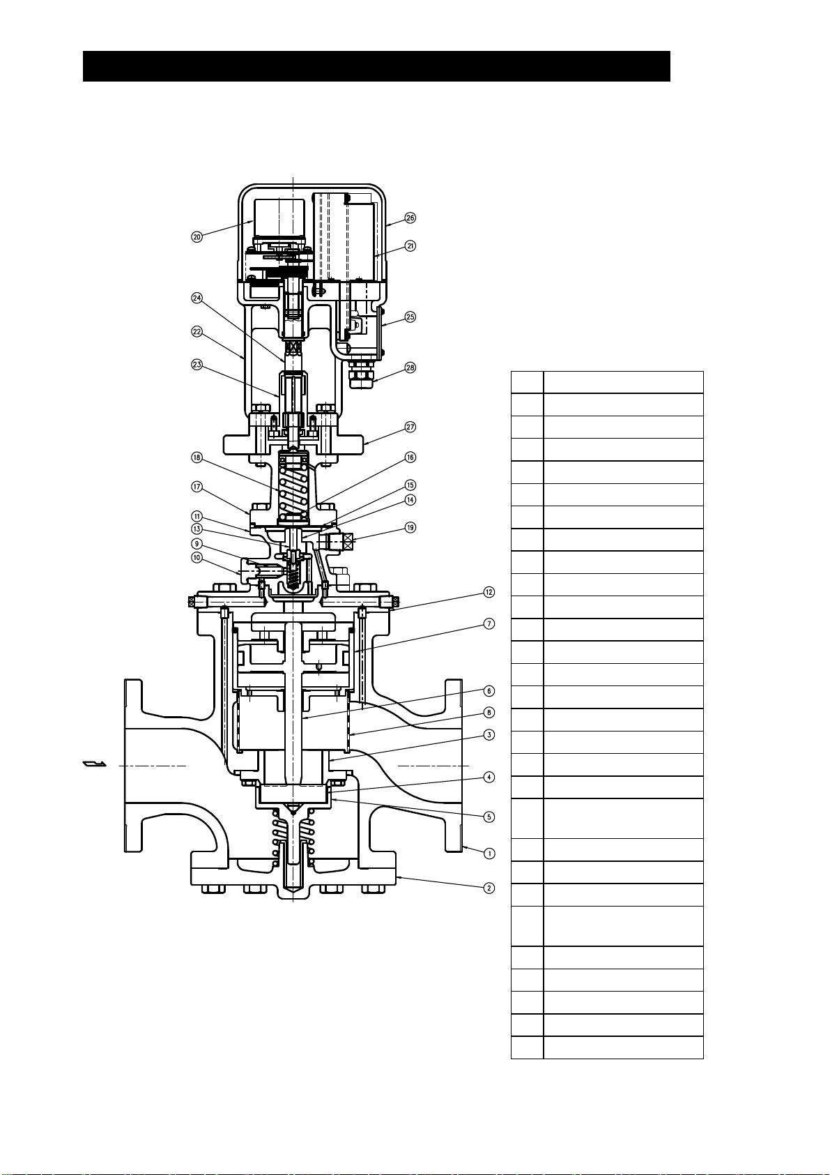
32 – 50 mm (11/4 – 2 in)
No. Name
1 Main Body
2 (Main Body) Cover
3 Main Valve Seat
4 Main Valve
5 Main Valve Holder
6 Piston
7 Cylinder
8 Pilot Screen
9 Pilot Screen Holder
10 Pilot Body
11 Pilot Valve Stem
12 Pilot Valve Seat
13 Diaphragm
14 Diaphragm Support
15 Spring Housing
16 Coil Spring
17 Plug – Sensing Line Port
18 Motor Unit
19 Drive Unit
20 Mounting Plate
21 Adjustment Screw Guide
22 Adjustment Screw
23 Terminal Block Cover
24 Motor Cover
25 Insulation Plate
26 Cable Lock
9
172-65185A-08 (MC-COSR Multi-control Valve) 20 Nov 2014
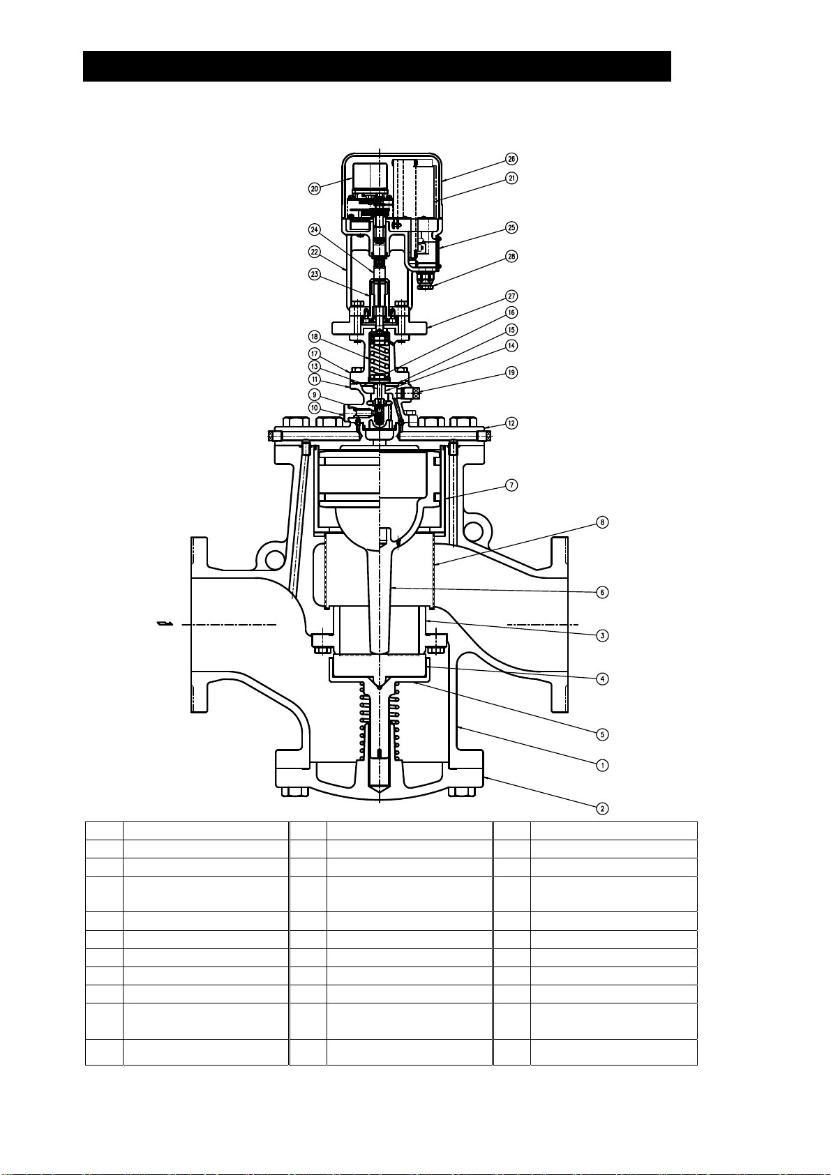
65 – 125 mm (21/2 – 5 in)
No. Name
1 Main Body
2 (Main Body) Cover
3 Main Valve Seat
4 Main Valve
5 Main Valve Holder
6 Piston
7 Cylinder
8 Silencer
9 Pilot Screen
10 Pilot Screen Holder
11 Pilot Body
12 Pilot Cover
13 Pilot Valve Stem
14 Pilot Valve Seat
15 Diaphragm
16 Diaphragm Support
17 Spring Housing
18 Coil Spring
Plug – Sensing Line
19
Port
20 Motor Unit
21 Drive Unit
22 Mounting Plate
Adjustment Screw
23
Guide
24 Adjustment Screw
25 Terminal Block Cover
26 Motor Cover
27 Insulation Plate
28 Cable Lock
10
172-65185A-08 (MC-COSR Multi-control Valve) 20 Nov 2014
150 mm (6 in)
11
No. Name No. Name No. Name
1 Main Body 11 Pilot Body 21 Drive Unit
2 (Main Body) Cover 12 Pilot Cover 22 Mounting Plate
3 Main Valve Seat 13 Pilot Valve Stem 23
4 Main Valve 14 Pilot Valve Seat 24 Adjustment Screw
5 Main Valve Holder 15 Diaphragm 25 Terminal Block Cover
6 Piston 16 Diaphragm Support 26 Motor Cover
7 Cylinder 17 Spring Housing 27 Insulation Plate
8 Silencer 18 Coil Spring 28 Cable Lock
9 Pilot Screen 19
10 Pilot Screen Holder 20 Motor Unit
Plug – Sensing Line
Port
172-65185A-08 (MC-COSR Multi-control Valve) 20 Nov 2014
Adjustment Screw
Guide
 Loading...