

172-65599M-04 (C1CM(-EX)/C1CF(-EX), C1SM(-EX)/C1SF(-EX)) 7 April 2021
Cycle Counter
C1CM / C1CF
C1SM / C1SF
(Standard Model)
C1CM-EX / C1CF-EX
C1SM-EX / C1SF-EX
(ATEX & IECEx Intrinsically Safe Model)
NOTE: This instruction manual has been edited for use with both standard
and intrinsically safe models.
Copyright © 2021 by TLV CO., LTD.
All rights reserved

1
Contents
Introduction ....................................................................... 1
Safety Considerations ....................................................... 2
Operation .......................................................................... 4
Specifications .................................................................... 5
Configuration ..................................................................... 7
Installation ......................................................................... 8
Troubleshooting .............................................................. 12
Product Warranty ............................................................ 14
Introduction
Thank you for purchasing the TLV cycle counter.
This product has been thoroughly inspected before being shipped from the
factory. When the product is delivered, before doing anything else, check the
specifications and external appearance to make sure nothing is out of the
ordinary. Also be sure to read this manual carefully before use and follow the
instructions to be sure of using the product properly.
For products with special order specifications or options, if detailed instructions
for the special order specifications or options are not contained in this manual,
please contact TLV for full details.
This instruction manual is intended for use with the model(s) listed on the front
cover. It is necessary not only for installation but for subsequent maintenance,
disassembly/reassembly and troubleshooting. Please keep it in a safe place
for future reference.
172-65599M-04 (C1CM(-EX)/C1CF(-EX), C1SM(-EX)/C1SF(-EX)) 7 Apr 2021
2
Indicates a DANGER, WARNING or CAUTION item.
DANGER
Indicates an urgent situation which poses a threat of death or
serious injury
WARNING
Indicates that there is a potential threat of death or serious injury
CAUTION
Indicates that there is a possibility of injury or equipment/product
damage
WARNING
C1CM, C1SM, C1CF, and C1SF are not explosion-proof.
Use only the intrinsically safe C1CM-EX, C1SM-EX, C1CF-EX, and
C1SF-EX in hazardous areas. Product markings are provided on
the nameplate attached on the product.
The C1CM-EX, C1SM-EX, C1CF-EX, and C1SF-EX are compliant
with:
ATEX:EN 60079-0:2012, EN 60079-11:2012
IECEx:IEC 60079-0:2011, IEC 60079-11:2011
The C1CM-EX, C1SM-EX, C1CF-EX, and C1SF-EX meet the
following standards for intrinsic safety:
C1CM-EX, C1CF-EX
ATEX:
nnnn II 2G Ex ib IIB T3/T2 Gb
CML 18ATEX2179X
IECEx: Ex ib IIB T3/T2 Gb
IECEx CML 18.0094X
C1SM-EX, C1SF-EX
ATEX:
nnnn II 2G Ex ib IIC T3/T2 Gb
DEKRA 13 ATEX 0039
IECEx: Ex ib IIC T3/T2 Gb
IECEx DEK 13.0004
For hazardous areas, the product should be selected and installed
by trained personnel with knowledge of the hazardous
locations/classifications.
When using the product in hazardous area, please connect it to the
earth in order to avoid the ignition from electrostatic charge.
Safety Considerations
Read this section carefully before use and be sure to follow the instructions.
Installation, inspection, maintenance, repairs, disassembly, adjustment
and valve opening/closing should be carried out only by trained
maintenance personnel.
The precautions listed in this manual are designed to ensure safety and
prevent equipment damage and personal injury. For situations that may
occur as a result of erroneous handling, three different types of cautionary
items are used to indicate the degree of urgency and the scale of potential
damage and danger: DANGER, WARNING and CAUTION.
The three types of cautionary items above are very important for safety: be
sure to observe all of them as they relate to installation, use, maintenance,
and repair. Furthermore, TLV accepts no responsibility for any accidents or
damage occurring as a result of failure to observe these precautions.
Symbols
Continued on the next page
172-65599M-04 (C1CM(-EX)/C1CF(-EX), C1SM(-EX)/C1SF(-EX)) 7 Apr 2021
3
CAUTION
Install properly and DO NOT use this product outside the
recommended operating pressure, temperature and other
specification ranges.
Improper use may result in such hazards as damage to the product
or malfunctions that may lead to serious accidents. Local regulations
may restrict the use of this product to below the conditions quoted.
Make sure that the sensor body is properly tightened.
Insufficient tightening may allow steam to blow out, resulting in burns.
When disassembling or removing the product, wait until the
internal pressure of the PowerTrap equals atmospheric
pressure and the surface of the PowerTrap has cooled to
room temperature.
Disassembling or removing the product when it is hot or under
pressure may lead to discharge of fluids, causing burns, other
injuries or damage.
NEVER attempt to modify the product in any way.
Failure to observe these precautions may result in damage to the
product and burns or other injury due to malfunction or the
discharge or fluids.
Use only under conditions in which no water hammer will occur.
The impact of water hammer may damage the product, leading to
fluid discharge, which may cause burns or other injury.
When installing the product, use the appropriate tool such as
an adjustable wrench.
Using the improper tool may lead to injury or damage to the product.
DO NOT disassemble/modify the product.
This could damage the product and/or the built-in battery, or
cause leakage of battery fluid, leading to burns or other injury.
Battery cells are not user replaceable.
172-65599M-04 (C1CM(-EX)/C1CF(-EX), C1SM(-EX)/C1SF(-EX)) 7 Apr 2021
4
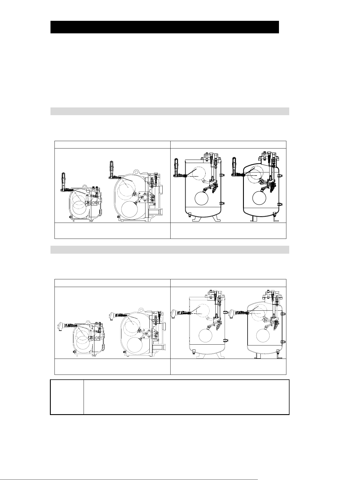
Installation location
C1CM/C1CM-EX
C1CF/C1CF-EX
GP10, GP10L, GP10M
GP14, GP14L, GP14M
GP10F*
GP21F*
Installation location
C1SM/C1SM-EX
C1SF/C1SF-EX
GP10, GP10L, GP10M
GP14, GP14L, GP14M
GP10F*
GP21F*
NOTE
Cycle counter protrudes from the PowerTrap body when installed on the
PowerTrap. Make sure to maintain sufficient installation space as described in
the instruction manual for the PowerTrap.
Do not put extra force onto the cycle counter when lifting the PowerTrap up (for
disassembly or maintenance, etc.).
Operation
Cycle counter is a counter designed for use with GP series TLV PowerTraps. Cycle
counter registers each cycling of the PowerTrap by using its sensor arm to detect the
vertical movement of the PowerTrap's internal float. When the contact points of the
reed switch inside the counter body (or the switch unit) connect, each cycling of the
PowerTrap is counted.
There are two different types of cycle counter available.
Counter Unit Type (with a built-in LCD display) (C1CM/C1CM-EX, C1CF/C1CF-EX)
This type includes a built-in LCD display to display the number of pump cycles of the
PowerTrap. Install the cycle counter using the installation hole on the PowerTrap.
Terminal Box Type (no display) (C1SM/C1SM-EX, C1SF/C1SF-EX)
There is no display on this type. Use the product with a separately prepared selfpowered counter, etc.
*Only available in some countries.
172-65599M-04 (C1CM(-EX)/C1CF(-EX), C1SM(-EX)/C1SF(-EX)) 7 Apr 2021

5
Install properly and DO NOT use this product outside the recommended
operating pressure, temperature and other specification ranges.
Improper use may result in such hazards as damage to the product or
malfunctions which may lead to serious accidents. Local regulations
may restrict the use of this product to below the conditions quoted.
CAUTION
Model
Counter Unit Type*4
Standard Model
Intrinsically Safe Model
C1CM
C1CF
C1CM-EX
C1CF-EX
Installable PowerTrap
Models
GP10, GP14,
GP10L, GP14L,
GP10M, GP14M,
GP10F
GP21F
GP10, GP14,
GP10L, GP14L,
GP10M, GP14M
GP10F
GP21F
Connection
Screwed R(PT) or NPT
Size
15 mm
Maximum Operating
Pressure (PMO)*1/
Maximum Operating
Temperature (TMO)*1
2.1 MPaG / 220 C
Maximum Allowable
Pressure (PMA)*2/
Maximum Allowable
Temperature (TMA)*2
2.1 MPaG/ 260 C
Applicable Fluids*3
Steam Condensate, Water, Steam, Air, Nitrogen
Protection Class
IP 65
Ambient Pressure /
Temperature
Atmospheric / -10 to 55 C
Process Temperature
―
T3:185 C
T2:220 C
Intrinsically Safe:
Certified to meet all of
these standards
―
ATEX:
nnnn II 2G Ex ib IIB T3/T2 Gb
CML 18ATEX2179X
IECEx:
Ex ib IIB T3/T2 Gb
CML 18.0094X
Display
8-digit display LCD
(can be reset*5)
Power Supply
Special built-in lithium battery (3.6 V)
Battery life: Approx. 10 years
(Battery not replaceable*4)
Weight
Approx. 660 g
Accessories
Counter Resetter
*1
Maximum Operating Pressure (PMO) and Maximum Operating Temperature (TMO) are
operating conditions for the inserted portion only.
*2
Maximum allowable pressure (PMA) and maximum allowable temperature (TMA) are
DESIGN CONDITIONS FOR THE INSERTED PORTION, NOT OPERATING
CONDITIONS.
*3
Do not use with toxic, flammable or otherwise hazardous fluids.
*4
Repair parts are not supplied. Once the battery is depleted the entire unit must be
replaced as the battery for the counter unit cannot be taken out or replaced. In addition,
as a used counter unit still contains its built-in battery, please return the unit to TLV or
follow local regulations for disposal.
*5
Once the counter is reset, the previous value is lost and cannot be recovered.
GP10, GP10L, GP10M, GP14, GP14L and GP14M cannot be equipped with a cycle counter
and a liquid level gauge simultaneously but GP10F and GP21F can. GP10F and GP21F are
only available in some countries.
Specifications
C1C Series
172-65599M-04 (C1CM(-EX)/C1CF(-EX), C1SM(-EX)/C1SF(-EX)) 7 Apr 2021

6
C1S Series
Model
Terminal Box Type*4
Standard Model
Intrinsically Safe Model
C1SM
C1SF
C1SM-EX
C1SF-EX
Installable PowerTrap
Models
GP10, GP14,
GP10L, GP14L,
GP10M, GP14M
GP10F
GP21F
GP10, GP14,
GP10L, GP14L,
GP10M, GP14M
GP10F
GP21F
Connection
Screwed R(PT) or NPT
Size
15 mm
Maximum Operating
Pressure (PMO)*1/
Maximum Operating
Temperature (TMO)*1
2.1 MPaG / 220 C
Maximum Allowable
Pressure (PMA)*2/
Maximum Allowable
Temperature (TMA)*2
2.1 MPaG/ 260 C
Applicable Fluids*3
Steam Condensate, Water, Steam, Air, Nitrogen
Protection Class
IP 65*5
Ambient Pressure /
Temperature
Atmospheric /
-45 to 90 C
Atmospheric /
-20 to 80 C
Process Temperature
―
T3:185 C
T2:220 C
Intrinsically Safe:
Certified to meet all of
these standards
―
ATEX:
nnnn II 2G Ex ib IIC T3/T2 Gb
DEKRA 13 ATEX 0039
IECEx:
Ex ib IIC T3/T2 Gb
IECEx DEK 13.0004
Display
―
Power Supply
Max. input power (Pi): 1 W
Max. incoming voltage (Ui): 28 V
Max. incoming current (Ii): 120 mA
Max. internal capacitance (Ci): 3 nF
Max. internal inductance (Li): 0
Note: (Ui)V x (Ii)A ≤ 1 W (Pi)
Weight
Approx. 700 g
Accessories
―
*1
Maximum Operating Pressure (PMO) and Maximum Operating Temperature (TMO) are
operating conditions for the inserted portion only.
*2
Maximum allowable pressure (PMA) and maximum allowable temperature (TMA) are
DESIGN CONDITIONS FOR THE INSERTED PORTION, NOT OPERATING
CONDITIONS.
*3
Do not use with toxic, flammable or otherwise hazardous fluids.
*4
Repair parts are not supplied.
*5
Waterproofing of the wiring inlet should be carried out by the user using a waterproof
cable gland, etc.
GP10, GP10L, GP10M, GP14, GP14L and GP14M cannot be equipped with a cycle counter
and a liquid level gauge simultaneously but GP10F and GP21F can. GP10F and GP21F are
only available in some countries.
172-65599M-04 (C1CM(-EX)/C1CF(-EX), C1SM(-EX)/C1SF(-EX)) 7 Apr 2021

7
R(PT)* or
NPT1/
2
Inserted portion
C1CF
C1CF-EX
C1CM
C1CM-EX
No.
Name
1
Sensor Body
2
Sensor Arm
3
Counter Body
4
Cap
5
Display (LCD)
6
Hex Socket Head Bolt
7
Nameplate
8
LED
9
Magnet Booster Kit
Cycle Counter cannot be
installed on GP series
PowerTraps insulated with
an insulation thickness
exceeding 40 mm.
R(PT)* or
NPT1/
2
Inserted portion
Electrical conduit connection G1/
2
C1SF
C1SF-EX
C1SM
C1SM-EX
No.
Name
1
Sensor Body
2
Sensor Arm
3
Switch Unit
4
Hex Socket Head Bolt
5
Washer
6
Nameplate
7
Terminal Box
8
Magnet Booster Kit
Cycle Counter cannot be
installed on GP series
PowerTraps insulated with an
insulation thickness exceeding
40 mm.
The year of manufacture is included in S. NO. (Serial
Number) on the nameplate.
Please contact TLV for details.
Configuration
Counter Unit Type: C1CM/ C1CM-EX, C1CF/C1CF-EX)
Terminal Box Type: C1SM/C1SM-EX, C1SF/C1SF-EX)
*R(PT) is equivalent to BSPT
172-65599M-04 (C1CM(-EX)/C1CF(-EX), C1SM(-EX)/C1SF(-EX)) 7 Apr 2021

8
C1CM, C1SM, C1CF, and C1SF are not explosion-proof. Use only the
intrinsically safe C1CM-EX, C1SM-EX, C1CF-EX and C1SF-EX in hazardous
areas. For hazardous areas, the product should be selected and installed by
trained personnel with knowledge of the hazardous locations/classifications.
WARNING
Install properly and DO NOT use this product outside the recommended
operating pressure, temperature and other specification ranges.
Improper use may result in such hazards as damage to the product or
malfunctions which may lead to serious accidents. Local regulations
may restrict the use of this product to below the conditions quoted.
CAUTION
Use only under conditions in which no water hammer will occur. The
impact of water hammer may damage the product, leading to fluid
discharge, which may cause burns or other injury.
CAUTION
NEVER attempt to modify the product in any way.
Failure to observe these precautions may result in damage to the product
and burns or other injury due to malfunction or the discharge or fluids.
CAUTION
Make sure that the sensor body is properly tightened.
Insufficient tightening may allow steam to blow out, resulting in burns.
CAUTION
When disassembling or removing the product, wait until the internal
pressure of the PowerTrap equals atmospheric pressure and the surface
of the PowerTrap has cooled to room temperature. Disassembling or
removing the product when it is hot or under pressure may lead to
discharge of fluids, causing burns, other injuries or damage.
CAUTION
Make sure to install the sensor arm without bending.
Make sure to remove any sealing tape or
debris when removing the plug.
NOTE
- Wrap the threaded portion of the sensor body with sealing tape for screwing
into the PowerTrap.
Ensure not to wrap the tape around any part of the sensor body other than
the threaded portion. The cycle counter may not operate properly if tape is
wrapped around a moving part such as the sensor arm.
- Do not use sealant. If sealant adheres to the moving part of the sensor arm it
may interfere with the arm’s movement.
NOTE
Sometimes the display on the counter unit type does not show “0” when
delivered. The number can be reset after installation. Reset as needed. (Refer
to the “Resetting the counter on the LCD display of the counter unit type”
section described later in this manual.)
Installation
Installation, inspection, maintenance, repairs, disassembly, adjustment and valve
opening/closing should be carried out only by trained maintenance personnel.
An explanation for installing cycle counter onto the GP14M PowerTrap is given as
an example. The same procedure should be followed for other models.
1. Remove the plug from the PowerTrap in reference with the installation position in
the “Operation” section. Screw the cycle counter into the place where the plug has
been removed on the PowerTrap by turning it clockwise 4 to 5 times.
172-65599M-04 (C1CM(-EX)/C1CF(-EX), C1SM(-EX)/C1SF(-EX)) 7 Apr 2021

9
For both the counter unit and terminal box types,
use a tool such as an adjustable wrench to grip the
square portion of the sensor body (distance across flats:
30 mm and screw the product in.
Applying a force to any part of the product other than the
square portion may deform or damage the product.
Make sure that the LED on
the tip is facing upwards.
Make sure that the switch
unit is facing upwards.
5
5
°
°
5
5
°
°
Inclination should be within 5.
Connect the wires by
loosening these screws
(size: M4).
(Polarity: left –, right: +)
Do not loosen
these screws.
For the terminal box type, wiring is
necessary to the terminal box.
Before wiring, refer to the
“Specifications” section to make
sure that the supply power voltage
meets these specifications. Make
sure that the wires are securely
connected to the terminal box using
the ring or the spade terminals.
Waterproofing of the wiring inlet
should be carried out using a
waterproof cable gland, etc.
2. The following figure shows the product once installation is complete. Make sure to
screw in the product with the body centered and facing upwards.
3. Before use, the wiring needs to be carried out for the terminal box type. Follow
the figure shown below for the location of the wiring connections.
4. Make sure that the product is properly tightened before proceeding with the test
operation.
For performing a test operation after the product has been installed, follow the
procedure in the PowerTrap instruction manual.
Check motive medium supply piping and other piping connections before
operation. Operation should be carried out by trained personnel.
If the display needs to be reset on the counter unit after the test operation, refer
to the “Resetting the counter on the LCD display of the counter unit” section
described later in this manual.
172-65599M-04 (C1CM(-EX)/C1CF(-EX), C1SM(-EX)/C1SF(-EX)) 7 Apr 2021

10
Cap
Hex Key (2 mm)
Allen Head Bolt
Counter Body
Hex Socket Head Bolt
Lift this part slightly and turn.
NOTE
In order to prevent burns, make sure the product is removed from the
PowerTrap before starting to work.
NOTE
Do not turn the LCD display part more than 360 to the left or right. Turning the
display more than one rotation in either direction could cause disconnection of
internal wiring or other malfunctions.
Adjusting the angle of the LCD display on the counter unit
The angle of the LCD display on the counter unit can be changed.
1. Remove the hex socket head bolt on the counter body.
Turn the cap counterclockwise, then pull up to remove it from the counter body.
2. Once the cap is removed, turn the silicon-molded LCD display so that the LCD
display is readable. After the adjustment is made, put the transparent cap back
on and retighten the hex socket head bolt (tightening torque: 0.5 Nm).
172-65599M-04 (C1CM(-EX)/C1CF(-EX), C1SM(-EX)/C1SF(-EX)) 7 Apr 2021

11
LCD Display
(Counter cannot be reset, by putting
resetter close to the display side.)
Resetter
C1CM/C1CM-EX
C1CF/C1CF-EX
C1SM/C1SM-EX
C1SF/C1SF-EX
Sensor Body
Magnet Booster Kit
Fixed in place
by the counter body
NOTE
Once the counter is reset, the previous value is lost and cannot be recovered.
In addition, failures of the PowerTrap caused by resetting the counter will not
be covered under warranty.
Resetting the counter on the LCD display of the counter unit
The numeric value displayed on the LCD of the counter unit can be reset.
Put the counter resetter close to the back of the LCD display as shown below. (The
cap is removed in the figure below. The counter can be reset without removing the
cap.) After the display clears momentarily, “0” will be displayed. Do not put the
counter resetter close to the cycle counter other than for the purpose of resetting the
counter display. Once the counter is reset to zero, it can not be returned to displaying
the previous numeric value.
Magnet booster kit
If the cycle counter has been used in a high-temperature environment for a long
period of time, the magnetic force of the reed switch becomes weaker, resulting in
operational failure (the counter does not count).
For this reason, the magnet booster kit is installed on the upper part of the sensor
body to prevent operational failure.
This booster kit has a built-in magnet to restore the magnetic force of the reed switch,
preventing operational failure.
Contact TLV in the event if the magnet booster kit falls from the cycle counter.
172-65599M-04 (C1CM(-EX)/C1CF(-EX), C1SM(-EX)/C1SF(-EX)) 7 Apr 2021

12
When disassembling or removing the product, wait until the internal
pressure of the PowerTrap equals atmospheric pressure and the surface
of the PowerTrap has cooled to room temperature. Disassembling or
removing the product when it is hot or under pressure may lead to
discharge of fluids, causing burns, other injuries or damage.
CAUTION
Problem
Cause
Remedy
Counter Unit Typ
e
Nothing is displayed
on the LCD display
Battery has been completely
discharged
Replace with a new counter unit
(The battery itself cannot be
replaced)
Cycle counter is not
operating even though
the PowerTrap is in
operation
(you can hear the
snap action unit
operating sound)
Sensitivity of the sensor is
reduced
Adjust the sensitivity
(See the “Adjusting the sensitivity
for the counter unit type” section)
Dirt or foreign matter has
clogged the hinge part of the
sensor arm, hindering its
movement
Clean the moving area
Terminal Box Type
Cycle counter is not
operating even
though the PowerTrap
is in operation
(you can hear the
snap action unit
operating sound)
Sensitivity of the sensor is
reduced
Adjust the sensitivity
(See the “Adjusting the sensitivity
for the terminal box type” section)
Dirt or foreign matter has
clogged the hinge part of the
sensor arm, hindering its
movement
Clean the moving area
Improper wiring
Readjust the wiring
Troubleshooting
When the product fails to operate properly, use the following table to locate the cause
and remedy.
If problems do not improve even after applying the remedies listed in “Troubleshooting”,
contact TLV.
Sensitivity adjustment for the counter unit type
When operating sounds can be heard from the PowerTrap however the cycle counter
does not count or other symptoms appear, it is possible that the sensitivity of the
sensor (the sensing accuracy of the reed switch) may have lowered due to aging of
the product.
In such cases, the sensitivity of the sensor can be restored by readjusting the
distance between the magnet built in to the sensor body and the built-in reed switch
in the counter body (or the switch unit for the terminal box type)
In this section, this operation is called sensitivity adjustment.
Make sure that the product is removed from the PowerTrap before you make
adjustments. Take precautions against burns, etc. when removing the unit.
1. Loosen the hex socket head bolt holding the counter body in place.
2. Then rotate the counter body as shown in the figure on the next page while
moving the sensor arm up and down. The counter body may be turned in either
direction. Check the sensitivity by turning both ways (to the left and right).
However do not turn more than 15 to the left or right.
3. Once the LED lights up in time with the movement of the sensor arm and has
begun to count properly, the counter is considered to be operating normally.
4. Secure the counter by re-tightening the hex socket head bolt (tightening torque:
1.5 Nm).
172-65599M-04 (C1CM(-EX)/C1CF(-EX), C1SM(-EX)/C1SF(-EX)) 7 Apr 2021

13
Loosen the hex socket head bolt and turn the
counter body slightly to make sure that the
counter is functioning properly.
Adjust the counter body by twisting within 15 to
the left or right. The angle should be adjusted
based on the matching mark on the body.
Loosen the
hex socket head bolt
(Hex key: 3 mm)
Matching Mark
Screw Hole
15
Loosen the hex socket head bolt
(Hex key: 3 mm)
15
Loosen the hex socket head
bolt and turn the switch unit
slightly with a coin, etc. to
make sure that the counter
is functioning properly.
Do not turn the switch unit more than
15 to the left or right. The position of
the hex socket head bolt should be
used to determine the angle.
NOTE
DO NOT turn the body more than 15 to the left or right when adjusting the
sensitivity.
NOTE
When removing/installing the hex socket head bolt, coat threaded portion with
sealing agent to maintain waterproofing.
NOTE
DO NOT turn the body more than 15 to the left or right when adjusting the
sensitivity.
Sensitivity adjustment for the terminal box type
Make sure that the product is removed from the PowerTrap before you make
sensitivity adjustments. Take precautions against burns, etc. when removing the unit.
To adjust the sensitivity, you can use a circuit tester, or else rewiring will be
necessary after removing the unit from the PowerTrap. In this section, we will
describe the adjustment method using a circuit tester.
First, set the range of the circuit tester so that the resistance measurement can be
carried out, then connect the leads to the plus and minus terminals on the terminal
box (refer to the “Installation” section).
Then move the sensor arm up and down and turn the switch unit little by little. The
switch unit may be turned in either direction, however do not turn more than 15 to
the left or right. When the resistance value of the circuit tester changes in time with
the movement of the sensor arm, the unit is considered to be operating normally
After the adjustment is made, retighten the hex socket head bolt (tightening torque:
1.5 Nm).
172-65599M-04 (C1CM(-EX)/C1CF(-EX), C1SM(-EX)/C1SF(-EX)) 7 Apr 2021

14
Product Warranty
1. Warranty Period
One year following product delivery.
2. Warranty Coverage
TLV CO., LTD. warrants this product to the original purchaser to be free from
defective materials and workmanship. Under this warranty, the product will be
repaired or replaced at our option, without charge for parts or labor.
3. This product warranty will not apply to cosmetic defects, nor to any product
whose exterior has been damaged or defaced; nor does it apply in the
following cases:
1) Malfunctions due to improper installation, use, handling, etc., by other
than TLV CO., LTD. authorized service representatives.
2) Malfunctions due to dirt, scale, rust, etc.
3) Malfunctions due to improper disassembly and reassembly, or
inadequate inspection and maintenance by other than TLV CO., LTD.
authorized service representatives.
4) Malfunctions due to disasters or forces of nature.
5) Accidents or malfunctions due to any other cause beyond the control
of TLV CO., LTD.
4. Under no circumstances will TLV CO., LTD. be liable for consequential
economic loss damage or consequential damage to property.
* * * * * * *
For Service or Technical Assistance:
Contact your TLV representative or your regional TLV office.
Manufacturer
881 Nagasuna, Noguchi
Kakogawa, Hyogo 675-8511, JAPAN
Tel: 81-(0)79-427-1800
172-65599M-04 (C1CM(-EX)/C1CF(-EX), C1SM(-EX)/C1SF(-EX)) 7 Apr 2021
 Loading...