

TL Ultralight TL 3000 Sirius Flight And Operation Manual
Aircraft s/n:________________ Registration no._____________:
T L - U L T R A L I G H T
Airport, building 84
503 41 Hradec Kralove
tel/fax: +420 4952 13378
tel +420 4952 11753
tel +420 4952 18910
info@tl-ultralight.cz
www.tl-ultralight.cz
T L - 3 0 0 0 S I R I U S
F l i g h t a n d o p e r a t i o n a l
m a n u a l
P u b l i s h e d i n J a n u a r y 2 0 0 9
r e v
1

Page 2 of 68
This page blank for notes:

Page 3 of 68
1. GENERAL INFORMATION ...............................................................................................8
1.1. Important Information ......................................................................................................................... 8
1.2. Description of the aircraft.................................................................................................................... 8
1.2.1. Airframe ............................................................................................... .............. .................... ............... 8
1.2.2. Fuel system .......................................................................................................................................... 9
1.2.3. Propeller................................................................................................................................................ 9
1.2.4. Engine ............................................................................................... .............. .................... .................. 9
1.2.5. Control movements........................................................................................................................... 10
1.2.6. Basic technical data of the airplane................... ............................................................................. 12
1.3. Layout of the airplane ......................................................................................................................... 13
1.4. Detecting the center of gravity position, allowed and measured values ........................... 14
1.4.1. Weighing the airplane for the foreword center of gravity position ............................................ 15
1.4.2. Weighing the airplane for the backmost center of gravity .................................................. ........ 15
2. OPERATING RESTRICTIONS....................................................................................... 15
2.1. Flight operation speeds and position fault of the Air Speed Indicator ............................... 15
2.1.1. Air-speed data and position fault of Pitot tube ............................................................................. 16
2.1.2. Reparation table of real and indicated air-velocity in km/h........................................................ 17
2.2. Weights and loads ................................................................................................................................ 17
2.2.1. Maximum and minimum weights .................................................................................................... 17
2.2.2. Weight of the empty airplane and detected position of the point of balance........................... 17
Real weight of empty aircraft determinate by scaling…………………………………_______kg .................... 17
2.2.3. Positioning of the load .......................................................................... ............................................ 18
2.3. Engine operating restrictions ........................................................................................................... 18
2.3. Propeller operating restrictions....................................................................................................... 19
2.4. Fuel and lubricant oil ........................................................................................................................... 19
2.4.1. Fuel supply .................................................................... ..................................................................... 19
2.4.2. Consumption of fuel .......................................................................................................................... 20
2.5. Restriction of maneuver ..................................................................................................................... 20
2.5.1. Allowed turns ..................................................................................................................................... 21
2.5.2. Flight multiples .................................................................................................................................. 21
2.6. The crew .................................................................................................................................................. 21
2.6.1. Minimum and maximum weight of the crew ................................................................................. 21
2.6.2. Pilot´s qualification ........................................................................................................................... 22
2.6.3. Pilot’s place on the plane, age of the crew, using the seat belts ............................................... 23

Page 4 of 68
2.7. Maximum flight height ........................................................................................................................ 23
2.8. Meteorological condition restriction............................................................................................... 23
2.9. Carriage of restricted goods.............................................................................................................. 25
2.10. Types of airport traffic...................................................................................................................... 25
3. EMERGENCY PROCEDURES..........................................................................................26
3.1. Misfire of the engine ............................................................................................................................ 26
3.1.1. Failure of the engine during the flight to the height 200m.. ....................................................... 26
3.1.2. Failure of the engine during the flight above the height 200m.................................................. 26
3.2. Fire on board of the plane.................................................................................................................. 27
3.3. Vibrations ................................................................................................................................................ 27
3.4. Undercarriage failure........................................................................................................................... 28
3.4.1. Main undercarriage failure ............................................................................................................... 28
3.4.2. Front undercarriage failure .............................................................................................................. 28
3.5. Using the saving system..................................................................................................................... 28
4. OPERATING PROCEDURES .......................................................................................... 29
4.1. Starting up the engine ........................................................................................................................ 29
4.2. Engine test .............................................................................................................................................. 29
4.3. Important parts made before getting off ..................................................................................... 30
4.4. Taxiing ...................................................................................................................................................... 32
4.5. Taking-off ................................................................................................................................................ 32
4.5.1. Maximum power of wind at time of taking off .............................................................................. 33
4.6. Tasks after reaching the flight level ............................................................................................... 33
4.7. Flight at the flight level....................................................................................................................... 33
4.8. Descent..................................................................................................................................................... 34
4.8.1. Sideslip................................................................................................................................................ 35
4.9. Landing..................................................................................................................................................... 35
4.10. Tasks after landing ............................................................................................................................ 35
4.11. Flying in lateral wind......................................................................................................................... 37
4.12. Flight in turbulent atmosphere ...................................................................................................... 37

Page 5 of 68
4.13. Standing up to the plane.................................................................................................................. 37
5. PERFORMANCE ................................................................................................................ 37
5.1. Assumptions for performance calculations .................................................................................. 37
5.2. Speeds ...................................................................................................................................................... 38
5.3. Rate of climbs and height loss from the beginning of stalling .............................................. 38
5.4. Ceiling ....................................................................................................................................................... 38
5.5. Gliding range .......................................................................................................................................... 38
5.7. Landing length ....................................................................................................................................... 40
5.8. Maximum Endurance ........................................................................................................................... 41
5.9. Flying range ............................................................................................................................................ 42
6. MAINTENANCE AND OPERATING THE PLANE ...................................................... 42
6.2. Anchorage of the airplane.................................................................................................................. 42
6.4. Assembly and disassembly of the plane........................................................................................ 44
6.4.1. Disassembly of the plane ................................................................................................................. 44
6.4.2. Assembly of the plane ...................................................................................................................... 46
6.5. Washing and cleaning the plane ...................................................................................................... 46
6.7 Filling the fuel ......................................................................................................................................... 51
7. SERVICE LIFE OF AIRPLANE AND PERIODIC MAINTENANCE........................ 52
7.1. Service life of the plane and its parts ............................................................................................ 52
7.2. Daily maintenance ................................................................................................................................ 53
7.2.1. Lubricant plan and lubricant types ................................................................... .............................. 53
7.2.2. Ground Handling...... .................... ...................................................................................................... 54
7.2.3. Removal of the front wheel.............................................................................................................. 54
7.2.4. Wheel disassembly of main undercarriage ............... ..................................................................... 56
7.2.5. Mending the tire ................................................................................................................................ 56
7.2.6. Electrical system voltage.................................................................................................................. 57
7.2.7. Tolerance and setting up values ............... .................... .................................................................. 58
7.2.8. Supporting and subordinate construction...................................................................................... 58
7.2.9. Assembly of the aircraft ................................................................................................................... 58
7.2.10. Special tools..................................................................................................................................... 58
7.2.11. Materials for minor repair to the aircraft surface repairs .......................................................... 58
7.2.12 Changing the fuel filter in the engine area................................................................................... 59
7.2.13 Maintenance of SR 2000/3000 Woodcomp Propeller .................................................................. 60

Page 6 of 68
7.3. Warranty Service .................................................................................................................................. 60
7.4. Periodical revision after every 50hours ........................................................................................ 60
7.5. Periodical revision after every 100hours ...................................................................................... 60
7.6. Periodical revision after every 200hours ...................................................................................... 61
7.7. Inspection after every 300hours ..................................................................................................... 61
7.8. Jacking points on the plane............................................................................................................... 61
7.9. List of labels and their placing ......................................................................................................... 62
8. AIRPLANE REPAIRS.......................................................................................................62
8.1. Repairs of nuts and bolts ................................................................................................................... 62
8.2. Repairs of rivet joints.......................................................................................................................... 62
8.3. Control system repairs ........................................................................................................................ 62
8.4. Airframe repair ...................................................................................................................................... 63
8.5. Fuel system repairs.............................................................................................................................. 63
8.6. Engine repairs ........................................................................................................................................ 63
8.7. Electronic and appliance repairs...................................................................................................... 63
8.8. Inspection of electrical system ........................................................................................................ 64
9. ENGINE ROTAX 912, 912S AND 914 MAINTENANCE ........................................ 65
9.1. Oil refill..................................................................................................................................................... 65
9.2. Spark plugs ............................................................................................................................................. 65
9.3. Refrigerating liquid .............................................................................................................................. 66
9.4. Service life, revision and engine revisions ................................................................................... 67
9.5. Service life of rubber parts of engine............................................................................................. 68

Page 7 of 68
Dear Aircraft Purchaser,
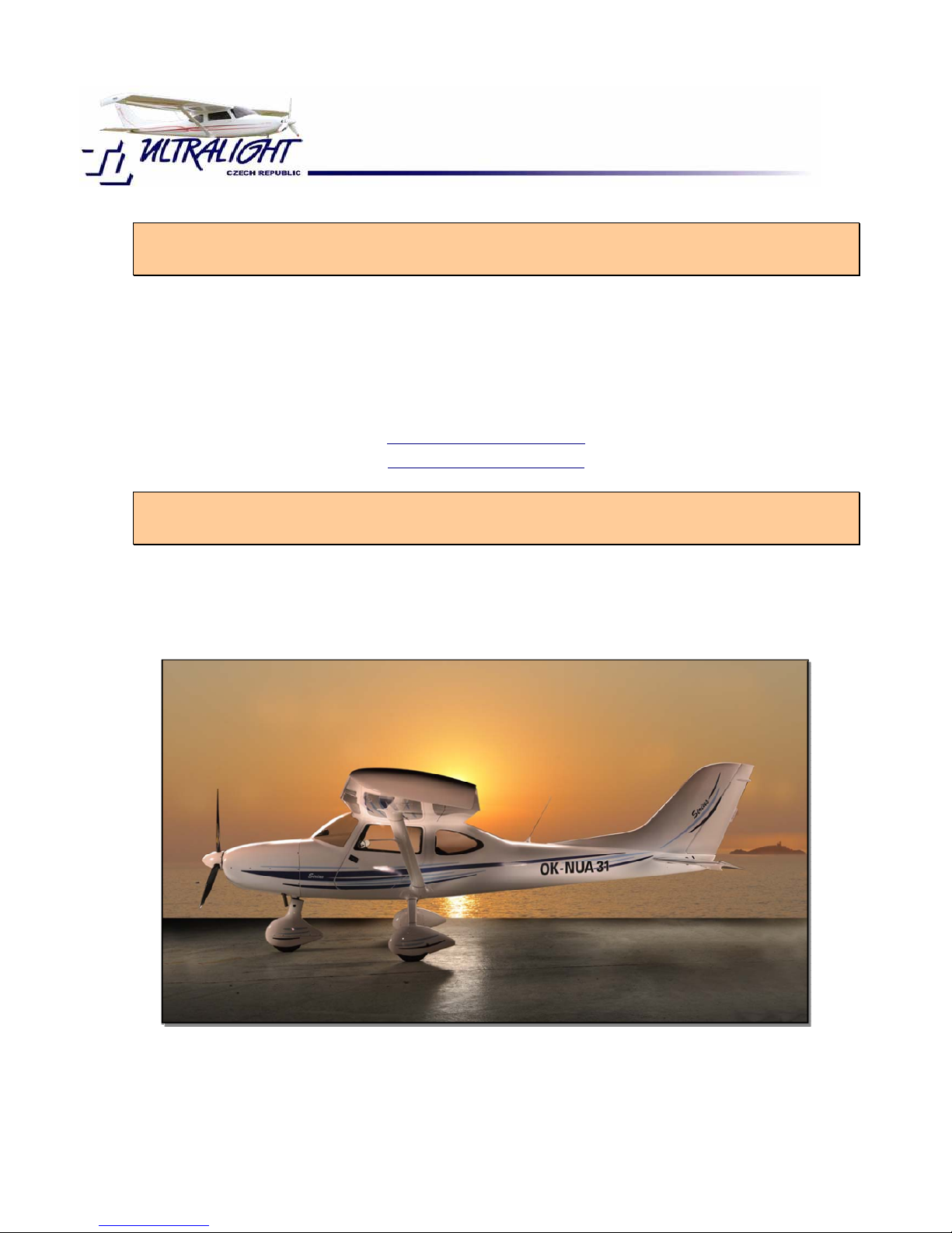
I would like to compliment you on the purchase of the ultra light airplane TL-3000
Sirius which is the result of many years of development by our company. The company
TL-Ultralight strives to be a leading supplier of quality aircraft both in the Czech
Republic and worldwide.
The TL-3000 Sirius provides outstanding performance in the small sports airplanes
category, flying in the TL-3000 Sirius is very economical and its maintenance is also
much easier than conventional aircraft.
I believe that the airplane will be very satisfying and provide you with years of pure
enjoyment. This Flight manual and operating guidebook should help you become
familiar with your new aircraft, please study and become familiar with this manual and
the respective manuals for the propeller and rescue system if fitted.
I wish you a lot of joy from flying with your new airplane the TL-3000 Sirius.
In Hradec Králové 1st January 2009.
TL Ultralight L.T.D.
Jiří Tlustý
TL-ULTRALIGHT s.r.o.
Airport, building 84
503 41 Hradec Kralove
tel/fax 495213378
tel 495218910,5211753
info@tl-ultralight.cz
www.tl-ultralight.cz

Page 8 of 68
1. General Information
In case this guidebook refers to the rule UL1, UL 2 or UL 3, it is only referring to the
corresponding rules of Letecké amatérské asociace české republiky – Czech Republic
amateur flight association. This association is controlled by Úřad pro civilní letectvíOffice for civil aviation Czech Republic.
1.1. Important Information
Every airplane owner, operational organization and pilots who fly this TL-3000 Sirius
must acquaint with this guidebook at its full length. This manual consists of flying and
maintenance for this type of airplane. This manual must be on board of the plane with
other documents for all flights.
It should be kept with the operating instructions for engine, propeller and the rescue
parachute system if fitted.
This airplane is intended to be used for sports and recreational purposes. Also for
performing basic and advanced flight training. It is certificated by technical guideline UL
2 and it is not allowed to make commercial flights with the exception of training and
hire.
This manual is only valid if any changes sent to the aircraft owner are put into this
manual. Superseded pages should be changed in the manual.
ATTENTION!
This airplane belongs to the sports and recreational category and is dateless to the
approbation of UCL v ČR-Office for civil aviation in Czech Republic. Operating this
airplane is at your own risk.
1.2. Description of the aircraft
1.2.1. Airframe
The TL-3000 Sirius is two-placed all composite high wing plane.
The fuselage is laminated, in some places made into sandwich, with oval cross section
shaped to achieve the best proportions whilst maintaining rigidity, low weight and low
aerodynamic drag.
The undercarriage has three wheels with hydraulic disk brakes on the rear wheels. The
main wheel suspension is from laminated composite spring. The front wheel is
steerable. The brakes are foot-operated from the pilot’s side only; each wheel can be
braked separately. The wheels can be equipped with wheel spats.

Page 9 of 68
The cabin is arranged with seats next to each other – side-by-side, remarkable view
into all sides is provided by windows. Locking of two side doors is point-to-point. The
door windows are equipped with rotating vents or sliding windows.
The controls for the airplane are duplicated, arranged with a steering yokes. A control
rod controls the elevator; rudder is controlled by wires, the ailerons are controlled by
control rods. The flaps are controlled by servo engine.
The wing is rectangle shaped in root part, in the outer side is trapezoidal full composite
with main and rear spar made from carbon fiber with sandwich skin. Flaps are
composite, folding down type, operate in three-positions (in the manual mode it is
possible to set any position)
The elevator is also composite; it is supplied with a trim tab, and provides the
longitudinal trim of the airplane. The design of the elevator contributes to the low
aerodynamic drag of the airplane.
1.2.2. Fuel system
The fuel system consists of two fuel tanks placed in wings. It is supplied with fuel level
gauge, on/off cock, filter and mechanical fuel pump for engine types 912UL and
912ULS. The 914 Turbo fuel supply is supplied electrically through a supplemental
electric pump.
Both fuel tanks are equipped with lockable lid placed in the front upper wing skin.
1.2.3. Propeller
It is possible to use a fixed pitch or in-flight adjustable propeller. The manual for your
propeller is provided with the airplane as is the appropriate operations manual.
1.2.4. Engine
Most commonly used engines are Rotax 912UL, 912ULS and 914, which provide the
aircraft with excellent dynamic and flying performance. The Rotax 912UL, 912ULS and
914 are four-stroke four-cylinder engines the type boxer. The cylinder head is liquid
cooled and the cylinders are cooled by air.
There is a gearbox reducer on the engine; the engine has two carburetors. Detailed
information is provided with the aircraft on operation and maintenance of the engine.

Page 10 of 68
ATTENTION!
Some engines are not certificated as flying engines. Even though maximum attention
is paid during the manufacture of the engine, misfire of the engine can occur at any
time. The pilot is responsible for the consequences associated with flying this aircraft.
The obligation of the pilot to fly at all times where in the event of an engine failure they
are able to glide and land safely to a pre-selected area.
1.2.5. Control movements
Pilots Feet
Pushing on the left foot pedal, the airplane turns to the left if on land or in the air,
pushing on the right pedal it turns to right on land or in the air.
Steering
Pulling the steering yokes to the pilot’s body will cause the airplane to rise; pushing
away the steering yokes will cause the airplane to descend.
Braking
The wheels of the main undercarriage have Hydraulic disk brakes, the control is only
from the left seat, pushing on the top part of the left pedal will break the left wheel and
pushing on the top right pedal will break the right wheel. Applying pressure to the top
of both pedals simultaneously will break both wheels.
Flaps
The flaps are electronically controlled by flap instrument placed in the panel board. In
the mode AUTO the flaps are automatically pulled out by controller into the basic
positions 10.5, 28 and 45 degrees. In the mode MAN any flap deflection can be set up
by the controller. Final deflection positions are secured by backstops.
Trim
The trim lever is located in the center panel alongside the throttle, the trim level has
three positions; center for takeoff, forwards for traveling at speed and back for landing
when the flaps are deployed.
Throttle lever

Page 11 of 68
The Throttle Lever is located between the pilot and passenger in the center console,
forward represents full throttle and backwards returns the engine to idle.
Page 12 of 68
1.2.6. Basic technical data of the airplane
Wing span
Length
Height
Wing area
Root profile depth
Ending profile depth
Wing aspect ratio
Surface loading
Aileron span
Aileron area
Aileron deflections up
down
Lifting flaps (ea)
Span
Flap area
Flap deflections start
intermediate position
landing
Horizontal tail fin
Span
Area
Elevator deflection up
down
Vertical tail fin
Area
Rudder deflection +/-
Main wheel-spacing
Wheel base
Wheel dimensions
Atmospheric pressure in tires
Brakes
Rebound of main undercarriage
Rebound of the front wheel
Volume of the fuel tank
Weight of empty airplane
C.G. positon of empty airplane
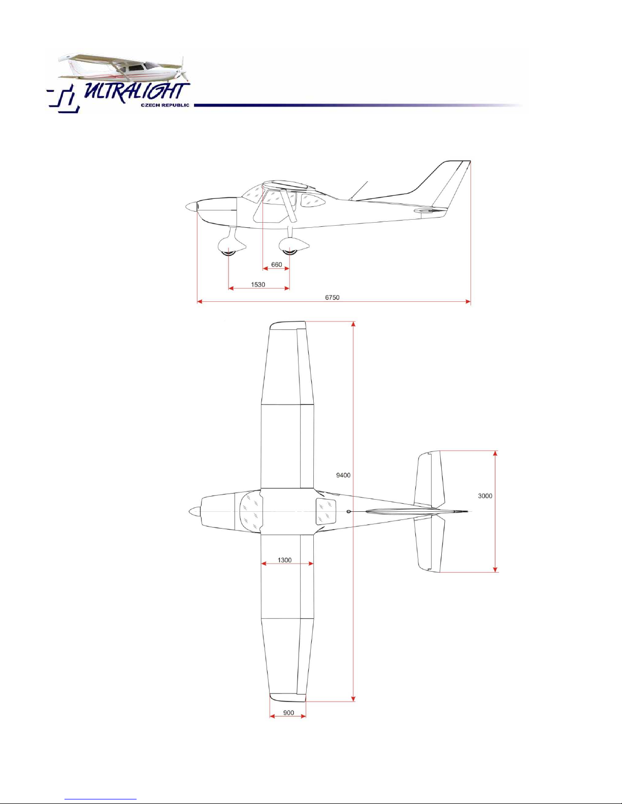
9.40m
6.75m
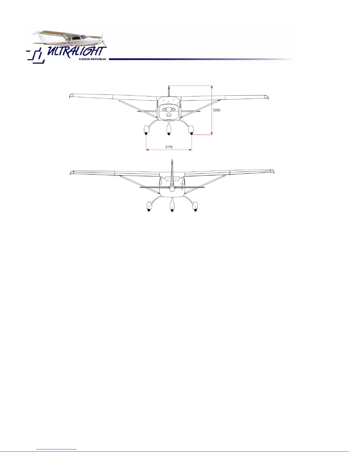
2.25m
11.15m2
1.30m
.90m
7.92
40.30kg/m2
1.87m
0.51m2
11.50o
7.60o
2.07m
0.66m2
10.50o
28.00o
45.00o
3.00m
2.01m2
16.70o
8.50o
1.19m2
20.00
o
30.00o
2.17m
1.53m
300x150
2.0kPa
hydraulic disk brakes
tires, resilience of the legs of the undercarriage
coil spring
130 liters
See 2.2.2.
See 2.2.2.
Page 13 of 68
1.3. Layout of the airplane
Dimensioned Layout of the TL-3000 Sirius
Page 14 of 68
1.4. Detecting the center of gravity position, allowed and measured values
Observance of the center of gravity is vital for the stability and manageability of the
airplane. That’s why it is necessary for every airplane pilot to know how to diagnose the
center gravity position of the airplane for different occupancy.
It is necessary to know the length of the middle aerodynamic range when making the
calculation of the center of gravity. Calculated center of gravity must be inside the
range given by the producer.
Length of middle aerodynamic substance of the wing . SAT =1230mm
Allowed range of the center of gravity in %SAT 21-34 %
From minimal pilot weight 60kg up to maximum take-off weight of the aircraft, with all
combinations of fuel amount (from zero to 130l) and baggage in the rear luggage
compartment behind seats (up to 20kg) the aircraft is found in allowed range of flight
c.g. position.
When detecting the point of balance and subsequent calculation let the airplane stand
in flying position on three weighing machines and proceed following these instructions:

Page 15 of 68
1.4.1. Weighing the airplane for the foreword center of gravity position
• Pilot’s seat is occupied with a pilot with the lowest allowed weight
• There cannot be any load on the plane; the fuel tank must be full
• Measure the weight of the rear wheels; add the left side and the right side
together. The total weight on the rear wheels is known as Gp.
• The weight Go is measured under the front wheel.
• Total weight of the airplane Gvzl. is equal to the sum of Gp+Go
• Measure the distance of axle of the main undercarriage from the axle of the front
wheel Lb in millimeters (Lb=1530mm)
• Measure the distance of leading edge of the wing with a plum bob from the axle
of the main undercarriage La in millimeters (La=660mm)
• Measure the horizontal distance of the point of balance from the axle of main
undercarriage Lt by the formula: Lt=Go*Lb/Gvzl
• Measure the distance of the point of balance from the leading edge of the wing Xt
by the formula: Xt=La-Lt
• Calculate the front center of gravity in percents by the formula: X%=(Xt-
34)/SAT*100 where 34mm is distance of SAT beginning from wing leading edge.
1.4.2. Weighing the airplane for the backmost center of gravity
Pilot’s seat and the seat next to the pilot must be occupied with maximum weight of the
crew, put maximal load into the luggage compartment of useful load and fill the fuel
tank. While loading the aircraft be aware that the total weight does not exceed
maximum take-off weight. The procedure of measuring and weighing is the same as
detecting the front center of gravity
2. Operating restrictions
2.1. Flight operation speeds and position fault of the Air Speed Indicator
Presented speeds of the flight apply to the maximum takeoff weight of 450kg and at
the conditions of the sea level by the MSA. The speeds are presented in kilometers per
hour and Knots.

Page 16 of 68
Take off speed
Climb speed
Cruising speed
Accession landing (approach)
The speed of bearing the surface (landing)
Maximum speed of horizontal flight
Design turnover speed V
A
160 is due to diagram V – n in Type design
Never never-exceed speed Vne
Maximum speed at turbulence
Stalling speed with no flaps
Stalling speed with flaps 60o 3rd grade flap
Max.speed for extending the 1st grade flaps Vfe
Max.speed for extending the 2nd grade flaps Vfe
Max.speed for extending the 3rd grade flaps Vfe
Km/h
75
120
180-230
120
62
230
160
253
200
80
62
140
120
105
Knots
40
65
97-124
65
34
124
86
137
108
43
34
76
65
57
Vne is the never-exceed speed, which the airplane cannot be flown over.
VA Do not use full control deflection above this speed, neither perform fast action into
the control – the aircraft could be overloaded
Vfe is the maximum speed for extending the flaps; there are the same speed
restrictions for the flight with extended flaps as for their extension.
2.1.1. Air-speed data and position fault of Pitot tube
The speed data reported by the air-speed indicator generally do not correspond at all
speed ranges to the real aerial speed.
That’s why we introduce the reparation of the indicated values for several of the speed
ranges. The real speed is at about 2.3% - 4.1% lower than the speed indicated by the
board air-speed recorder. At low speed the relative mistake is lower and at higher
speed the mistake is increasing.

Page 17 of 68
For safety reasons not extending the maximum allowed speeds we choose the type of
lower real calibrated speed than the indicated speed. All speed limits introduced in this
guidebook as operating restrictions are initiated as the speeds indicated by the airspeed recorder. There is no need for any recount in the way of functioning of the
airplane.
2.1.2. Reparation table of real and indicated air-velocity in km/h
Indicated Actual Indicated Actual Indicated Actual
60
70
80
90
100
120
130
140
150
58
63
72
85
94
112
121
130
139
160
170
180
190
200
210
220
230
240
148
157
167
176
185
194
204
214
224
250
260
275
280
285
290
234
244
255
261
268
279
2.2. Weights and loads
2.2.1. Maximum and minimum weights
Maximum takeoff weight
Maximum takeoff weight with parachute
Maximum landing weight
Maximum weight of the fuel
Maximum load of one seat
Maximum weight of load behind the seats
Minimum weight of the crew
450kg
468kg
450kg
90kg
90kg
20kg
60kg
2.2.2. Weight of the empty airplane and detected position of the point of balance
Real weight of empty aircraft determinate by scaling…………………………………_______kg
C.G. position of empty aircraft……………………………………………………………_______%
Page 18 of 68
Fuel amount in
the fuel tank
liters
Max.allowed
crew weight
without baggage
/ kg /
C.G.
/ % /
Max.allowed
Crew weight with
baggage 20 kg
/ kg /
C.G.
/ % /
Full
130
3 / 4
98
1 / 2
65
1 / 4
32
30min of flight
8
2.2.3. Positioning of the load
Maximum weight of load is 20kg which must be fixed or properly tight in luggage
compartment behind seats.
2.3. Engine operating restrictions
ATTENTION!
Engines Rotax are not certificated as flying engines and sudden misfire
can occur at any time, which can lead to emergency landing. Never fly
with this engine at conditions when safe landing without using the
engine is possible. There is no life service or safety certificate initiated
to this engine. Also it does not correspond to any aerial standards.
All risks and the responsibility with using and operating this engine of
this airplane are on the side of the user. We inform you, as the user,
with the possibility of sudden misfire of the engine.
Engine restrictions for engines Rotax 912UL, 912ULS and 914.
Minimum temperature of air when taking off in Celsius
Maximum temperature of air when taking off
Maximum engine r
evolutions 1/min
Maximum steady revolutions 1/min
Maximum time of running the engine at maximum revolutions
No-load speed
-25
+50
5.800
5.500
5 min
1,400
This data can slightly differ from the actual conduct of the engine, for more details look
at the Instruction manual for using the engine

Page 19 of 68
2.3. Propeller operating restrictions
There is a general requirement for protecting the propeller against the effects of rain
and sun when not in actual use. Covers for your propeller blades were delivered
together with your propeller and please, use them at any time when your airplane is
parked for any time.
Any damage which results in increased vibration is necessary to abort the flight and
make repairs according to the manufacturer’s instructions.
There is a technical description and maintenance checklist for the propeller which you
should go through. The supplied propeller was chosen due to match the engine and
aircraft you have chosen.
The propeller is subject to regular maintenance by the producer, it will require ongoing
maintenance throughout the life of the aircraft.
2.4. Fuel and lubricant oil
For engine Rotax 912, 912S and 914 there are many approved fuel types. Details are
enclosed in the instruction for maintenance for the engine. It is our experience that we
recommend using the petrol Premium Unleaded. Peruse the demands for the fuel
prescribed by the producer in detail. In emergency to know what other fuel is possible
to use.
There are also conditions prescribed by the producer for the oil used in the engine and
these conditions are also enclosed in the instruction for maintenance for the engine. It
is our experience that we recommend the oil Castrol R4. There are types of oil with
which can reduce the service intervals and shorten them from 100 to 50 flight hours.
These details are in the instructions of maintenance for the engine.
2.4.1. Fuel supply
Total volume of tanks
Unusable supply
Minimum amount of fuel when taking off
130litres
5litres
10 liters
Unusable supply is the amount of fuel remaining in the tanks which cannot be used in
general flight.

Page 20 of 68
2.4.2. Consumption of fuel
The consumption of fuel expressively depends on the type of propeller, engine, and the
technique of the pilot, total weight of the airplane, height of the flight, flight regime and
the consumption is expressively influenced by the meteorological conditions with the
consumption being increased with higher temperature. In general, flight with heavier
airplane requires higher engine output because for reaching needed rising force it needs
to be progressed with bigger angle of incidence, so the aerodynamic resistance is
higher.
Aerodynamic resistance is also increasing with second power of the speed of the flight
and that’s why the consumption of the fuel is increasing with higher speed. The
consumption-output of engine curve is enclosed in the instruction for maintenance for
the engine. Also used propeller expressively influences the consumption. Positioning the
angle of incidence of the propeller blades can be a compromise among many various
flight regimes at stationary or adjustable propellers. Using adjustable propeller can the
consumption decrease by 10-15%.
The average consumption for steady running flight with the speed of 170kmh using the
engine Rotax 912 or 914 and using the on land adjustable 3blade propeller at the
weight of the airplane 450kg.
With using the fuel computer, which also evaluates the immediate hour consumption of
the fuel, you can, for factual conditions, optimize flight regime and achieve that way
another reduction of the consumption.
Remark: In this context it is much more interesting for traveling the consumption of
fuel per hour, the consumption of fuel to indicated 100km of flight, so the portion of the
fuel in litters and indicated aerial speed in hundreds of kilometers.
Whilst consumption of the fuel for and hour of flight enables us to find out how long you
can keep in the air, the consumption of the fuel for 100kilometres tells us what
indicated aerial distance the airplane can fly. The flight at minimum consumption for
100km represents the most valuable way of flight for actual trace. You will find out
later, that the consumption of 17litres for 1 hour at the speed of 195km/h is more
valuable than seemingly low consumption of 12 liters per hour at the speed of
120km/h.
2.5. Restriction of maneuver
The restriction of the airplane UL in the view of allowed maneuvers is determined by
the requirements of the rule UL2 part 2. Which allows for this category only nonacrobatic operating, there are also technical restrictions of the airplane on its own.

Page 21 of 68
Non-acrobatic operation due to Ul2, part 1, letter A, point 2 includes any turns needed
for normal flying, practicing of stalls (drops) and sharp turn to 60degrees.
We also stress that the airplane TL 3000 Sirius with its exceptional attributes
leads on operating acrobatically, this airplane is not an aerobatic airplane and
intentional stalls (drops), spins and aerobatics are strictly prohibited.
2.5.1. Allowed turns
• non-acrobatic operations in sense of definitions proposed at the top by the rule
UL2
• sharp turns are not recommended at lower speed than 130km/h
• use maximum 1/3 of full displacement at the speed over 220km/h
2.5.2. Flight multiples
Flight multiple expresses the load of the airplane while operating with inertial and
aerodynamic power in order to its total allowed maximum weight. Airplane TL 3000
Sirius Carbon is certificated for maximum taking off weight of 450kg. Also the rule UL 2
demands the operating multiples
N1 +4.0
N2 +4.0
N3 -1.5
N4 -2.0
N1, N2, N3, N4 ............. operating multiples by the diagram V-a turn envelope
2.6. The crew
2.6.1. Minimum and maximum weight of the crew
TL 3000 Sirius is two placed and there are three restriction conditions, which must
be kept in the view of the weight.
 Loading...