

TL Ultralight TL-2000 Sting S4 Maintenance Manual
TL-2000 Sting S4
AIRCRAFT MAINTENANCE MANUAL
Authors: Ing. Martin Zahálka
Lukáš Tláskal
THIS DOCUMENT AND TECHNICAL DATA HEREON DISCLOSED ARE PROPRIETARY
TO TL-ULTRALIGHT AND SHALL NOT BE USED, RELEASED OR DISCLOSED IN WHOLE
OR IN PART WITHOUT EXPRESS WRITTEN PERMISSION FROM TL-ULTRALIGHT.

0-1
(THIS PAGE BLANK)

0-2
(THIS PAGE BLANK)
0-3
¨Dear Sting Owner:
Congratulations on the purchase of your Sting S4! You will find your new TLULTRALIGHT aircraft very enjoyable, extremely economical, and easy to maintain.
The Sting S4 is the ideal Light Sport Airplane. It is fast, economical, pleasing to the
eye, and user friendly. We at TL Aircraft are certain that your Sting will give you
hours and hours of leisure flying and enjoyment. With this Aircraft Maintenance
Manual (AMM), we hope to help inform you about the design and operation of your
aircraft.
This AMM is to be used as a guide to assist the pilot to safely use the Sting S4
aircraft. The contents are not intended to be a final authority and although proofed
extensively they are still not considered error free. Therefore, the pilot in command is
the final authority for the safe operation of the aircraft. Should there be any questions
or errors found in your reading this manual please contact us immediately and we will
issue a clarification. Please study and become familiar with this AMM and the
respective manuals for the engine, propeller and rescue system.
Thank you again for your business. We look forward to a continuing satisfied
customer relationship. Feel free to contact us if you have any questions or comments
regarding your Sting aircraft.
Fly safe! Fly fun!
Jiri Tlusty
TL-ULTRALIGHT, s.r.o.
Airport 515, Pouchov
503 41 Hradec Kralove
Czech Republic
www.tl-ultralight.com
0-4
(THIS PAGE BLANK)
0-5
0 INTRODUCTION
0.1 Table of content
0
INTRODUCTION
0-5
0.1
Table of content
0-5
0.2
Notes, Cautions, and Warnings
0-8
0.3
List of Revisions
0-10
1
GENERAL INFORMATION
1-1
1.1
Introduction
1-1
1.1.1
Scope
1-1
1.1.2
Safety
1-1
1.1.3
Referenced Documents
1-1
1.1.4
Definitions
1-2
1.1.5
Maintenance and repair
1-3
1.1.6
Line maintenance and repairs
1-4
1.1.7
Heavy maintenance and repairs
1-5
1.1.8
Overhaul
1-5
1.1.9
Alternation, modification or major repair
1-6
1.1.10
Task-specific Training
1-6
1.1.11
Safety directives
1-7
1.1.12
Views, dimensions
1-8
1.1.13
Aircraft specification
1-9
1.1.14
Engine specification
1-9
1.1.15
Propeller specifications
1-11
1.1.16
Structural materials
1-11
1.1.17
Aircraft and engine approved equipment
1-12
1.1.18
List of disposable replacement parts
1-13
1.1.19
Weight and balance information
1-14
1.1.20
Tire inflation pressure
1-24
1.1.21
Approved oils and capacities
1-24
1.1.22
Recommended fastener torque values
1-26
1.1.23
General safety information
1-27
1.1.24
Report “Feed back” forms
1-28
2
INSPECTIONS
2-1
2.1
Introduction
2-1
2.2
Airplane files
2-1
2.3
Washing and cleaning the airplane
2-1
2.4
Filling the fuel tank
2-2
2.5
Engine visual inspection
2-4
2.6
First 25h / 50h / Annual inspection
2-5
2.6.1
FAA required inspections
2-5
2.6.2
First 25 hour inspections
2-5
2.6.3
Every 50h / 100h / Annual inspection
2-6
2.7
Every 300 hour inspection
2-16
2.8
Alterations or major repairs
2-17
2.9
Lubrication program figures
2-17
0-6
3
STRUCTURES
3-1
3.1
Introduction
3-1
3.2
Wing
3-1
3.2.1
Wing installation
3-1
3.2.2
Wings removal
3-7
3.2.3
Verification required (wings)
3-7
3.3
Empennage
3-7
3.3.1
Installation of horizontal tail
3-7
3.3.2
Horizontal tail removal
3-17
3.3.3
Elevator installation
3-17
3.3.4
Elevator removal
3-24
3.3.5
Verification required (horizontal tail and elevator)
3-25
3.3.6
Rudder installation
3-25
3.3.7
Rudder removal
3-32
3.3.8
Verification required (rudder)
3-32
3.4
Landing gear
3-32
3.4.1
Nose gear leg installation
3-32
3.4.2
Nose gear leg removal
3-37
3.4.3
Nose gear assembly installation
3-37
3.4.4
Nose gear assembly removal
3-39
3.4.5
The upper attachment installation
3-39
3.4.6
The upper attachment removal
3-41
3.4.7
Nose gear bottom attachment installation
3-41
3.4.8
Nose gear bottom attachment remove
3-45
3.4.9
Fork assembly installation
3-46
3.4.10
Fork assembly removal
3-47
3.4.11
Main wheel assembly installation
3-48
3.4.12
Main wheel assembly removal
3-57
3.4.13
Main undercarriage leg removal
3-58
3.4.14
Main undercarriage leg installation
3-62
3.4.15
Verification required (landing gear)
3-63
3.4.16
Brake system description
3-63
3.4.17
Filling brake system with fluid
3-64
3.4.18
Verification required (filling brake system with fluid)
3-72
3.4.19
Replacing/removal of the brake pads
3-73
3.4.20
Verification required (replacing / removal of the brake pads)
3-82
3.5
Structural control surfaces
3-83
3.5.1
Flap installation
3-84
3.5.2
Flap removal
3-86
3.5.3
Verification required (flap installation / removal)
3-87
3.5.4
Setting flap “zero” position
3-87
3.5.5
Verification required (flap “zero” position)
3-90
3.5.6
Aileron installation
3-90
3.5.7
Aileron removal
3-94
0-7
3.5.8
Verification required (aileron installation / removal)
3-94
3.5.9
Setting aileron “zero” position
3-94
3.5.10
Verification required (aileron “zero” position)
3-100
3.6
Engine
3-101
3.7
Fuel system
3-102
3.7.1
Fuel tanks filter inspection / cleaning
3-104
3.7.2
Verification required (fuel tanks filters inspection / cleaning)
3-105
3.7.3
Gascolator inspection / cleaning
3-106
3.7.4
Verification required (gascolator inspection / cleaning)
9-108
3.8
Propeller
3-108
3.9
Utility systems
3-109
3.9.1
Heating system
3-109
3.9.2
Venting system
3-111
3.9.3
Seats
3-112
3.9.4
Canopy
3-117
3.10
Instrument and avionics
3-122
3.10.1
Airspeed indicator markings
3-122
3.10.2
Engine instruments
3-123
3.10.3
Pitot – static system
3-124
3.10.4
Airspeed indicator
3-127
3.10.5
Altimeter
3-127
310.6
Vertical speed indicator
3-128
3.10.7
Magnetic compass
3-128
3.10.8
Avionics equipment
3-129
3.11
Electrical system
3-129
3.11.1
Exterior lighting
3-132
3.11.2
Generator
3-136
3.11.3
Circuit breakers and fuses
3-136
3.11.4
Battery
3-137
3.11.5
Inspection and operation checks
3-142
3.12
Structural Repair
3-143
3.12.1
Repair of laminate parts
3-143
3.13
Painting and coating
3-146
3.13.1
Paint repairs
3-146
3.13.2
Paint repairs – method of verification
3-150
3.14
Securing bolted connections
3-150
3.14.1
General
3-150
3.14.2
Cotter pins
3-150
3.14.3
Safety wire
3-151
3.14.4
Inspection of rod ends
3-154
3.14.5
Inspection of push pull tube connections
3-155
3.15
Cable inspections Swaged Nicopress clamp installation
3-155
3.15.1
Cable system inspections
3-155
0-8
0.2 Notes, Cautions, and Warnings
Throughout this manual, small boxes are inserted reading Note, Caution, or
Warning. These are items which require particularly close attention for special
conditions or procedures.
This text box emphasizes specific operating conditions, steps in a procedure,
helpful hints or useful advice.
This text box represents danger to equipment or operation. By not observing
the cautions, the result could be the destruction of equipment and possibly
personal danger and injury.
This text box represents a hazardous situation. Warnings are used to call
attention to operating procedures or conditions which, if not strictly observed,
may result in personal injury or death.
Every owner, pilot, operator, or maintainer of the Sirius should become familiar with
the entire text of this Aircraft Maintenance Manual (AMM) It also incorporates only
some references from Rotax®, the engine manufacturer, DUC or Woodcomp®, the
propeller supplier, and Galaxy
®,
the installed aircraft parachute system. Please refer
to the latest edition of those manufacturer manuals for specific and complete detailed
maintenance procedures of each aircraft system.
The Sting S4 is intended for sport and recreational purposes only. This aircraft
meets the standard specification Design and Performance (D&P) established
by the American Society for Testing and Materials (ASTM) Document F 2245-04,
and it is therefore restricted by that guideline. The aircraft does not comply
with any FAA Part 22, or 23 certification processes. Compliance with
regulations placed upon the airplane category should be strictly adhered to by
the owner and any operator.
CAUTION
WARNING
CAUTION
NOTE
0-9
This AMM is valid only if the user complies with any changes that may be
issued at a later date. Any pages affected by a change should be removed and
replaced with the effective pages immediately.
If this manual is found not to be current, revisions missing or pages removed contact
our USA Customer Service location for replacements.
TL Ultralight, sro
Customer Service
8222 Remount Road
KORK Municipal Airport
North Little Rock, AR 72118
Phone: 501.228.7777
Fax: 501.227.8888
NOTE
0-10
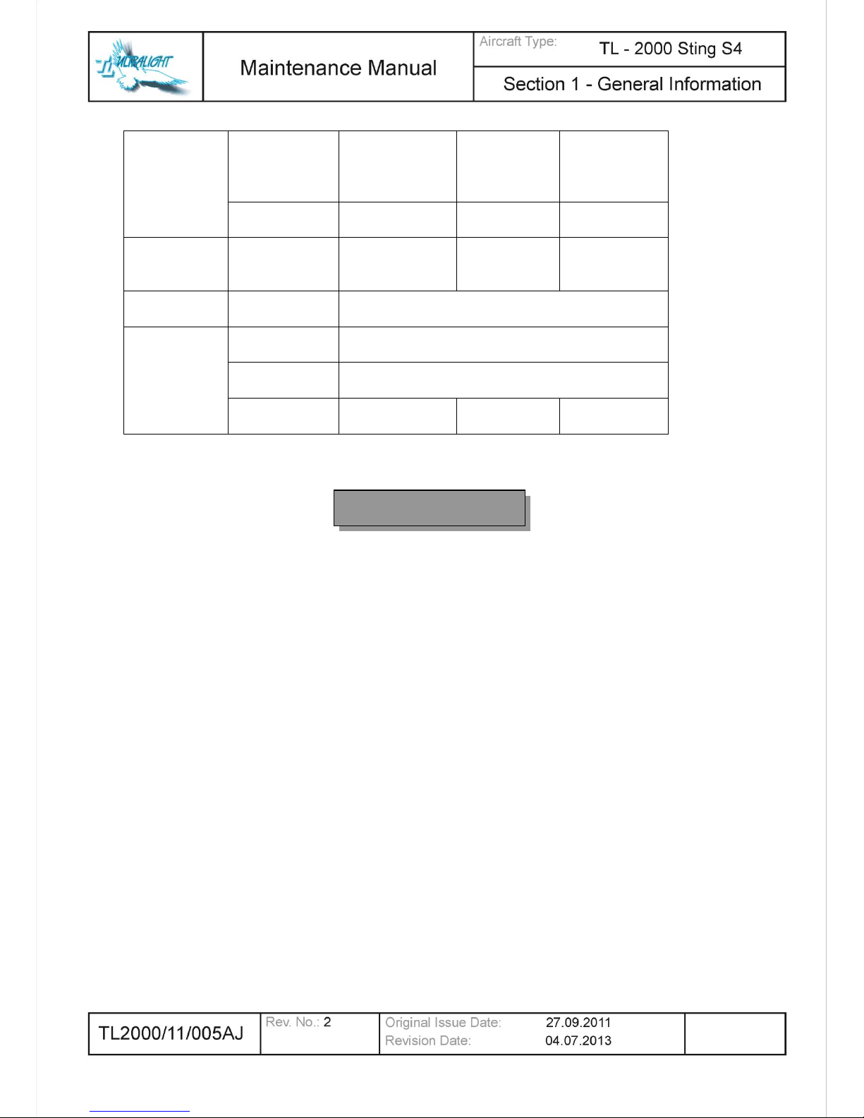
0.3 List of Revisions
The Revisions pages are updated by TL–ULTRALIGHT each time revision issued.
They contain a list of all revisions made to the Maintenance Manual since its original
issue.
Nr.
Date
Revised
pages
Type of Revision
Posted By
0
27 September 2011
None
Original Issue
1
18 March 2013
all chapters
Added additionally
information about the fuel
system, system of
electrical controlled flaps
and foot pedals. Updated
list of disposable
replacement parts
TL-ULTRALIGHT
2
4 July 2013
1-11
Propeller type update
TL-ULTRALIGHT

1-1
1. GENERAL INFORMATION
1.1 Introduction
Section 1 contains general information regarding manual organization, descriptive
data, abbreviations, the Master Equipment List, ‘feed-back’ forms for the aircraft and
this manual as well as current warranty information.
This manual is written to conform to the ASTM F2483, Maintenance and the
Development of Maintenance Manuals for Light Sport Aircraft. Maintenance and
operation of major components, engine, emergency parachute system, propeller,
avionics or other installed equipment is provided in the appropriate manufacturer
manuals which are included with the aircraft. Any conflicts in this manual should be
superseded by the appropriate manufacturer’s manual.
1.1.1 Scope
This document defines the content and structure of the maintenance manual for the
TL Ultralight, sro Sting S4 aircraft and it’s components while operated as light sport
aircraft.
1.1.2 Safety
TL Ultralight, sro cannot address all of the safety concerns associated with the use of
this document. It is the responsibility of the user of this document to establish
appropriate safety and health practices and to determine the applicability of any
regulatory limitations prior to use.
1.1.3 Referenced Documents
ASTM Standards:
F 2245 Specification for Design and Performance of a Light Sport Airplane
F 2295 Practice for Continued Operational Safety Monitoring of a Light Sport Airplane
Federal Standards:
14 CFR Part 21.190 Issue of a Special Airworthiness Certificate for a Light-Sport
Category Aircraft
14 CFR Part 43 Maintenance, Preventive Maintenance, Rebuilding, and Alteration
14 CFR Part 65 Certification: Airmen Other Than Flight Crewmembers

1-2
1.1.4 Definitions
14 CFR—Code of Federal Regulations Title 14 Aeronautics and Space also know as
the “FARs” or Federal Aviation Regulations.
100-hour inspection—same as an annual condition inspection, except the interval of
inspection is 100 hours of operation instead of 12 calendar months. This inspection is
utilized when an LSA aircraft is being used for commercial operations such as flight
instruction or rental, or both.
Alteration—any change to the airframe or aircraft component part after the initial
design and production acceptance testing by TL Ultralight, sro to the applicable
ASTM standards that is not described in the TL Ultralight, sro maintenance manual.
Annual condition inspection—detailed inspection accomplished once a year on an
LSA aircraft in accordance with instructions provided in the maintenance manual.
The purpose of the inspection is to look for any wear, corrosion, damage or
conditions of use that would cause an aircraft to not be in a condition for safe
operation.
A&P—airframe and power plant mechanic as defined by 14 CFR Part 65.
FAA—United States Federal Aviation Administration.
Heavy maintenance—any maintenance, inspection, or repair, that TL Ultralight, sro
has designated that requires specialized training, equipment, or facilities.
Line maintenance—any repair, maintenance, scheduled checks, servicing,
inspections not considered heavy maintenance that is approved by TL Ultralight, sro
and is specified in TL Ultralight, sro’s maintenance manual.
LSA (light sport aircraft)—aircraft designed in accordance with ASTM standards
under the jurisdiction of Committee F37 Light Sport Aircraft.
LSA repairman inspection—U.S. FAA-certificated repairman (light sport aircraft) with
an inspection rating as defined by 14 CFR Part 65, authorized to perform the annual
condition inspection on experimental light sport aircraft, or an equivalent rating issued
by other civil aviation authorities. Experimental LSA aircraft do not require the
individual performing maintenance to hold any FAA airman certificate in the U.S.
LSA repairman maintenance—U.S. FAA-certificated repairman (light sport aircraft)
with a maintenance rating as defined by 14 CFR Part 65, authorized to perform line
maintenance on aircraft certificated as special LSA aircraft. Authorized to perform
the annual condition/100-h inspection on an LSA, or an equivalent rating issued by
other civil aviation authorities.
Maintenance manual (AMM)—manual provided by an TL Ultralight, sro that specifies
all maintenance or repairs authorized by TL Ultralight, sro.

1-3
Major repair or maintenance—any repair or maintenance for which instructions to
complete the task are excluded from the maintenance manual supplied to the
consumer are considered major.
Manufacturer—any entity engaged in the production of an LSA or component used
on an LSA.
Minor repair or maintenance—any repair or maintenance for which instructions are
provided in the TL Ultralight, sro maintenance manual are considered minor.
Modification—any change to the airframe or aircraft component part after the initial
design and production acceptance testing by TL Ultralight, sro to the applicable
ASTM standards that is not described in the TL Ultralight, sro maintenance manual.
Overhaul—maintenance, inspection, or repair that is only to be accomplished by the
TL Ultralight, sro or a facility approved by the original manufacturer of the product.
Overhaul facility—facility specifically authorized by the FAA or TL Ultralight, sro or
component manufacturer to overhaul the product originally produced by that
manufacturer.
Repair facility—facility specifically authorized by the FAA or TL Ultralight, sro or
component manufacturer to repair the product originally produced by that
manufacturer.
1.1.5 Maintenance and Repair
Inspection or Repair, —Each of the inspections or repairs outlined in the
maintenance manual specifically list:
(1) Recommended special tools to accomplish the task, if any
(2) The parts needed to perform the task, if any
(3) Type of maintenance, line (L), heavy (H), or overhaul (OV)
(4) The level of certification needed to accomplish the task, owner (ON), (light sport
aircraft) inspection (RI), (light sport aircraft) repairman (RM), FAA approved A&P
(A&P), FAA or TL Ultralight repair station,
(5) Detailed instructions and diagrams if needed to perform the task, and
(6) Confirmation by signature to verify the task was accomplished properly.
Repairs and Alterations—TL Ultralight, sro may refer to other repair and alteration
manuals such as the FAA’s AC for the detailed instructions to accomplish tasks
outlined in the maintenance manual.
Level of Certification—When listing the level of certification needed to perform a task,
TL Ultralight, sro shall use one of the following descriptors.
Owner (ON)—Items that can be expected to be completed by a responsible owner
who holds a pilot certificate but who has not received any specific authorized training.

1-4
FAA regulations authorize SLSA aircraft owners who hold at least a sport pilot
certificate to perform maintenance as outlined in 14 CFR Part 43.
LSA Repairman Inspection (RI)—Items that can be expected to be completed on an
ELSA by a responsible owner, which holds an FAA repairman certificate (light sport
aircraft), with an inspection rating or equivalent.
A&P (A&P)—Items that can be expected to be completed by a responsible individual
who holds an FAA mechanic certificate with airframe or power plant ratings, or both,
or equivalent.
Task Specified—Items that can be expected to be completed by a responsible
individual who holds either a mechanic certificate or a repairman certificate and has
received task specific training to perform the task.
Therefore the symbol (ON) indicates a maintenance function that can be performed
by an owner or higher skilled level. The symbol (A&P) indicates maintenance to be
performed by an A&P or a Repair Station. Indicated at each task by the following
designation(s); (ON-RI-RM-A&P) and level of maintenance, (L-H-OV) see 1.1.6.
Task Not Specified—The aircraft is to be maintained, serviced and repaired in
accordance with this manual and the equivalent maintenance manual provided by the
manufacturer of all other components not manufactured by TL Ultralight, sro. In the
absence of specific instructions for a repair in one of the above mentioned
maintenance manuals, and where such repairs are not restricted by these manuals or
listed as Overhaul, Alteration, Modification or Major Repair, such repairs may be
completed by an FAA qualified A&P mechanic. Such repairs must be coordinated
with the TL Ultralight U. S, Field Technical Director, in accordance with standard
maintenance practice described by FAA Advisory Circular 43.13 and use all available
resources including exploded parts views for guidance.
1.1.6 Line Maintenance and Repairs (L)
Authorization to Perform—The holder of an LSA repairman certificate with either an
inspection or maintenance rating is generally considered the minimum level of
certification to perform line maintenance of TL Ultralight LSA aircraft. The examples
listed below are not considered as restrictions against the performance of such tasks
by an owner who is authorized to perform said task by the FAA.
Typical Tasks Considered as Line Maintenance Include:
1. 100-hour inspection,
2. Annual condition inspection,
3. Servicing of fluids,
4. Removal and replacement of components for which instructions are provided in
the maintenance manual.
5. Repair of components and structure for which instructions are provided in the
maintenance manual and which do not require additional specialized training.
6. Compliance with a TL Ultralight, sro service directive when the repairman is listed
as an authorized person to accomplish the work described.
1-5
1.1.7 Heavy Maintenance and Repairs (H)
Authorization to Perform—The holder of an FAA mechanic certificate with airframe or
power plant rating(s), or both, or an LSA Repairman maintenance that has received
additional task specific training for the function to be performed is generally
considered the minimum level of certification to perform heavy maintenance of TL
Ultralight, sro LSA aircraft.
Typical Tasks Considered as Heavy Maintenance include:
Removal and replacement of components for which instructions are provided in the
maintenance manual or service directive instructions, such as:
Complete engine removal and reinstallation in support of an engine overhaul
or to install a new engine,
Remove and replacement of engine cylinders, pistons, or valve assemblies, or
a combination thereof,
Primary flight control cables/components,
Landing gear assemblies.
Repair of components for which instructions are provided in the maintenance
manual or service directive instructions,
Structural repairs of components or aircraft structure, or both, for which
instructions are provided in the maintenance manual or service directive
instructions.
1.1.8 Overhaul (OV)
Authorization to Perform—Only TL Ultralight, sro or the FTD may overhaul an LSA
component or they may authorize the overhaul of an LSA component to be
performed by a competent facility. No FAA certification is required to be an LSA
approved overhaul facility.
Overhaul Manual—A separate overhaul manual in addition to the TL Ultralight, sro
maintenance manual is required to perform the overhaul of an LSA aircraft or LSA
aircraft component.
Typical components that are overhauled include:
1. Engines,
2. Carburetors/fuel systems,
3. Starters/alternators/generators,
4. Instruments,
5. Propellers
6. Ballistic parachute systems.

1-6
1.1.9 Alteration, Modification or Major Repair
Any alteration, modification or major repair made to TL Ultralight, sro aircraft after the
initial design and production acceptance testing to applicable ASTM standards, initial
airworthiness inspection and sale to a consumer must be evaluated by TL Ultralight
relative to the requirements of the applicable ASTM design and production
acceptance specification(s) as well as the aerodynamic, structural, electrical, or flight
safety conditions.
No changes may be made to any TL Ultralight, sro aircraft without prior written
approval of TL Ultralight, sro. Any changes made without TL Ultralight, sro written
approval will void the aircraft airworthiness certificate.
TL Ultralight, sro may authorize another TL Ultralight, sro approved entity to perform
the evaluation of an alteration, modification or major repair who shall provide a
written affidavit that the aircraft being altered will still meet the requirements of the
applicable ASTM design and performance specification after the alteration.
TL Ultralight, sro or another TL Ultralight approved entity that performs the evaluation
shall provide written instructions and diagrams on how, who, and the level of
certification needed to perform the alteration, modification or major repair.
The instructions must be approved by TL Ultralight, sro or the local FTD and must
include ground and flight testing that complies with the original ASTM production
acceptance testing standard, as appropriate, to verify the alteration, modification or
major repair was performed correctly and the aircraft is in a condition for safe
operation.
TL Ultralight, sro or another TL Ultralight approved entity that performs the evaluation
shall provide information to the owner of the aircraft for the documentation of the
alteration, modification or major repair in the aircraft’s records.
1.1.10 Task-Specific Training
TL Ultralight, sro may require type-specific training in order to accomplish a task in
either the maintenance manual or in an authorization for a major repair, maintenance,
or alteration. The FAA does not give approval to these task-specific training
programs for SLSA. TL Ultralight, sro may specify any task-specific training it
determines is appropriate to accomplish a task.
Examples of task-specific training include:
1. Engine manufacturer heavy maintenance or overhaul school, or both,
2. Instrument installation or repair course
3. Parachute manufacturer replacement course
4. Aircraft manufacturer course.

1-7
1.1.11 Safety Directives
An SLSA aircraft may have a Safety Directive issued against an aircraft or
component part by the manufacturer. TL Ultralight, sro will issue any directive as
outlined in the applicable ASTM continued airworthiness specification.
SLSA and components installed on SLSA’s do not have Airworthiness Directives
issued against them. If an AD is issued against a type-certificated product that may
be incorporated into special light sport aircraft, TL Ultralight, sro will issue a safety
directive in accordance with ASTM Standard F 2295 to provide instructions on how to
address the safety defect outlined in the AD on component in the specific SLSA.
TL Ultralight, sro will provide applicable instructions to comply with any safety
directive, which will include:
1. A list of the tools needed to accomplish the task,
2. A list of the parts needed to perform the task,
3. Type of maintenance, line, heavy, overhaul,
4. Certification level needed to accomplish the task, RI, RM, A&P.
5. Detailed instructions and diagrams as needed to perform the task,
6. Method to test/inspect to verify the task was accomplished properly.
7. Service directives are considered mandatory tasks in order to maintain a condition
of safe operation and compliance with the applicable original ASTM design
specification. Service directives are not considered mandatory for experimental
LSA’s in the United States.
1-8
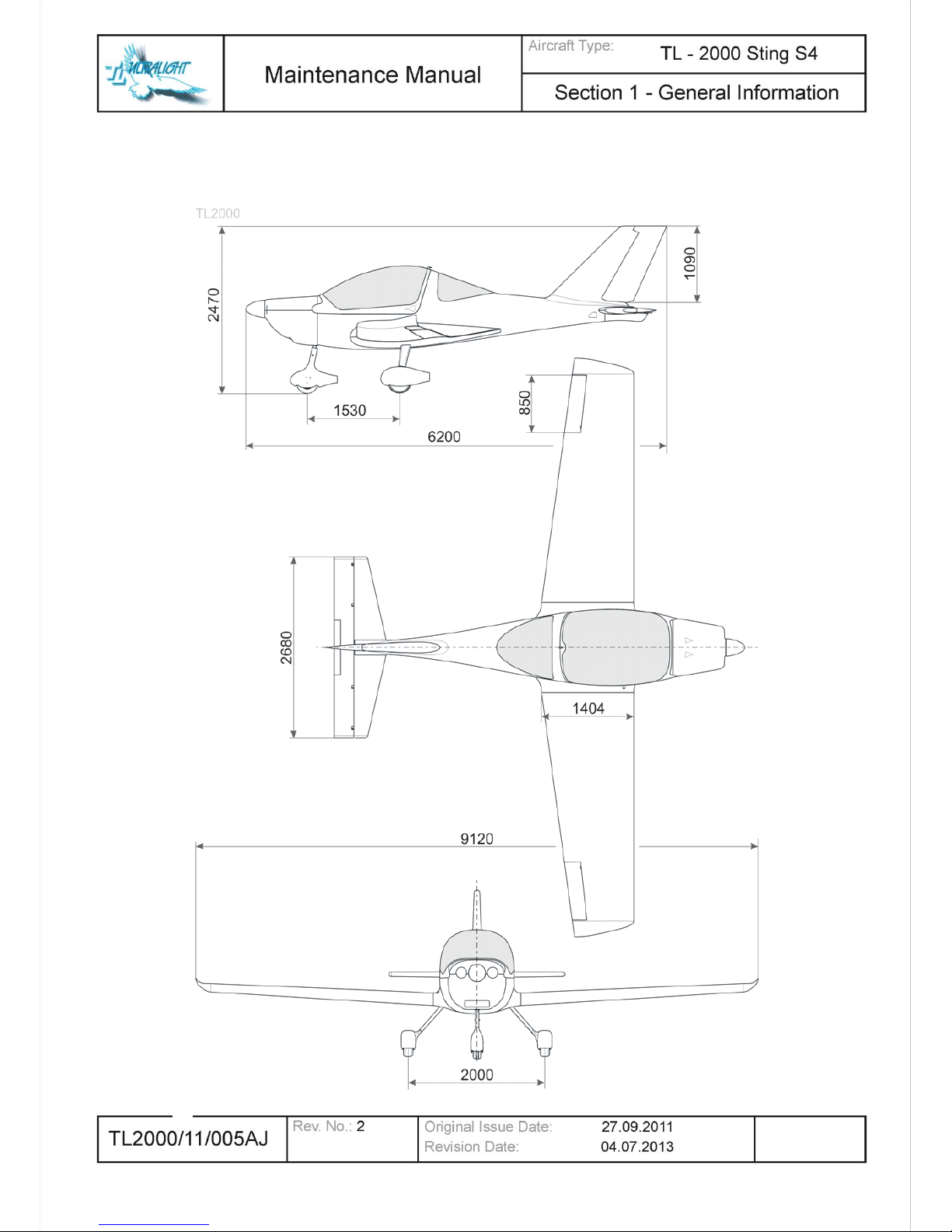
1.1.12 Views, dimensions
All dimensions are
in millimeters
1-9
1.1.13 Aircraft Specification
The TL-2000 Sting S4 is a full three axis, low wing, two place, side-by-side seating,
tricycle landing gear aircraft with a steerable nose wheel. The primary aircraft
structure is carbon fiber and fiberglass UV resistant reinforced laminate with an inner
foam core creating a ‘sandwich’ layered construction between each ply.
Various options are available such as the Rotax 912ULS, tinted canopies and other
avionics or interior selections. Therefore your aircraft may vary from the descriptions
in this manual. Please check with your local dealer if you have any specific questions
not addressed here.
Basic dimensions
Length: 20 ft. 4 in.
Cabin width: 44 in.+
Wing span: 29 ft. 11 in.
Height: 6 ft. 4 in.,
Areas
Wing: 119,479 ft
2
Flap: 18.6 ft
2
Aspect ratio: 7.26
Glide ratio: 12:1
Gross weight: 1320 lbs
1.1.14 Engine Specification
4-cylinder, 4-stroke liquid/air cooled engine with opposed cylinders, dry sump forced
lubrication with separate oil tank, automatic adjustment by hydraulic valve tappet, 2
carburetors, mechanical fuel pump, electronic dual ignition, electric starter, propeller
speed reduction unit.
For actual and complete information see the Maintenance Manual for ROTAX
Engine Type 900 Series supplied with the aircraft.
CAUTION
1-10
Operating speeds and limits:
Engine Type
Rotax 912 UL
Rotax 912 ULS
Speed:
Take-off speed
5800 1/min (5
min.)
5800 1/min (5
min.)
Maximum continuous speed
5500 1/min
5500 1/min
Idle speed
ca. 1400 1/min
ca. 1400 1/min
Performance (ISA): (International Standard Atmosphere)
Take-off performance
59,6 kW (80 BHP)
at 5800 1/min
73,5 kW (100
BHP) at 5800
1/min
Maximum continuous performance
58 kW at 5500
1/min
69 kW at 5500
1/min
Acceleration:
Limit of engine operation at zero gravity
and in negative ˝g˝ conditions, max
5 seconds at max.
-0,5 g
5 seconds at max.
-0,5 g
Reduction ratio:
Crankshaft : propeller shaft
2,27 : 1
2,43 : 1 (optional)
2,43 : 1
Oil pressure:
Maximum
7 bar
7 bar
Minimum
0,8 bar (12 psi)
(below 3500 rpm)
0,8 bar (12 psi)
(below 3500 rpm)
Normal
2,0 ÷ 5,0 bar (29 ÷
73 psi) (above
3500 rpm)
2,0 ÷ 5,0 bar (29 ÷
73 psi) (above
3500 rpm)
Oil temperature:
Maximum
140°C (285°F)
130°C (266°F)
Minimum
50°C (120°F)
50°C (120°F)
Normal operating temperature
ca. 90 ÷ 110°C
(190 ÷ 230°F)
ca. 90 ÷ 110°C
(190 ÷ 230°F)
Cylinder head temperature:
Maximum – reading at observation point of
the hotter cylinder head, either no. 2 or no.
3
150°C (300°F)
135°C (284°F)
Engine start, operating temperature:
Maximum
50°C (120°F)
50°C (120°F)
Minimum
- 25°C (- 13°F)
- 25°C (- 13°F)
Fuel pressure: (Current fuel pump)
Maximum
0,4 bar (5,8 psi)
0,4 bar (5,8 psi)
Minimum
0,15 bar (2,2 psi)
0,15 bar (2,2 psi)
1-11
1.1.15 Propeller Specifications
For actual and complete information read the Maintenance Manual for DUC
Propeller supplied with the aircraft.
Propeller Manufacturer
DUC Hélices company
Propeller Model Number
Three-blade SWIRL, Right
Number of Blades
3
Propeller Diameter
1660 mm (65.51 in)
Propeller Type
˝Ground Adjustable˝ - variable
pitch
Recommended Blade Pitch Angle Setting (
Rotax 912 UL)
20°
Recommended Blade Pitch Angle Setting (
Rotax 912 ULS)
24°
1.1.16 Structural Materials
Non-metal materials:
No.
Material Description
Supplier
Supplier article
number
1
Epoxy resin L-285
Skolil kompozit s.r.o.
2 Hardener 285
Skolil kompozit s.r.o.
3 Hardener 287
Skolil kompozit s.r.o.
4
Hardener C
Havel Composites CZ
s.r.o.
5
Epoxy flokes
BAUMWOLLEFLOCKEN
Skolil kompozit s.r.o.
L+R0025
6
Epoxy flokes GLASS
Bubbles Q-Cell 2106
Skolil kompozit s.r.o.
L+R0026
7
Helmipur 46 022
FH Technik spol. s.r.o.
146022.0110.01
8
Harter 49533
FH Technik spol. s.r.o.
149534.0324.01
9
Fiber glass fabric
SKLOTEX st. 1080
Skolil kompozit s.r.o.
112
10
Fiber glass fabric
SKLOTEX st. 0235
Skolil kompozit s.r.o.
119.1
11
Fiber glass fabric
Interglas 90070
GRM Systems s.r.o.
12
Fiber glass fabric 92110
Skolil kompozit s.r.o.
117.11
13
Fiber glass fabric 92125
Skolil kompozit s.r.o.
116.4
CAUTION
1-12
14
Fiber glass fabric 92145
UD Interglass
Skolil kompozit s.r.o.
15
Carbon fabric UD 177gr.
Skolil kompozit s.r.o.
052.39
16
Carbon fabric CT – U 175
GRM Systems s.r.o.
40045
17
Carbon fabric 41090 1K
Skolil kompozit s.r.o.
042
18
Carbon fabric 43 200 TT
kepr
Skolil kompozit s.r.o.
040.012
19
Carbon fabric 200 g/m2 –
kepr 2/2
GRM Systems s.r.o.
20011
20
Roving glass EC 12 2340
816(45)
Skloplast a.s. Trnava
21
Roving carbon T 700SC
12k-50C
Skolil kompozit s.r.o.
22
Divinycell H60
Skolil kompozit s.r.o.
3H4008000000
23
Alkamid
24
Poly JARID (Silon)
PolyPLASTY s.r.o.
VV 08197
Metal materials:
No.
Material Description
Source of mechanical properties
1
Steel 11 323
ČSN 41 1323
2
Steel 11 353
ČSN 41 1353
3
Steel 11 523
ČSN 41 1523
4
High-tensile steel 15 130.1
ČSN 41 5130.1
5
Chromium – molybdenum steel
4130
6
Stainless steel 17 153
ČSN 41 7153
7
Stainless steel EN ISO 9445
EN 10088-2
8
Aluminium alloy 42 4201.61
ČSN 42 4201.61
9
Aluminium alloy 42 4254.61
ČSN 42 4254.61
10
Bronze EN CW-617N CuZn40Pb2
ČSN EN 1412
11
Bronze EN CW-CuSn8
ČSN EN 1412
1.1.17 Aircraft and engine approved equipment
The latest list of approved equipment for TL aircraft is published at our website:
www.sting.aero/owners
Changes and additions to the master equipment list will be issued as structural,
dynamic, electrical, loading, weight/balance, and system component performance
testing and analysis is completed.
Manufacturers are encouraged to submit requests to the U. S. Field Technical
Director for additions to the equipment list. Such requests must explain proposed
benefits to our customers, documentation of all aspects of the item under
consideration, samples and anticipated effect on existing components/systems, as
well as with a written program describing the methods of both ground and flight
testing necessary for approval.
1-13
TL Ultralight must remain and retain the approval authority of any items installed in
the TL2000 Sting S4 series aircraft. Therefore the latest edition of the Master
Equipment List must be enforced as the only approved items for installation on the
aircraft without further authority. No substitutions are allowed without a proper testing
program previously approved under the written authority of TL Ultralight, sro or the U.
S. Field Technical Director.
1.1.18 List of disposable replacement parts
Type of
component
Component
Components
marking
Airplane
variant
Replacement
Filters
Air filter
Rotax 825 551
all variants
after every 300
hours
Rotax 825 711
all variants
after every 300
hours
KN Filters R -
1060
all variants
after every 300
hours
Fuel filter
Gascolator ACS
10580
all variants
on condition
Oil filter
Rotax 825012
all variants
after every 100
hours
Hoses
Fuel system
hoses
FUB 386 5/11
FUB 386 6/12
FUB 386 8/14
all variants
after every 5
yaers
Engine cooling
system hoses
Rubena 402529
all variants
after every 5
yaers
Oil hoses
Rotax 956 390
all variants
after every 5
yaers
Rubber parts
Engine mount
rubber blocks
Rubena 40757 /
042757
all variants
after every 5
yaers
Carb. bracket
rubber blocks
Rubena 40795
all variants
after every 5
yaers
Ignition rubber
block
Rotax
all variants
after every 5
yaers
Wheel tires
size 400 x 100
Sting Sport,
Sting S3
on condition
size 300 x 100
Sting Sport,
Sting S3
on condition
size 15 x 6
Sting S4
on condition
size 11 x 4
Sting S4
on condition
Brake system
parts
Brake pads
DIAFRICT
2057163605590
400 x 100 mm
wheels
on condition
Brake disc
TL
400 x 100 mm
wheels
on condition
1-14
Brake system
parts
Brake pads
DIAFRICT
2057163607170
and
2057163607180
400 x 100 mm
size wheels
on condition
Brake disc
S4-350_000_00-
1
15 x 6 size
wheels
on condition
Metal parts
Metal plates
under the
engine
STING-15-2-2
all variants
after every 300
hours
Engine parts
Ignition sparks
see the current Operator´s Manual for all version of
ROTAX 900 series
Fluids
Oil
see the current Operator´s Manual for all version of
ROTAX 900 series
Cooling fluid
see the current Operator´s Manual for all version of
ROTAX 900 series
Braking fluid
DOT 4 or DOT 5
all variants
after every 2
yaers
For the current and complete information regarding list of disposable
replacement engine and propeller parts see the Maintenance Manual for
ROTAX Engine Type 900 Series and the Manual for Propeller supplied with the
aircraft.
1.1.19 Weight and Balance Information
Section includes the allowed center of gravity positioning and weight ranges and
center of gravity position determination procedure allowing safe aircraft operating.
All aircraft are structurally and aerodynamically engineered for certain load conditions
which result from specific weights and forces anticipated to occur in normal
operations within the specified flight envelope. An Aircraft’s handling qualities and
structural integrity may be seriously compromised if the weight and balance limits are
exceeded in normal operations.
It is the pilot’s responsibility to make sure the weight and balance limits are not
exceeded as to weight, its location, distribution and security prior to any flight.
Definitions:
Arm: The horizontal distance expressed in inches from the reference datum plane to
the center of gravity (CG) of an item or location along the fuselage.
CAUTION

1-15
Units of measurements and weights must be consistent for each set of
calculations and in the same system of units, i.e., pounds and inches, or
kilograms and centimeters.
Ballast: A specific amount of weight attached in a specific location, which can be
temporarily or permanently installed in an aircraft, to help bring its Center of Gravity
within the required limits. If temporary ballast must be used for certain operations, the
exact amount and its location must be placarded on the instrument panel within clear
view of the pilot. The use of Ballast increases Empty Weight and reduces Useful
Load.
Basic Empty Weight: The standard empty weight plus the weight of any additionally
installed or optional equipment.
Basic Empty Weight Center of Gravity. The c.g. of an aircraft in its basic empty
weight condition, and is an essential part of the weight and balance record.
Center of Gravity (CG): A point along an aircraft’s longitudinal axis at which all the
loads and forces are perfectly concentrated and balanced. It is computed by dividing
the total moment by the total weight of the airplane. Its distance from the reference
datum is found by dividing the total moment by the total weight of the airplane.
(Total Moment / Total Weight = Center of Gravity)
Center of Gravity Arm is the arm obtained by adding the airplane's individual
moments and dividing the sum by the total weight.
Center of Gravity Limits are the extreme forward and aft center of gravity locations
(limits) within which the airplane must be operated at any given weight.
Center of Gravity Range: The horizontal distance, along an aircraft’s longitudinal
axis, within which an aircraft has been found to be fully maneuverable at all specified
design speeds, weights and loading configurations.
Datum: A convenient vertical reference plane along the longitudinal axis of an
aircraft from which all horizontal measurements are taken.
Installed Equipment: All optional accessories and equipment permanently installed
on an airframe or engine at the time of weighing. These items must be included in
the “Installed Equipment List” resulting in the Basic aircraft weight. Additions and
deletions must be noted in the list each time they are made and new Weight and
Balance calculations performed to determine the magnitude and effect of weight
change. Ballast, if permanently installed, must also be listed.
NOTE

1-16
Maximum and Minimum Weights: Due to balance, structural and aerodynamic
considerations, maximum, or minimum, weights for certain locations on the aircraft
are specified. For example, the pilot’s minimum (100Lbs) and maximum (240Lbs)
weight is be specified for some operations. The same is true for baggage, cargo,
fuel, and any other disposable or variable loads.
Maximum Forward and Maximum Aft C.G. Locations: A specified forward most
and rear most Center of Gravity location, along the aircraft longitudinal axis. These
Center of Gravity location limits are expressed in inches from a convenient reference
(forward tip of the propeller spinner) on the aircraft.
Reference or Datum Plane: An imaginary vertical plane located on the forward tip of
the propeller spinner from which all horizontal distances are measured for balance
purposes.
Standard Empty Weight: The weight of a standard airplane, including unusable
fuel, full engine operating fluids, and full engine oil reservoir.
Station: A vertical location along the airplane fuselage horizontal axis given in terms
of the distance from the reference datum plane.
Tare: The weight of chocks, blocks, stands, etc. used when weighing an
airplane, and is included in the scale readings. Tare is deducted from the scale
reading to obtain the actual (net) airplane weight.
Useful Load: The total amount of weight available for pilot, passengers, baggage,
cargo and in-flight usable fuel. The difference between the maximum ramp weight
and the basic empty weight. (Maximum Ramp Weight – Basic Empty Weight =
Useful Load) The useful load will be reduced by the installation of additional
equipment.
Weight: Actual individual weight of each item such as airframe, crew, fuel, baggage,
cargo, etc. in pounds or kilograms
Empty Weight: The actual weight of the individual aircraft, including the structure,
power plant, fixed equipment, any fixed ballast, unusable (in-flight) fuel, and coolant.
Original Empty Weight is determined by actually weighing each new aircraft before it
is flown.
Any time a Major Alteration, Modification or Repair (WHICH MUST BE APPROVED
IN WRITING BY THE MANUFACTURER.) is performed on the aircraft; a new Empty
Weight must be determined by either weighing the aircraft again, or by accurate
calculation of the weight changes and their effect on Empty Weight Center of Gravity
(EWCG) location.

1-17
Major Alteration or Modification results from the addition, deletion, or redistribution of
existing equipment and accessories, or from a repair which results in a significant
increase of weight of the airframe or engine. For example, addition or removal of
floats, skis, battery, radios, installation of a additional fuel tank(s) or engine change,
painting the airframe, installation of heavier wheels and tires, etc.
Maximum Gross Weight: The maximum total weight for which an aircraft’s
structure and performance have been approved for normal operations by its
manufacturer. It is the maximum weight (Empty Weight plus useful load) at which an
aircraft can be safely operated. Maximum Takeoff Weight must never exceed the
published Gross Weight.
Useful Load: The difference between the maximum ramp weight and the basic
empty weight. Maximum Ramp Weight – Basic Empty Weight = Useful Load The
total amount of weight available for pilot, passengers, baggage, cargo and in-flight
usable fuel.
Moment: The product of the weight of an item multiplied by its arm.
(Weight x Arm = Moment)
Loading Chart: Used to calculate the actual Center of Gravity location of a ready to
fly aircraft. Care must be taken not to exceed the Maximum/Minimum Weight and
Balance Limits stipulated for the aircraft. These limits are determined by structural,
stability and control considerations throughout the aircraft speed range.
Procedure:
All permanent equipment, options, and accessories should be installed on the aircraft
prior to weighing. All equipment options and accessories installed in the aircraft must
be listed on the “Installed Equipment List”. That list becomes part of Weight and
Balance Documents.
Be sure to remove any loose equipment, tools, etc. from the aircraft prior to weighing.
Sometimes it is necessary to adjust or reduce fuel, cargo, or passenger weights to
remain at or below Maximum Allowable Gross Weight. Temporary or permanent
ballast is sometimes necessary to bring the CG within specified limits. However, the
Maximum Allowable Gross Weight should not be exceeded under any circumstances
The fuel tank should be empty except for unusable fuel. If the fuel tank is not empty,
then the exact amount of usable fuel in the tank must be determined. Usable fuel
weight and its moment must be deducted from the Empty Weight calculations before
EWCG can be accurately determined.
Oil and coolant tanks and reservoirs must be properly filled before weighing. These
and any other liquids necessary for normal operations are considered part of an
aircraft’s empty weight.
1-18
For best results, weigh indoors. The scales must be calibrated correctly and must be
set on level ground.
Any equipment placed on the scales when weighing the aircraft, such as chocks or
blocks, should be weighed separately and the weight deducted from the scale
reading.
Measurements for the exact horizontal distance from Datum plane to center of
spindles of all wheel axles are included. These are recorded as measurements on
“Empty Weight and Balance Calculations”
The aircraft must be weighed in a level flight attitude, both longitudinally (front to
back) and laterally, as shown in the as shown in the Moment Arm Drawing Data
Sheet.
Place a scale under each wheel of aircraft for all future weighing. If only one scale is
used, be sure to level the wheels not being weighed before taking the scale readings.
Remember, the aircraft must be in proper level flight attitude to ensure accuracy.
Empty weight center of gravity calculations
Complete each horizontal line of calculations by multiplying Weight from the scale by
the Arm to find the Moment.
Total the Weight and Moment columns.
Divide the Total Empty Moment by the Total Empty Weight to determine the Empty
Weight CG location, from the Datum plane
In the example the EWCG is 80.83 inches aft of Datum. This distance is also known
as the Empty Weight Arm.
Typical empty weight calculations for the Sting aircraft
ITEM
WEIGHT
ARM
MOMENT
NOSE WHEEL
152
32.8”
4986
LEFT GEAR
327
94.2”
31130
RIGHT GEAR
326
94.2”
31035
TOTALS
805 83.4
67151
Therefore the aircraft Empty Weight Center of Gravity (EWCG) Location =
67151 (Total Moment) / 805 (Empty Weight) = 83.4 inches
aft of Datum Plane

1-19
Loaded weight and balance calculations
Complete the Loaded CG calculations as was done in the Sample Weight CG Chart.
The Empty Weight, the Empty Weight Arm, and the Empty Moment are shown in the
Loading Chart Weight and Balance Work Sheet.
Write in the actual Fuel weight for each tank location for your aircraft load condition.
Fuel weight is calculated at 6 pounds per U.S. gallon. The maximum weight for the
Main fuel tank at 20.5 gallons is 120 pounds. If installed, the maximum weight for the
Wing aux tanks at 6 gallons each side, 12 gallons total, is 72 pounds. Multiply the
fuel weight times the Arm shown in each row to obtain the moment for each tank
Write in the actual weight of Pilot1 and Pilot2, in the case of two occupants. Be sure
not to exceed the individual maximum recommended weights for the seat load.
Multiply the occupant weight times the Arm shown in each row to obtain the moment
for each seat location.
Write in the actual weight of the baggage in all three locations, pilot side storage,
copilot side storage and aft deck area. Multiply the total baggage weight times the
Arm shown in the row to obtain the moment for the baggage.
Total the weights, including the empty aircraft weight which should not exceed 1320
pounds.
Total all the moments, including the empty aircraft moment.
Divide the total moment by the total weight. This is the current CG which should be
between 80.2 and 86.7 inches from the Datum plane for the aircraft to be within its
weight and balance for this flight loading.
Complete this chart for each of critical test loading conditions to be sure that your
final Loaded CG position falls within the allowable CG limits, at all times, for all
operations.
Critical loading conditions
Each of the following eight critical loading conditions should be investigated for each
individual aircraft, along with any other possible loading condition which may affect
the Weight and Balance envelope of the aircraft. This is particularly important for
aircraft operation close to the CG limits.
Be sure the maximum individual weights and the Gross Weight are not exceeded at
any time.
 Loading...