

TLS-BocaSystems Lemur-Z, Lemur-X Operator's Manual
Lemur-Z, Lemur-X Manual
Lemur-Z/Lemur-X Kiosk Ticket Printers Operator’s Manual
Rev: 17.01.17
www.tls-bocasystems.com

1
Table of Contents Page
FCC Notice & Warranty Information 2
1.0 Unpacking the printer Introduction 3
2.0 Introduction for Lemur-Z 4
3.0 Important Safety Information 8
4.0 Installation 9
5.0 Ticket Load Procedure 14
6.0 Standard Interface Pinouts 16
7.0 Thermal Paper – Theory & Specifications 17
8.0 Maintenance 18
9.0 Troubleshooting Guide 22
Appendix A - ETHERNET PARAMETERS 24
Appendix B– INTERFACE TESTING A LEMUR 25
Appendix C – DOWNLOADING SOFTWARE COMMANDS 30
Appendix D – WINDOWS DRIVER INSTALLATION GUIDE 32
Appendix E – MAC DRIVER INSTALLATION GUIDE 46
Appendix F– SERVICE PLANS 50
Appendix G– TECHNICAL SUPPORT 51
Appendix H– LEMUR X REFERENCE DRAWING 52
Appendix I – LEMUR Z REFERENCE DRAWING 53
Appendix J – REFERENCE DRAWING FOR ROLL HOLDER 54
2.1 Introduction for Lemur-X 7
4.1 Paper Guide Installation for Lemur-Z 10
4.2 Receipt Roll Holder Installation for Lemur-Z & X 11
4.2.1 Receipt Roll Hold with Optional Low Paper Sensor 13
5.1 Ticket Width Adjustment 15
8.1 SQ Optical Sensors 18
8.2 Thermal Print Head 19
8.3 Platen 20
8.4 Cutter Assembly 21

2
FCC NOTICE
NOTE: The equipment has been tested and found to comply with the limits for a class A digital
device, pursuant to part 15 of the FCC rules. These limits are designed to provide reasonable
protection against harmful interference when the equipment is operated in a commercial environment.
This equipment generates, uses, and can radiate radio frequency energy and, if not installed and
used in accordance with the instruction manual, may cause harmful interference to radio
communications. Operation of this equipment in a residential area is likely to cause harmful
interference in which case the user will be required to correct the interference at the user’s expense.
Operation is subject to the following two conditions:
1. This device may not cause harmful interference, and
2. This device must accept any interference received, including interference that may cause
undesired operation.
NOTE: This unit was tested with shielded cables on the peripheral devices. Shielded cables must be
used with the unit to insure compliance.
WARRANTY INFORMATION
BOCA warrants the equipment manufactured and sold by it to be free from defects in material and
workmanship under normal use and service for a specified period of time. Parts damaged by
negligence or misuse (bad ticket stock, improper operating conditions, etc.) are excluded from this
warranty. Warranties for printers are 1 year from date of shipment. (NOTE: The print head is a
consumable part and is warranted for 90 days.) Spare parts carry a 90 day warranty. Tickets are
warranted, under proper storage conditions, for a period of 3 years. All warranty work is to be
performed either by BOCA or by an authorized BOCA service center. Shipping charges to the repair
center are the customer's responsibility. BOCA will pay for the equipment's return via ground service.
Please go to the link below if you have any reported issues with your new BOCA printer.
www.bocasystems.com/onlinesupportform.html
Equipment damaged in shipping should be reported immediately both to BOCA and to the shipper.
EXTENDED WARRANTY PLAN - BOCA offers extended warranty plans for all printer models. These
plans cover all parts and labor. All labor is to be performed at the BOCA facility. Equipment
damaged by misuse or negligence, including damage to print heads caused by defective ticket stock,
is excluded from this extended warranty. The customer, at its option, may request BOCA to ship
individual parts to expedite simple repair procedures. In certain cases where the customer is unable
to wait for the normal repair cycle, BOCA will ship an exchange printer within one business day after
notification by the customer. All freight charges are the responsibility of the customer.
Click here to return to > Table of Contents
3
1.0 Unpacking the Printer
The printer is shipped in a ruggedized container. Please save packing material for future use. Remove the
printer and accessories from the box and inspect for obvious damage. If damage is noticed, please report it
immediately to BOCA.
Email: cathy@bocasystems.com Tel: (561) 998-9600 Fax: (561) 998-9609
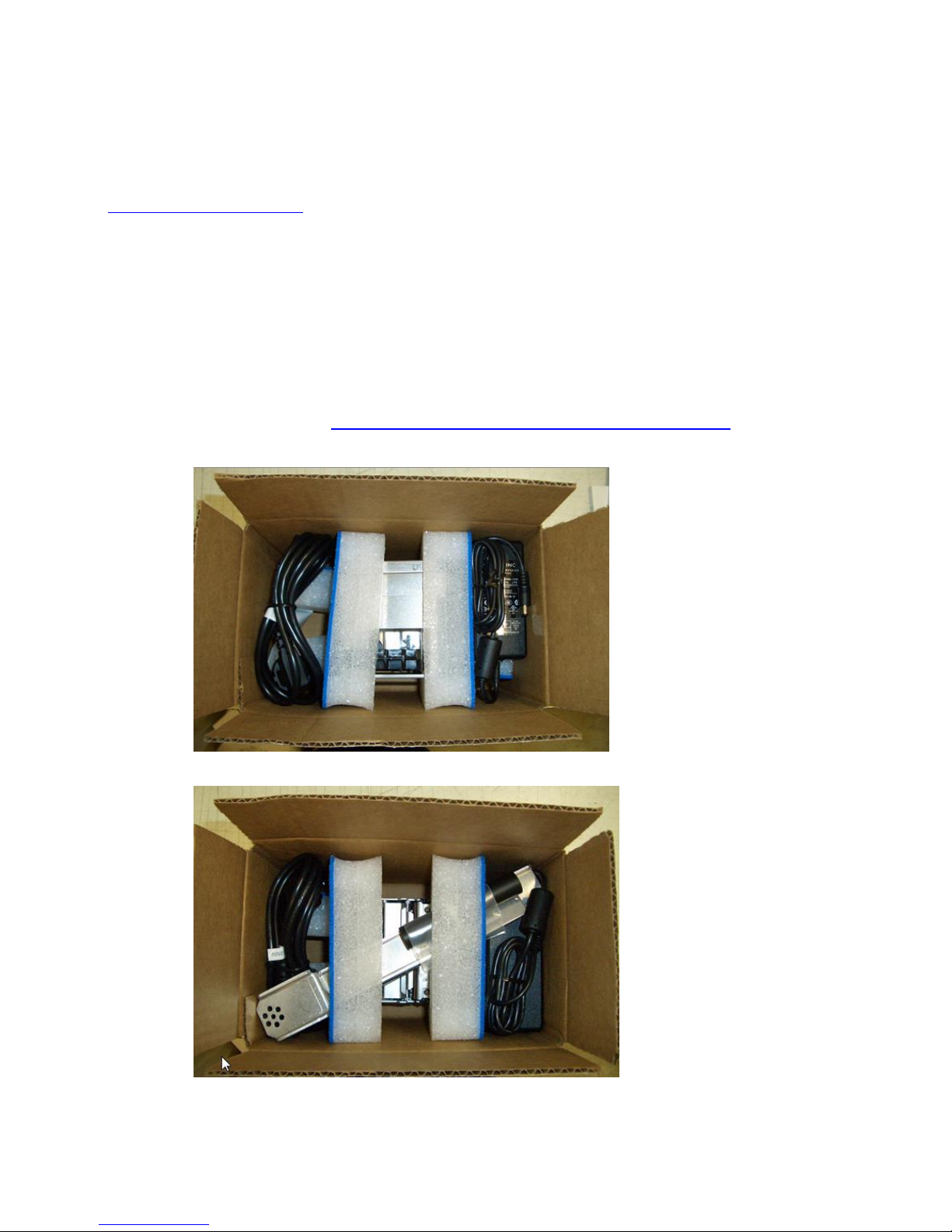
The following items should be in the box:
A) Lemur-Z or X Printer
B) 24VDC power supply
C) AC cord
D) May come with one or both of the below listed items (depending on what was ordered):
- Input paper guide (P/N 424050) for Lemur-Z printers only
or
- Receipt roll holder (P/N 424051)
E) Interface cable (optional)
F) Optional low paper sensor (see 4.2.1 Receipt Roll Holder with Optional Low Paper Sensor )
Above shows printer with Input paper guide.
Above shows printer with receipt roll holder.
4
Print Head
Presenter rollers
Retract Exit
Printout Exit
Loop area
Cutter
2.0 Introduction for Lemur-Z
The Lemur-Z is a direct thermal ticket printer with integrated cutting mechanism. This manual will provide the
user with general information regarding printer set-up, configuration and troubleshooting. Please read the
important safety information section before installation is conducted. Review the programming guide for
additional details.
The Lemur-Z series are kiosk printers designed for use with 2” (50.8mm) to 3.25” (82.5mm) rolled receipt stock
or fan folded stock with black timing mark using direct thermal printing. The following is a link to the black
timing mark specs www.bocasystems.com/ticket_specs10.html . The printer features intergraded auto cut
mechanism, easily adjustable paper guide (if equipped) and presenter with built in retract and retain function.
The print head may be easily opened to give the operator easy access to the paper path and print head for
routine maintenance.
Principle of Operation
5
PRESENTER
Print
Store printout
in loop
Cut
Present Printout
Retract into kiosk
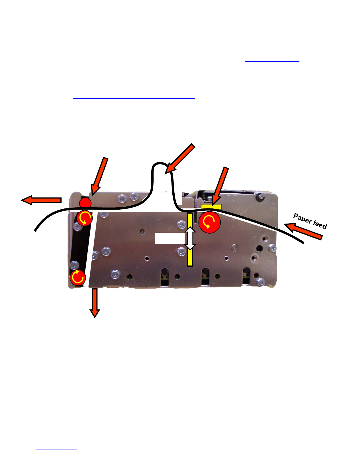
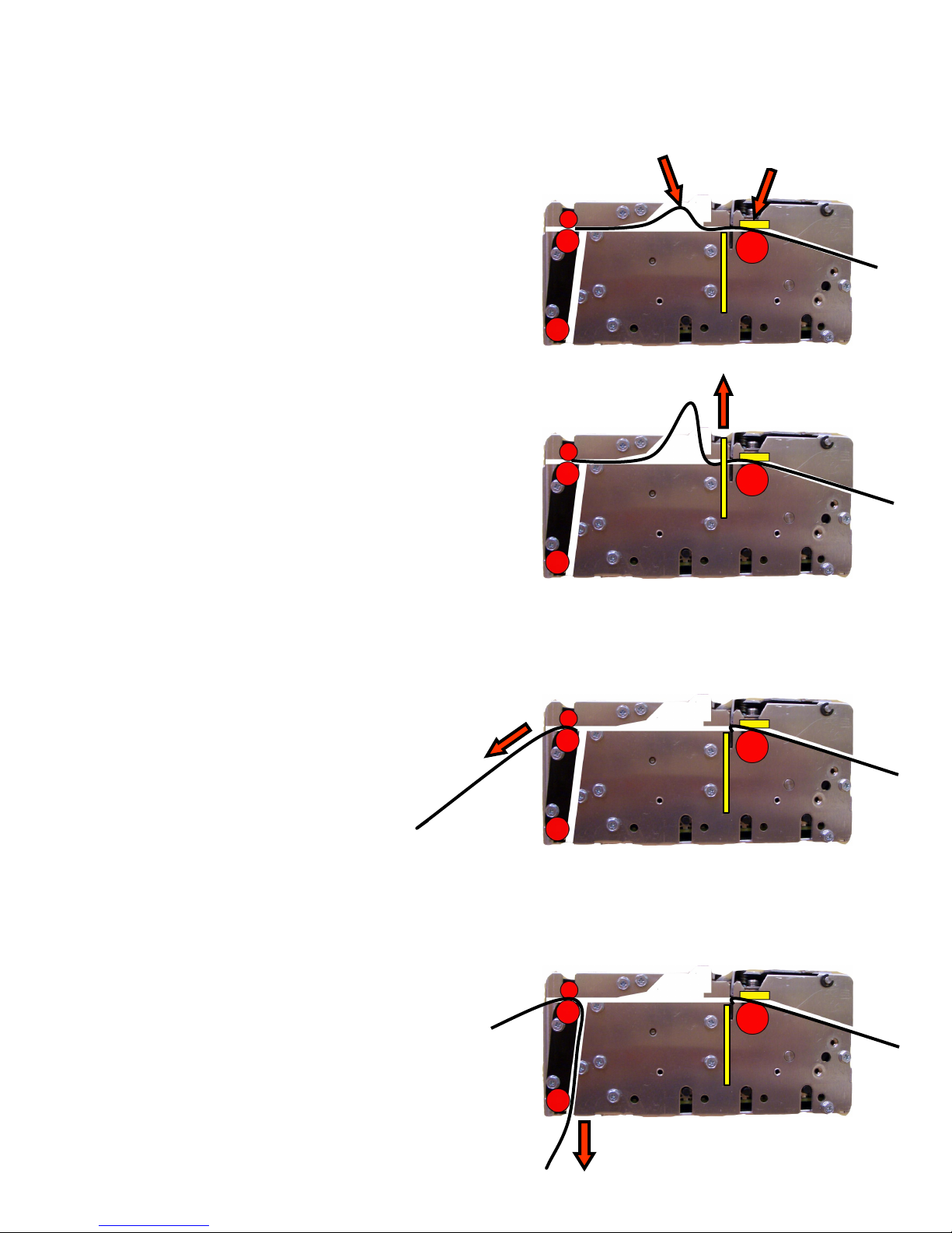
The Lemur-Z printer feature a presenter mechanism with a built in retracts and retain function. The following
illustrations provide an overview of the functionality of the various stages of printer operation.
PRINT– It handles documents of various lengths
by storing the printed paper in a loop.
CUT – It holds the printout until fully printed and
cut before presenting the completed printout to
the customer.
PRESENT – The printout is presented to the customer.
RETRACT – The retract and retain function can
retract uncollected printouts and drop them back inside
the kiosk.
6
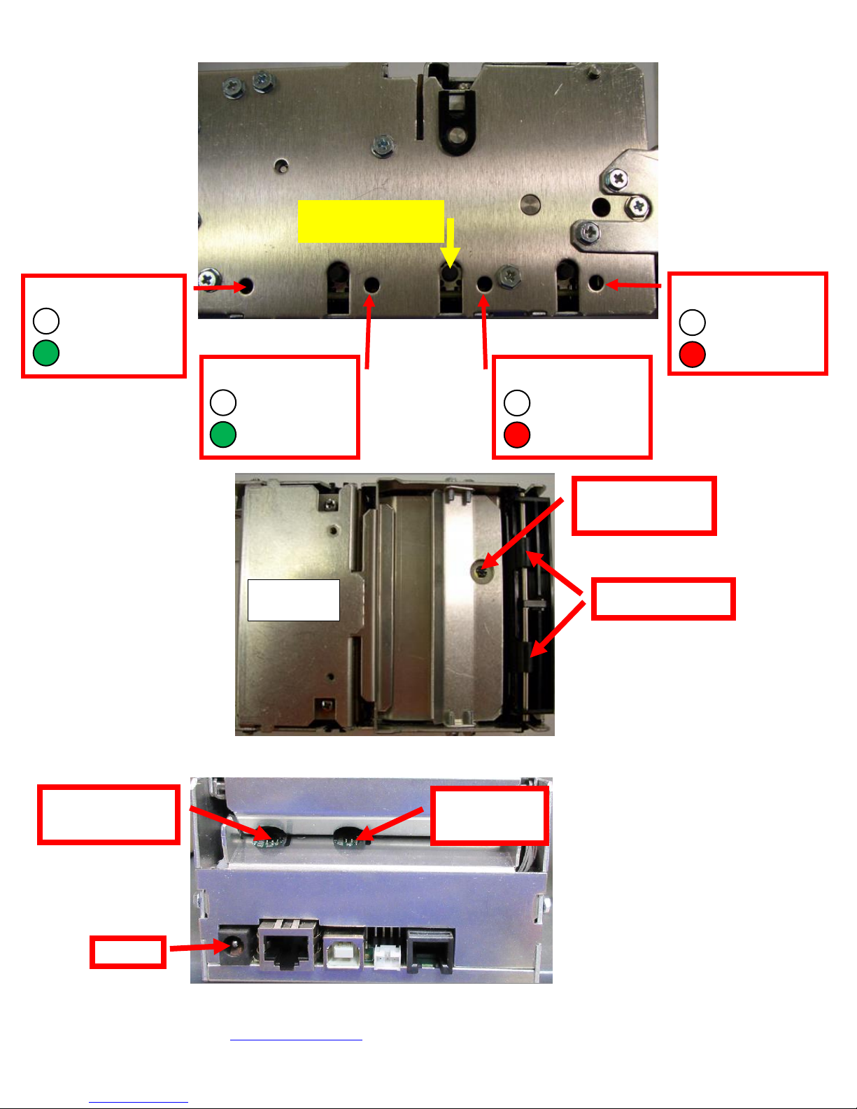
Controls & Sensors
DATA
No data received
Data received
CHECK PAPER
Has paper
No paper
PAPER JAM
No paper jam
Paper jam
Self-test button
Black timing
mark sensor
Ticket load
sensor
Head of form/
Exit sensor
Presenter rollers
Print Head
Assembly
READY
Not ready
Ready
Top View
Click here to return to > Table of Contents
7
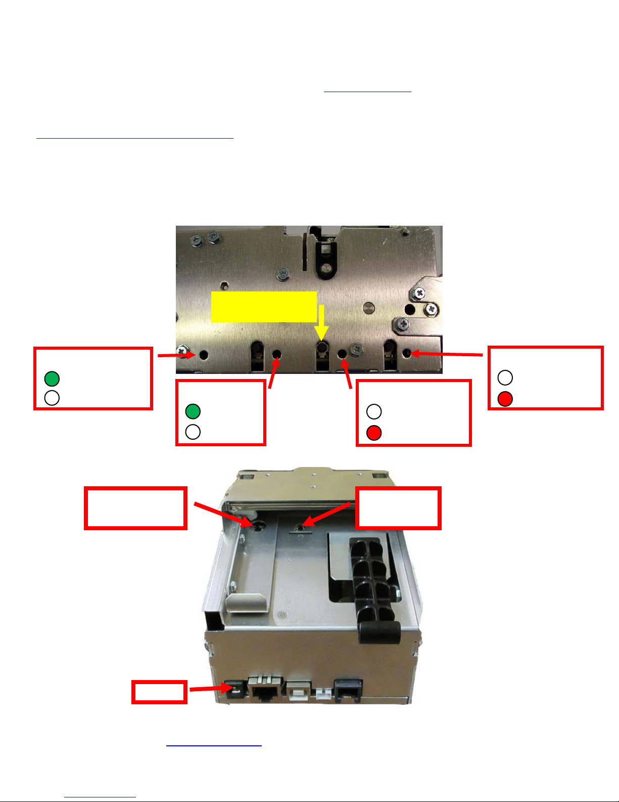
2.1 Introduction Lemur-X
DATA
No data received
Data received
CHECK PAPER
Has paper
No paper
PAPER JAM
No paper jam
Paper jam
Self-test button
READY
Not ready
Ready
Black timing
mark sensor
Ticket load
sensor
The Lemur-X is a direct thermal ticket printer with integrated cutting mechanism. This manual will provide the user with
general information regarding printer set-up, configuration and troubleshooting. Please read the important safety
information section before installation is conducted. Review the programming guide for additional details.
The Lemur-X series are kiosk printers designed for use with 2” (50.8mm) to 3.25” (82.5mm) rolled receipt stock or fan
folded stock with black timing mark using direct thermal printing. The following is a link to the black timing mark specs
www.bocasystems.com/ticket_specs10.html . The printer features intergraded auto cut mechanism and easily adjustable
paper guide.
The print head may be easily opened to give the operator easy access to the paper path and print head for routine
maintenance.
Controls & Sensors
Click here to return to > Table of Contents

8
3.0 Important Safety Information
WARNING: The appearance of this symbol indicates the proximity of an
exposed high voltage area. Please follow all directions carefully for your
personal safety. You must read the following safety information carefully
before working on the printer.
As a safety precaution, all service to the printer should be done by qualified persons with power off
and the AC cord unplugged from the printer. Following any procedure requiring the removal of covers
and/or doors, please verify that they have been properly attached and fastened prior to operating the
printer.
WARNING: "Provide an earthing connection before the mains plug is connected to the mains. And, when disconnecting
the earthing connection, be sure to disconnect after pulling out the mains plug from the mains."
WARNING: Power Cord Set: This must be approved for the country where it is used:
U.S.A. and Canada
The cord set must be UL-approved and CSA certified.
The minimum specification for the flexible cord is:
No. 18 AWG
Type SV or SJ
3-conductor
The cord set must have a rated current capacity of at least 10A.
The attachment plug must be an earth-grounding type with a NEMA 5-15P (15A, 125V) or NEMA 6-15P (15A,
250V) configuration.
United Kingdom only
The supply plug must comply with BS1363 (3-pin 13 amp) and be fitted with a 5A fuse which complies with
BS1362.
The mains cord must be <HAR> or <BASEC> marked and be of type H03VVF3GO.75 (minimum).
Europe only:
The supply plug must comply with CEE 7/7 (“SCHUKO”).
The mains cord must be <HAR> or <BASEC> marked and be of type H03VVF3GO.75 (minimum).
Denmark: The supply plug must comply with section 107-2-D1, standard DK2-1a or DK2-5a.
Switzerland: The supply plug must comply with SEV/ASE 1011.
WARNING: The appliance coupler (the connector to the unit and not the wall plug) must have a configuration for mating
with an EN60320/IEC320 appliance inlet.
WARNING: The socket outlet must be near to the unit and easily accessible.
WARNING: France and Peru only:
This unit cannot be powered from IT† supplies. If your supplies are of IT type, this unit must be powered by 230V (2P+T)
via an isolation transformer ratio 1:1, with the secondary connection point labelled Neutral, connected directly to earth
(ground).
WARNING: RJ-45 Ports. These are shielded RJ-45 data sockets. They cannot be used as standard traditional telephone
sockets, or to connect the unit to a traditional PBX or public telephone network. Only connect RJ-45 data connectors.
Either shielded or unshielded data cables with shielded or unshielded jacks can be connected to these data sockets.
Click here to return to > Table of Contents

9
4.0 Installation
The Lemur-X and Lemur-Z are designed to be mounted in a kiosk. Appendix H shows the mounting hole locations.
Prior to site preparation and installation, the printer should be powered up and run in the self-test mode.
Lay the printer flat on a counter top.
For a Lemur-Z Install the input paper guide (see page 8) or receipt roll holder (see page 9) onto the printer.
Attach the round DC connector of the 24VDC power supply into the printer.
Plug the AC cord into the 24VDC power supply. The printer will automatically power up once the AC corer
is plugged into its AC source
Wait five seconds after power up, during this time you will hear the cutter knife cycle. Begin loading tickets
through the entrance slot with a smooth motion until the printer automatically positions the ticket. See
section 5.0 Ticket Load Procedure.
After the ticket is automatically positioned (the green READY led will be illuminated), press the center TEST
button located on the control panel to print a test ticket.
When the Lemur-Z leaves the factory it is configured for us with receipt rolled stock (stock with no
black timing mark). If you will use the printer with stock that has a black timing mark then it will
need to be taken out of paper mode. See Appendix C – DOWNLOADING SOFTWARE COMMANDS to
download the appropriate software command.
o <pmd> this will configured the printer for use with ticket stock with a black timing mark.
o <pme> this will configured the printer for use with receipt stock without a black timing mark.
Verify that the printer properly works with your system by issuing a ticket through your computer system.
You may also use out customer based program to test the printer independently of your ticketing system
(see Appendix B)
You may now install the printer in its permanent location. Adequate room should be provided behind the printer for
the smooth feeding of ticket stock.
Below is a typical self-test printout
Your printout may vary depending on printer configuration and ticket stock used.
Click here to return to > Table of Contents
10
4.1 Paper Guide Installation for Lemur-Z
(P/N 424050)
Kit will include paper guide and four mounting screws.
1. The paper guide is installed onto the Lemur-Z via four mounting location.
2. Install the paper guide on the back of the printer and align the mounting holes to the above referenced
installation location. Install the four Philip 3/16” Hex head screws that were included with the paper
guide and tighten.
3. The black slider bar may be adjusted to accommodate ticket stock widths from 2” to up to 3.25”.
11
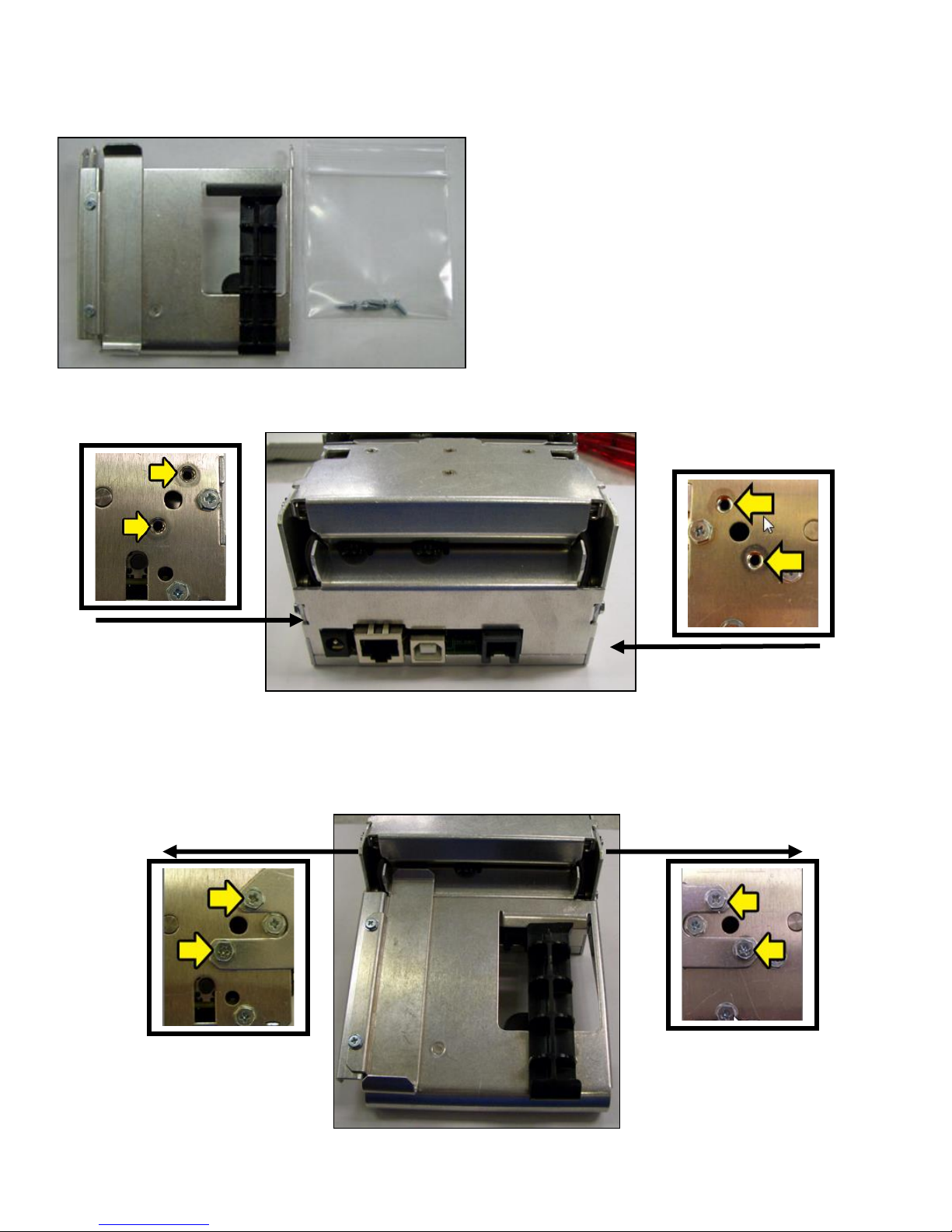
4.2 Receipt Roll Holder Installation for Lemur-X & Z
Spindle
mounting
holes
Spindle
(P/N 424051)
Kit will include mounting plate, roll holder arm, spindle, adjustable stopper and various mounting screws.
Roller holder arm may differ than what is shown in the photo
1. Attach the spindle onto the roll holder arm using the two Philip ¼” Hex head screws included with kit.
2. The Philip 3/16” Hex head screw shown in the photo below will need to be removed and will be reused.
3. Install the mounting plate onto the printer using three Philip 3/16” hex and two 3/32” Allen head screws.

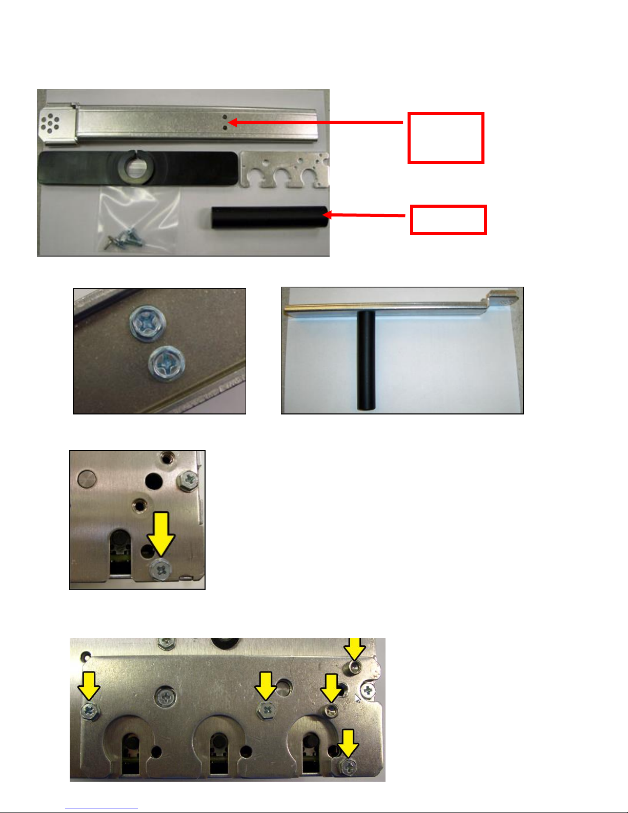
12
4. Install the roll holder arm onto the mounting plate and secure it in place with a Philip ¼” hex
Must be
completely
removed
head screw. Appendix J shows the different positions the arm may be placed in.
5. Prior to installing the receipt roll onto the roll holder arm the printer needs to be secured in
place.
6. Tear off a full turn of the paper from the new paper roll. Caution: This is important as the
outer end of the paper is usually secured to the roll with glue or other adhesive substance that
may cause paper jam or damage the print head.
7. Place the Receipt roll onto the spindle.
8. Install the adjustable stopper onto the spindle and slide into place. The stopper should not be
binding against the roller to prevent it from moving freely.
Click here to return to > Table of Contents
13
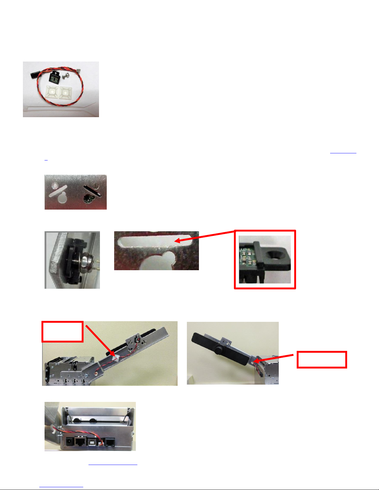
4.2.1 Receipt Roll Holder with Optional Low Paper Sensor
Hold in Arm
Cable Tie
Mount
An optional low paper sensor (P/N 424078) may be installed onto the receipt roll holder. This sensor will alert the print
will the paper roll physically goes below the sensor eye. When this happens the printer will send a low paper status
message (0F hex or 15 decimal) to the host computer.
The P/N 424078 Kit contains the above items.
The sensor is installed onto the roll holder arm in the following manner.
1. Chose the sensor location that will work best with the position the roll holder arm will be installed at (see Appendix
J for the different positions).
2. Insert the screw into the countersink side of the arm.
3. Attach the sensor, flat washer and ¼” nut onto the screw. Make sure the tab on the sensor aligns with the slot in
the roll holder arm and tighten the nut.
4. Attached the cable tie mount to the roll holder arm, similar to what is shown in the below photo. Connect the AMP
connector to the sensor and route the wire through the whole in the arm. Zip-tie the cable onto the cable tie
mount.
5. Once installed, you may plug the sensor connector into the low paper connector on the printer.
Click here to return to > Table of Contents
14
5.0 Ticket Load Procedure
Feed
Direction
Align paper to
this side wall
Slider Bar
Feed
Direction
Feed
Direction
Slider Bar
The black timing mark on the
back of ticket stock must
pass under this side facing
down towards the opto
1. Plug the printer into an AC source and it will automatically turn on. The red CHECK PAPER led will be
illuminated. You will also hear the cutter knife cycle during this time.
2. Begin loading the tickets through the entrance slot with a smooth motion until the ticket stock comes to
a stop (at this point the stock is between the thermal head and platen). Keep pressure against the
stock and the printer will automatically feed the ticket stock.
Receipt stock with Lemur-Z (with roll holder)
Fan folded stock (with paper guide)
Lemur-Z with paper guide Lemur-X
3. The printer will feed the stock forward toward the front of the printer and then reverse it back to the print
(idle) position. For use with fan folder stock with black timing mark the stock will loop upwards.
When using ticket stock with a black timing mark the black timing must meet the specifications found on the
following link www.bocasystems.com/ticket_specs10.html .
If you have any ticket load issues then make sure the paper guild slider bar is properly adjusted (see 5.1 Ticket
Width Adjustment ).
Click here to return to > Table of Contents

15
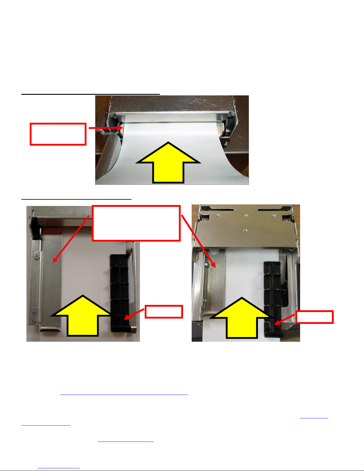
5.1 Ticket Width Adjustment
Ticket Stock
Slider Bar, NOTE: stock
must go under the slider
bar.
Load your stock towards this
side and below this metal plate
Ticket Stock
To adjust the paper path for use with a different ticket width, adjust the slider bar to the fully open position.
Insert your ticket stock into the paper guide. Adjust the slider bar down to the proper ticket width, making sure
the bar is not too tight against the ticket. The ticket should move freely in the paper guide.
Lemur-Z with paper guide Lemur-X
Click here to return to > Table of Contents
16
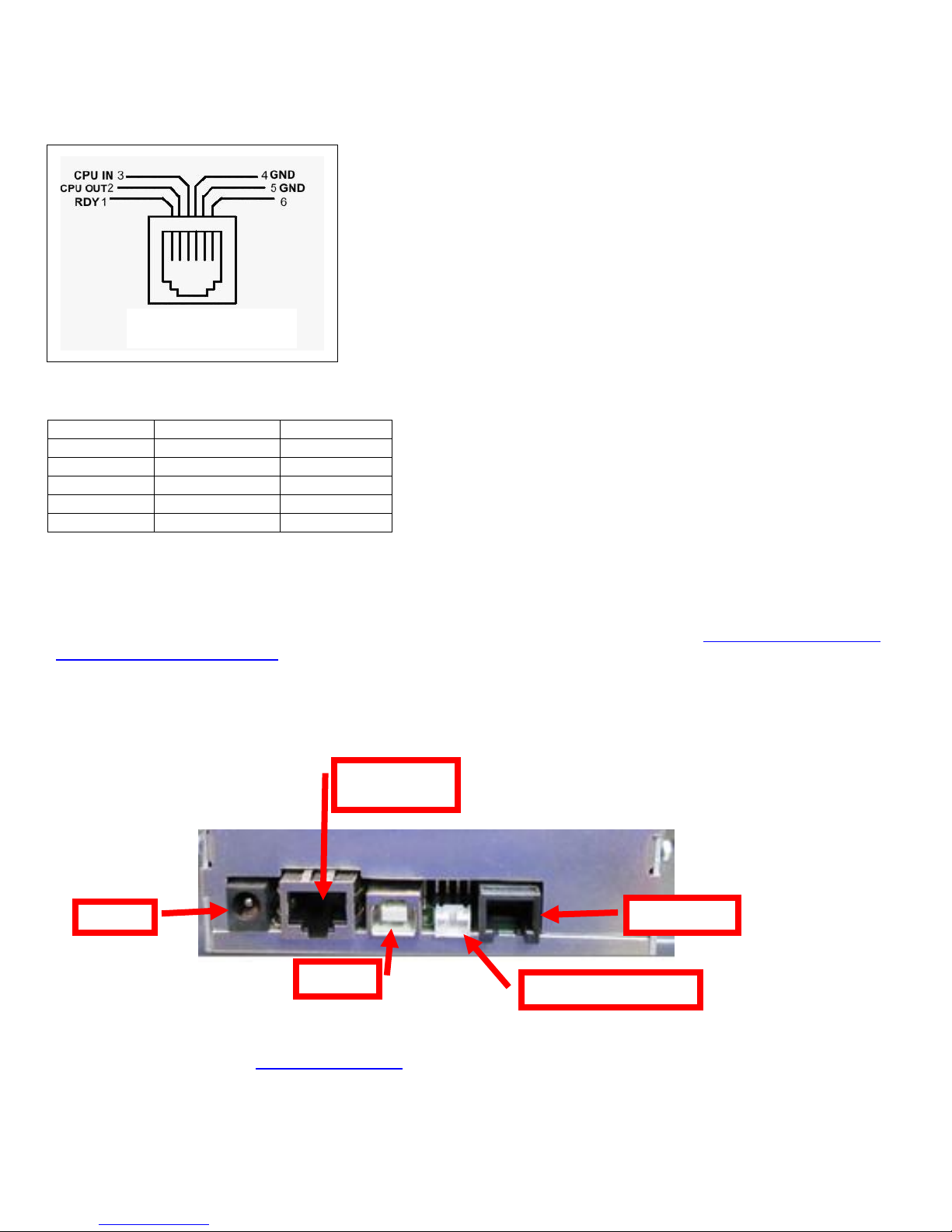
6.0 Standard Interface Pinouts
9 pin host
BOCA RJ12
2
2
Transmit 3 3
Receive 5 4
GND 6 1
RDY 8 6
CTS
+5VDC
RJ12 Connector
USB
RJ12 serial
Ethernet
(Optional)
Low Paper port
RJ12 Serial Connection
TYPICAL DB9 to RJ12 PIN CONNECTIONS
USB USB 2.0 compliant devices.
ETHERNET (Optional) is a standard RJ45 Ethernet cable connection.
Low Paper Port used in conjunction with the roll holder with low paper sensor. See section 4.2.1 Receipt Roll Holder
with Optional Low Paper Sensor.
Click here to return to > Table of Contents
 Loading...