

TLS TLS430FDCEx1 Series, TLS430FDCRx1 Series, TLS430FDCXx1 Series Installation, Operation & Service Parts Manual
1
Part Number: M-430-1
Effective: Nov. 21 , 2013
READ the Manual Thoroughly Before Installing,
Operating, Servicing, or Maintaining the Lift
SAVE this MANUAL and ALL INSTRUCTIONS
Total Automotive Lifting Solutions Inc.
2300 Speers Rd. Oakville, Ontario L6L 2X8
Phone: (905) 847-1198 Fax: (905) 891-1214
www.TLSLifts.com
30,000 lb. (13636 kg) Closed Front 4-Post Lifts
TLS430FDCEx1 (27’ Service Deck) TLS430FDCXx1 (24’ Service Deck)
TLS430FDCRx1 (20’ Service Deck)

2
Your new lift will provide years of dependable service if installed, operated and maintained
properly. Follow all safety, installation, operation, and maintenance
instructions in this manual before installing and operating the lift. In
addition, follow all safety and other information included on and with
the lift before operating the lift. Keep this manual in a secure place
for future reference, training and service part identification.
TABLE of CONTENTS
1. Unloading Procedure and Lift Package Contents page 3
2. Warranty and Safety page 4
3. General Requirements and Lift Specifications page 7
4. Tools Required and Pre Installation Procedures page 8
5. Installation Procedures page 10
6. Operating Instructions and Lift Maintenance page 13
7. Troubleshooting page 18
8. Lift Installation Diagrams and Parts Lists page 20
IMPORTANT : It is the shop owner's responsibility to provide a satisfactory
installation area for the lift. Lift should only be installed on level concrete floors with no more
than 3º of slope and with a minimum of 4 inches (102mm) and 3000 psi (20.7MPa) concrete
that has been aged a minimum of 30 days. Please consult a qualified individual if any doubt
exists concerning proper installation and subsequent safe operation of the lift. Do not install
the lift on asphalt or outdoors. Failure to comply with these minimum standards could result
in personal injury or death.
Prior to installation, it is the shop owner's responsibility to provide constant electrical
power in the correct voltage, phase, etc., and all wiring for electrical hook-up of the lift. The
shop owner must insure that the electrical installation conforms to local building and safety
codes. Where required, the shop owner will provide an electrical isolation switch located in
close proximity to the lift. This switch will have an emergency stop capability and isolate
electrical power from the lift for servicing requirements.
It is the shop owner's responsibility to provide necessary lockout/tagout means for
energy sources per ANSI Z244.1-1982 (R1993), Safety Requirements for the Lockout/Tagout
of Energy Sources, before beginning any lift repairs.
Hydraulic oil cannot be shipped with the lift and will be supplied by either the shop owner or
the installer. ISO 32 hydraulic oil (10W non detergent hydraulic oil) must be used to fill the
reservoir tank before operating the lift.
It is the shop owner's responsibility to train all operators in
lift operation and lift safety.

3
UNLOADING PROCEDURE and LIFT PACKAGE CONTENTS
For your information:
All lift components are packaged together in one module held together by steel frames
Optional accessories (rolling jacks) are packaged separately.
UNPACKING PROCEDURE:
When the lift arrives on site: - If possible have lift unloaded in the installation area and on
two 4"x 4" x 28" Wooden Blocks (required for unpacking)
- Check for freight damage and report immediately to the
trucking company who delivered the lift
- Check for missing parts and report immediately to the factory
1 - 877 - 799 - LIFT (5438) or (905) 847 - 1198
Main Components include:
Columns – 4 pcs
Runway Assemblies – 2 pcs
Crossmembers – 2 pcs (1 front and 1 rear)
Approach Ramps – 2 pcs
Accessory and Hardware Box (see list below)
Optional Accessories: (included only if ordered)
Rolling Air/Hydraulic Jacks - 1 jack per box c/w coiled air line
Accessory Box includes:
Powerpack – 1 pc
Lifting Cables – 4 pcs
Hydraulic Hose – 1 pc
Wheel Stops – 2 pcs
Anchor Bolts – 16 pcs
WL 200 Series Safety Information Label Kit
ALI - “Lifting It Right “ Manual
ALI - “Vehicle Manufacturer's Lifting Point Guide" (CD)
Automotive Lift Safety Tips Hang Card
Automotive Lift, Operation, Inspection and Maintenance Manual
Owner’s Manual
Hardware Box includes: fittings, bolts, washers, nuts, anchor bolts, etc.

4
WARRANTY and SAFETY
Warranty: The four post lift models identified in this manual have the following warranty
from date of purchase:
Structural Components - 1 year Accessory Items - 90 days
Hydraulic and Other Components - 1 year Labor - 1 year
The above items are warranted to be free of defects in material and workmanship to the
original owner of the lift as follows: During the first year (90 days for accessories), those parts
proven after inspection to be defective shall be repaired or replaced at the option of the
manufacturer. This warranty does not extend to defects caused by ordinary wear, misuse,
abuse, improper maintenance, shipping damage or where repairs have been attempted or
made by anyone other than the manufacturer or a manufacturer certified technician. This
warranty is exclusive and in lieu of all other warranties express or implied. In no event shall
the manufacturer be liable for special, incidental or consequential damages for any breach or
delay in performance of the warranty. The manufacturer reserves the right to change
specifications, designs or add improvements to its product line without incurring any
obligation to make such changes to products sold previously.
IMPORTANT SAFETY INSTRUCTIONS
When using your garage equipment, basic safety precautions should always be followed,
including the following:
1. Read all instructions
2. Care must be taken as burns can result from touching hot parts
3. Do not operate equipment with a damaged cord or if equipment has been dropped or
damaged – until it has been examined by a qualified service person
4. Do not let a cord hang over the edge of the table, bench, or counter or come in
contact with hot manifolds or moving fan blades
5. Let equipment cool completely before putting away. Loop cord loosely around
equipment when storing
6. To reduce risk of fire, do not operate equipment in the vicinity of open containers of
flammable liquids (gasoline)
7. Adequate ventilation should be provided when working on operating internal
combustion engines
8. Keep hair, loose clothing, fingers, and all parts of body away from moving parts
9. To reduce the risk of electric shock, do not use on wet surfaces or expose to rain
10. Use only as directed in this manual. Use only manufacturer’s recommended
attachments
11. ALWAYS WEAR SAFETY GLASSES. Everyday eyeglasses only have impact resistant
lenses, they are not safety glasses
12. Basic common sense safety precautions should always be followed when installing,
operating and maintaining the lift as a risk of fire, electric shock, injury or death may
be present.
SAVE THESE INSTRUCTIONS

5
In addition:
1. Read and follow all safety instructions and decals included with the lift. Read and follow
all safety instructions in this manual. Read and follow the ALI "Lifting It Right" manual
(included with the lift). Always use the "Vehicle Lifting Points" reference guide when lifting
a
vehicle. Insure all materials stay up to date »» www.autolift.org/
2. Only trained and authorized personnel should position a vehicle and operate the lift. Do
not allow customers or bystanders to operate the lift or be in the lift area.
3. Inspect the lift daily. Do not operate if potential problems have been identified or lift
malfunctions. Do not operate if lift has damaged or broken components. Never walk or
work under the lift unless all safety locks are completely engaged.
4. Never overload the lift. The rated capacity decal is located on the powerpack column.
The
hydraulic system on this lift is not designed to be a load holding device. Mechanical safety
locks must be engaged before proceeding under the lift for vehicle servicing or lift
maintenance. Never override operating controls. This is unsafe and will void the warranty.
5. Before driving a vehicle onto the lift, insure that both slip plates and turn plates have all
lock mechanisms securely in place. Also insure that the lift and lift area is clear of all
debris
and that all oil and grease has been cleaned from runway surfaces.
6. Before raising or lowering the lift, always totally secure the vehicle with wheel chocks.
7. When using a jack(s) to raise a vehicle, position jack lifting pads to contact vehicle
manufacturers recommended lifting points. Raise jack slowly until all pads contact the
vehicle. Confirm that the vehicle is stable on the jack(s) before raising to desired working
height.
8. Some pickup trucks may require optional truck adapters to clear running boards and other
installed accessories. Special care must be exercised with pick-up trucks to insure safe
lifting. Always use vehicle manufacturers lifting points and insure the contents of the
cargo box will not affect vehicle balance while on the jack(s).
9. Important: Removal or installation of heavier parts can change the vehicle's center of
gravity on the jack(s) resulting in a critical load shift. The vehicle may then be unstable.
Plan ahead for this possibility to insure continued safety and refer to the vehicle
manufacturer’s service manual for recommended procedures.
10. Always keep the lift area free of obstructions and debris. Grease and oil spills should be
cleaned up immediately.
11. Never raise a vehicle on the lift with passengers inside. Before lowering, check the lift
and lift area and remove all obstructions. Before removing vehicle from the lift or lift
area, confirm an unobstructed exit.
12. DO NOT PERFORM ANY MAINTENANCE OR INSTALLATION OF ANY COMPONENTS WITH
OUT FIRST ENSURING THAT ELECTRICAL POWER HAS BEEN DISCONNECTED AT THE
SOURCE OR PANEL AND CANNOT BE RE-ENERGIZED UNTIL ALL MAINTENANCE AND/OR
INSTALLATION PROCEDURES ARE COMPLETED (ANSI 244.1).

6
Safety Instruction and Information Decal Kit (included with the lift)
Review all safety
information daily
with all lift
operators
LIFT SAFETY and LIFT MAINTENANCE
MUST BE PART OF YOUR DAILY ROUTINE
IMPORTANT:
Insure Safety Instruction
Decals and Hang Card are
affixed to the lift
immediately following
installation and before
the lift is used
7
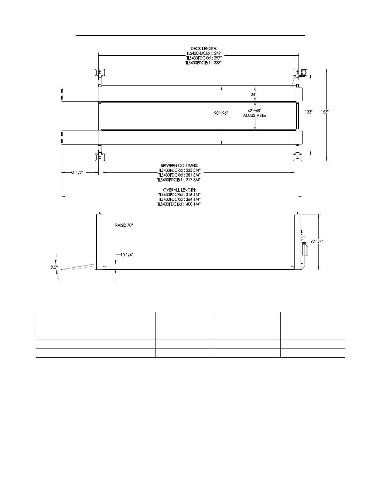
GENERAL REQUIREMENTS and LIFT SPECIFICATIONS
MODEL
TLS430FDCRx1
TLS430FDCXx1
TLS430FDCEx1
Min. Wheelbase @ Rated Capacity
230’’
230’’
230’’
Min. Wheelbase @ 75% Capacity
195’’
195’’
195’’
Min. Wheelbase @ 50% Capacity
165’’
165’’
165’’
Min. Wheelbase @ 25% Capacity
130’’
130’’
130’’
Ongoing design modifications and quality improvements may change specifications listed in this manual without notice
Lift should only be installed on level concrete floors with no more than 3º of slope and
a minimum of 4 inches (102mm) and 3000 psi (20.7MPa) concrete that has been aged a
minimum of 30 days. A qualified person should be consulted to address seismic loads
and other local or state requirements. Do not install the lift on asphalt or outdoors.
A constant supply of 230 volt – 1 phase – 60 Hz – 30 amp electrical power is required
for this lift.
Max. Capacity 30,000 lb. (13,636 kg) - 15,000 lbs. (6,818 kg) each Runway

8
TOOLS REQUIRED and PRE INSTALLATION PROCEDURES
Tools Required:
35ft. Measuring Tape - Chalk Line and Chalk
4"x 4" x 28" Wooden Blocks
Fork Lift - Floor Jacks (2) - or engine crane
Work Stands - 4 (runway set-up and installation)
Metric and SAE Wrenches and Ratchet Sets
Metric and SAE Allen Key Sets
Crow Bar - Hammer - Screwdrivers
2 x 4 ft. Level (laser level also suggested)
Rotary Hammer Drill c/w ¾ inch diameter Masonry Drill Bit
Step Ladder
PRE-INSTALLATION PROCEDURE
Before proceeding with installation, read the installation manual and insure all instructions
are fully understood and all component parts listed on page 3 are accounted for.
Identify bay center line near the front and mark the floor. Also mark center of the bay
entrance. Connect these two points with a chalk line "L1". Refer to diagram on the next
page for minimum clearance from bay entrance door and draw a second chalk line "L3" at
90° to the centerline. Refer to diagram and mark approximate locations of two rear columns.
Refer to the diagram at right for measurements and minimum clearance from front wall or
work bench and draw a third chalk line "L2" at 90° to the centerline. Refer to diagram and
mark the locations of all four columns. These locations will be used to initially position
each column, however, the 4 most critical measurements will be inside column to
inside column measurements confirmed later in the installation process.
Confirm that the column baseplate locations you have marked are a minimum distance of six
(6) inches from any floor seam. Do not install if floor has cracks or deterioration that could
affect lift stability. The shop owner is responsible for confirming there are no obstructions in
the installation area like floor drains, under floor piping or electrical conduit that could be
damaged or prevent safe lift installation and secure lift anchoring. Check ceiling for beams or
heating ducts and walls for protruding structures, etc. (overhead clearance must be 84 inches
plus the height of the tallest vehicle you want to lift). Insure that the lift can be safely installed in
the position you have marked out on the bay floor.

9
DESCRIPTION
TLS430FDCRx1
TLS430FDCXx1
TLS430FDCEx1
A
Baseplate to baseplate
260.5’’
308.5’’
344.5’’
B
Baseplate to baseplate
153’’
153’’
153’’
C
Rear baseplate to door
Min. 60’’
Min. 60’’
Min. 60’’
D
Front baseplate to door
Min. 320.5’’
Min. 368.5’’
Min. 404.5’’
E
Diag. measurement
EQUAL
EQUAL
EQUAL
F
Baseplate to obstacle
Min. 60’’
Min. 60’’
Min. 60’’
G
Baseplate to baseplate
129’’
129’’
129’’
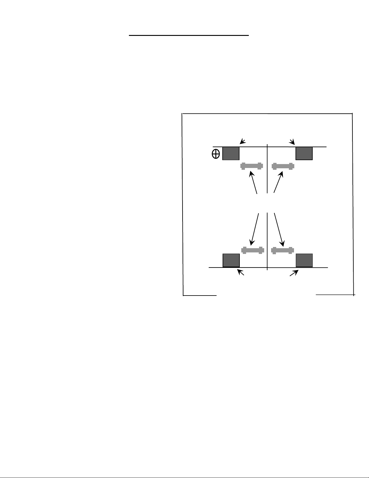
10
Bay Entrance Door
FRONT
Work Stands
for runway
placement
Left Side
(driver side)
Right Side
(passenger side)
Powerpack
Column
column locations
column locations
INSTALLATION PROCEDURE
Insure the lift installation complies with ANSI/ALI/ALIS, Safety Requirements for Installation
and Service of Automotive Lifts.
1. Remove protective wrapping from the lift and clear installation area of packaging
materials. Place two 4"x4"x 24 " wooden blocks under the lift to enable fork lift or other
access and to allow for removal of shipping frames. Unbolt steel shipping frames and
remove from installation area. Take adequate precautions when working with runways,
columns and other components.
2. Work stands are recommended
for safety and ease of runway
and carriage assembly. As an
alternative, use wooden blocks
to raise runways off the floor.
Position work stands (or wooden
blocks) as shown in the diagram
to the right.
3. Identify front crossmember and set it
securely on top of front work stands.
Insure the end with 2 single pulleys is
next to the powerpack (driver side)
column. Unbolt one of the guide blocks
on each end of the front crossmember.
4. Place one front column into each end of
the front crossmember insuring the
guide blocks are centered in the grooves
of the column walls. (To do this, safety
ladder must be pulled out from the tower
and then put back into the crossmember).
5. Slide the unbolted guide blocks you removed in step 3 down from the top of each column
and bolt back in place on the crossmember ends.
6. Carefully lift rear crossmember and set it securely on top of the rear work stands. Insure
the end with 2 double pulleys is on the same side as the powerpack (driver side) column
and in line with the front crossmember single pulley (see diagram #6 - cable routing).
7. Unbolt one of the guide blocks on each end of the rear crossmember.
8. Place one rear column into each end of the rear crossmember insuring the guide blocks
are centered in the grooves of the column walls.
9. Slide the unbolted guide blocks you removed in step #7 down from the top of each
column and bolt back in place on the crossmember ends.
10. Carefully lift the left (driver side) runway and set it securely on top of both front and rear

11
crossmembers. Confirm this runway has the hydraulic cylinder underneath. Also confirm
this runway has the hydraulic hose connection located at the front next to the powerpack
column. Make sure the cylinder bottom hinge is close to rear columns (see diagram #6
for cylinder direction). Insure that both the front and rear of the runway is seated
properly on both crossmembers. If the runway does not seat properly on both
crossmembers, carefully move one or both crossmember and column assemblies slightly
to fit on its crossmember support.
11. Carefully lift the right (passenger side) runway and set it securely on its support on top of
both front and rear crossmembers.
12. Route the lifting cables as shown in diagram #6. Insure that no cable is crossed during
this process. IMPORTANT: Insure all cables are completely contained and properly
seated in each sheave groove. (Install pulleys under the deck after properly laying the
cable.)
13. Secure each of the four cables in the wire rope anchor located at the shaft end of the
hydraulic cylinder. Put cable retainer(diagram #9, item 5) to secure cables.
14. Attached each cable to the proper column top plate using a washer and 3/4’’ nuts
(reference diagram #4).
15. Use a 4 ft. level to insure each column is vertically plumb and at a 90º angle to the
crossmember. Also insure opposite columns for each crossmember are symmetrical in
configuration. Make only minor adjustments to accomplish this.
16. Reconfirm column level and symmetric position relative to crossmember and opposite
column. Starting with the left front (powerpack) column, drill anchor bolt holes and install
anchor bolts (reference diagram #8).
17. Reconfirm column level and symmetric position relative to crossmember and opposite
column for each of the three remaining columns. Drill and install anchor bolts (reference
diagram #8). Shim anchor bolts if necessary.
18. Install runway approach ramps and wheel stops to the runways (diagram #15 and #16).
19. Install powerpack (diagram #5).
20. Route and connect hydraulic hose (diagram #7).
21. Route air line and connect to air solenoid (diagram #5 and diagram #14).
22. Fill powerpack reservoir with ISO grade 32 hydraulic oil (19 liters or 5 U.S. gallons).
23. Confirm electrical wire is sized for a minimum 30 amp circuit and supplying 208/230
volts. Use a separate circuit for each powerpack. Protect each circuit with a time
delay fuse or circuit breaker. For single phase power use a 30 amp fuse. For three
phase power use a 20 amp fuse. All wiring must comply with national and local codes.
NOTE: All electrical wiring should be installed and connected by a certified electrician.
24. Connect powerpack to shop electrical system.

12
25. Connect air solenoid to shop air system (90~120 psi).
26. Press the manual over-ride button on the air solenoid and confirm that all four safety
latches are working properly. Confirm there are no leaks in the air system.
27. Raise the lift 2 ~ 3 ft. while checking for proper direction of rotation on the electric
motor. Confirm there are no leaks in the hydraulic system.
28. Lower the lift (you may first have to raise the lift slightly to disengage the mechanical
safety locks). When lowering, continuously hold down both the air valve and hydraulic
lowering valve.
29. Raise and lower the lift several times to remove any air from the hydraulic system.
30. Raise the lift 3 ft. and confirm that all four safety latches engage and disengage
completely.
31. Refer to diagram at bottom. Commence adjusting the level of both runways by tightening
or loosening the wire rope (cables) using the ¾ " NC Hex Nut at the top of each column.
(reference diagram #4).
33. Lower the lift and allow it sits at same locking position on each safety ladder, adjust bolts
on those ladders to make sure the lift is leveled at each corner.
32. FINAL TEST: Raise the lift to its highest limit and continue to hold the "UP" switch on the
powerpack for about four (4) seconds. This will test the lifting system for maximum load
capacity. Following this test, check for leaks and tighten any loose connections.
33. Use plastic ties and clamps to secure all hydraulic and air lines that droop or hang down
from the lift. Install a hose protector if required. Insure that no hydraulic or air line
comes in contact with any lifting cable.
34. Operate the lift with a vehicle. Raise and lower the lift three times. Confirm all the
operational functions, equalizing cables and safety lock work well.

13
Insure this manual along with all operation, inspection and
maintenance instructions are delivered to the owner, user
and employer.
LIFT OPERATION: Before lifting a vehicle, insure all operators are qualified,
have been trained and are following all safety instructions. Read and follow the
ALI "Lifting It Right" manual included with the lift. Always use the "Vehicle Lifting
Points" reference guide when lifting a vehicle. Insure all materials stay up to date
» » www.autolift.org/ (see example of SAE J2184 standard below)
Insure that every vehicle will be securely positioned on the lift (use wheel chocks). When
using air/hydraulic rolling jacks, always use vehicle manufacturer's recommended lifting
points. Never allow anyone under the lift when raising or lowering. Always insure
mechanical safety locks are completely engaged on all four columns before
proceeding under the lift or a vehicle.
Lift Operation: Controls on the powerpack and powerpack column perform the following
functions:
- “PUSH BUTTON”: Raise the lift to the desired height by pressing the push button on the
power unit
- "AIR LOCK RELEASE BUTTON": retracts or releases safety locks at all four columns. This
button (along with the "DOWN HANDLE") must be pressed and held during the entire
lowering procedure.
- "DOWN HANDLE": on powerpack pump manifold lowers the lift. Note: Before lowering the
lift you should raise it slightly to remove pressure from safety locks allowing them to
disengage completely.

14
PRE-OPERATION CHECK LIST
Trained Lift Operator
All lift operators must be fully trained and qualified to safely and effectively operate the lift
described and covered in this manual.
Absence of All Obstructions
The total work area must be free of any and all obstructions and be generally clean of oil
and debris.
Visual Inspections
Every lift operator must thoroughly inspect the lift noting any problem area. An
inspection of the floor area and anchor bolts must also be completed. Report any
questionable item.
"No Load" Performance Check
All mechanical safety locks are operating properly and consistently
No External Fluid Leaks
No Lift "Bleed Down".
Effortless and Simultaneous Movement
Level Lifting
All Controls Function Properly
Safety Mechanisms all functional
Previous Operator's Report
Verify with previous operator and/or supervisor that there is no problem with the lift. If
problems have been reported, insure all necessary repairs have been completed.
LIFT OPERATION
Lift Operation
Perform pre-operation check list item by item
Ensure lift is completely lowered
Position vehicle on the lift
Caution
Avoid sudden "starts and stops" during loading and unloading of vehicle
To Load a Typical Vehicle
Identify vehicle wheelbase and refer to page 8 to determine the capacity of the lift, the
gross weight of the vehicle must not exceed the capacity shown in the table.
Position vehicle on the lift runways by using the approaching ramp. Make sure the center of
gravity is located evenly between the columns. The individual axle weight should not
exceed 50% of the lift capacity.
Set vehicle parking brake and chock tires.
Make sure vehicle is neither front nor rear heavy.

15
To Raise the Lift
Push up button to raise the lift by about 10’’.
Check for the vehicle movement and weight distribution. Raise to desired height if secure.
Press "DOWN" handle to lower lift on to the mechanical safeties. Make sure all safety locks
sit on the same position of the safety ladders.
DO NOT WORK UNDER A LIFT THAT IS NOT IN THE LOCK POSITION.
To Lower the Lift
Inspect the lifting area to insure all personnel and debris have been cleared away.
Raise the lift slightly and then disengage all safety locks by pulling the safety release
handle.
Press the lowering lever on the power unit to begin lowering. Safety locks must be all
disengaged during the lowering.
Lower lift completely to the floor and carefully drive off the vehicle from the lift runways.

16
MAINTENANCE INSTRUCTIONS
The maintenance is to be performed by factory trained lift service personnel only.
Important: Regularly inspect the hydraulic pressure developed upon the rated capacity,
and make sure the pressure doesn’t exceed the operating pressure (2500 psi).
LIFT MAINTENANCE : The following is a minimum maintenance schedule:
DAILY: - Raise and lower the lift (with no vehicle) at the beginning of each shift to verify the
runways are level, safety locks are engaging, and the lift is operating properly.
- Check all hydraulic fittings and lines for damage and leaks. Check electrical wiring
for damage. Check all moving parts for uneven or excessive wear. Repair or
replace all damaged, worn, or broken components immediately.
- Clean all debris from the base frame area
- Remove oil/grease on runways and rolling jack lift pads.
WEEKLY: - Check hydraulic fluid in reservoir and top up if required.
- Check cables, cable pulleys and lifting cylinder.
MONTHLY: - Check that all anchor bolts are torqued to 75 ft-lbs (102Nm).
- Clean and lubricate moving parts (diagram 18).
WARNING:
FAIL TO LUBRICATE MAY CAUSE PERMENENT DAMAGE TO THE LIFT.
EVERY YEAR: - Have a certified lift technician inspect and certify all aspects of the lift as per
"Automotive Lift Operation, Inspection and Maintenance" (ALOIM)
guidelines.
EVERY TWO YEARS: - Change and replace hydraulic oil in cylinders and powerpack reservoir.
LUBRICATION SPECIFICATIONS: -where grease is required use a multi-purpose lithium grease
- where lubricating oil is required use a SAE 30 oil
- where hydraulic oil is required use ISO 32 hydraulic oil
(10W non detergent)
The following criteria will determine when a lifting cable is no longer acceptable
for service:
12 randomly distributed broken wires in one lay or four broken wires in one strand in one
lay in running ropes
one outer wire broken at the contact point with the core of the rope, which has worked its
way out of the rope structure and protrudes or loops out from the rope structure
wear of one-third the original diameter of outside individual wires

17
kinking, crushing, birdcaging, or any other damage resulting in distortion of the rope
Rope Diameter (inch)
Max. Allowable Reduction (inch)
Less than or equal to 5/16
1/64
Greater than 5/16 less than 1/2
1/32
Greater than 1/2 less than 3/4
3/64
structure
evidence of heat damage from any cause
reduction from nominal diameter greater than those listed in the following table:
If any of the cable is as shown in the following pictures, do not use.
Note: Attention shall be given to end connections. Upon development of two broken
wires adjacent to socket end connections, the rope shall be resocketed or replaced.
Resocketing shall not be attempted if the resulting rope length will be insufficient for
proper operation.

18
Problem
Possible Causes
Solution
Lift Will Not
Raise or Lower
1. Blown fuse or circuit breaker
2. Tripped thermal overload
3. Incorrect voltage to motor
4. Bad wiring connections
5. "UP" switch burned out
6. Motor windings burned out
1. Replace fuse or reset/replace circuit breaker
2. Reset thermal overload
3. Supply correct voltage to motor
4. Repair and insulate all connections
5. Replace switch
6. Replace motor
Lift Will Not
Raise
1. Air in oil or low oil level
2. Lowering Valve leaks
3. Motor runs backward
4. Pump damaged
5. Pump will not prime
6. Relief Valve leaks
7. Voltage to motor incorrect
8. Lift overloaded
1. Check fluid level, oil seal, bleed system
2. Clean valve or replace
3. Check for correct wiring
4. Repair of replace pump
5. Check fluid level and pick-up tube - replace pump
6. Clean Relief Valve (replace if necessary)
7. Supply correct voltage to motor
8. Verify that loaded vehicle weight does not
exceed rated lift capacity
Lift Will Not
Lower
1. Mechanical locks are engaged
2. Obstruction under lift or in glide
block tracks
3. Faulty lowering solenoid valve
1. Raise unit slightly and disengage mechanical locks
2. Carefully remove obstruction - clean glide block
tracks
3. Replace valve
Lift Will Not
Hold Pressure
1. Contamination in system
2. Internal Cylinder leaks
3. Lowering Valve leaks
4. Check Valve leaks
5. External leaks
1. Check oil level - bleed cylinders - remove
contamination - replace oil seal
2. Check fitting, replace cylinder
3. Contaminated fluid, handle binds, clean valves
4. Clean check valve (replace if necessary)
5. Check all fittings and repair leaks
Lift Will Not
Raise A Vehicle
1. Low hydraulic fluid
2. Malfunction of pressure relief
valve
3. Insufficient electrical voltage
4. Lift overload
5. Motor is running backwards
6. Air in hydraulic oil
7. Pump will not prime
8. Pump is damaged
9. Faulty lowering valve
1. Lower lift. Using ISO grade 32 hydraulic oil, fill
the powerpack reservoir to 1" below the top
2. Clean pressure relief valve. if problem continues,
call a service technician
3. Confirm a 208/230 volt power supply to the lift
4. Check that vehicle weight is evenly distributed and
does not exceed rated capacity.
5. Confirm proper motor rotation - rewire if required
6. Check oil seal and bleed hydraulic system
7. Check hydraulic oil level and pick-up tube.
Replace pump if required
8. Repair or replace pump
9. Clean or replace valve
TROUBLESHOOTING GUIDE
The following are suggestions to consider if you have problems with the lift. Please call a
qualified lift technician and/or a qualified electrician for further clarification and information.

19
Problem
Possible Causes
Solutions
Slow Drift Down
1. Mechanical safety locks not
engaged
2. Powerpack lowering valve
contamination
3. Hydraulic system leaks
1. Raise lift to engage all safety locks then lower lift
and confirm all safety locks are engaged
2. Back flush powerpack by opening manual over-
right valve. Engage "up" switch and down lever at
the same time and run approximately 10 seconds
3. Check cylinder and all fittings for any hydraulic oil
leak
Lift Going Up
Out ofLevel
1. Lift installed on un-level floor
2. Cable(s) out of adjustment
1. Reinstall on level surface
2. re-adjust cables - Call service technician if
problem persists
Anchors Will Not
Stay Tight
1. Holes drilled oversize
2. Concrete floor thickness or
holding strength not sufficient
1. Relocate lift using the correct bit to drill holes
2. Break out old concrete and re-pour new
foundation per lift installation instruction
Call factory for technical assistance if lift becomes inoperative in the raised position, and the
maximum operating hydraulic pressure developed upon lifting the rated capacity.
Replace all worn or broken parts and components only with
manufacturer approved/supplied parts and components
Replacement parts may be purchased from your local lift supplier or
the manufacturer at: 1-877-799-LIFT(5438) or (905) 847 – 1198

20
for installation & service part reference
SAVE this MANUAL and ALL INSTRUCTIONS
Total Automotive Lifting Solutions Inc.
2300 Speers Rd. Oakville, Ontario L6L 2X8
Phone: (905) 847-1198 Fax: (905) 891-1214
www.TLSLifts.com
Part Number: M-430-1
Effective: Nov. 20 , 2013
30,000 lb. (13636 kg) Closed Front 4-Post Lifts
TLS430FDCEx1 (27’ Service Deck) TLS430FDCXx1 (24’ Service Deck)
TLS430FDCRx1 (20’ Service Deck)

21
LIFT ILLUSTRATIONS and PARTS LISTS
The diagrams listed below, along with related parts lists, will assist you when installing and
servicing this lift. Please ensure these lift diagrams and parts lists are kept in a secure place
for quick reference.
Diagram #1 - Lift Assembly…....................................................................page 22
Diagram #2 - Front Crossmember………………………………………………….……….page 23
Diagram #3 - Rear Crossmember…………………………………………………….……..page 25
Diagram #4 - Tower Assembly……………………………………………………….….……page 27
Diagram #5 - Power Unit and Air Kit Mounting………………………………….……..page 28
Diagram #6 - Lifting Cable Routing………………………………………………….……..page 29
Diagram #7 - Hydraulic Line Assembly……………………………………………….……page 31
Diagram #8 - Anchor Bolt Installation……………………………………………………..page 32
Diagram #9 - Driverside Runway Assembly………………………………………………page 33
Diagram #10 - Cylinder Guide Assembly…………………………………………………….page 35
Diagram #11 - Safety Lock Assembly (A & B)…………………………………………….page 36
Diagram #12 - Cable Lock Assembly A………………………………………………………page 37
Diagram #13 - Cable Lock Assembly B………………………………………………………page 38
Diagram #14 - Pneumatic Controls…………………………………………………………...page 39
Diagram #15 - Wheel Stop Assembly…………………………………………………………page 40
Diagram #16 - Ramp Assembly…………………………………………………………………page 40
Diagram #17 - Power Unit Wiring Diagram…………………………………………………page 41
Diagram #18 - Lubrication Locations…………………………………………………………page 42
Diagram #19 - Safety Instructions…………………………………………………………….page 43

22
Diagram #1: Lift Assembly
ITEM NO.
PART NUMBER
DESCRIPTION
QTY.
1
44300001
TOWER ASSEMBLY
4
2
44300020
27’ DECK ASSEMBLY (DRIVER SIDE)
1
44300030
24’ DECK ASSEMBLY (DRIVER SIDE)
44300040
20’ DECK ASSEMBLY (DRIVER SIDE)
3
24300036
27’ DECK WELDMENT (PASSENGER SIDE)
1
24300026
24’ DECK WELDMENT (PASSENGER SIDE)
24300046
20’ DECK WELDMENT (PASSENGER SIDE)
4
44300009
APPROCHING RAMP
2
5
44180012
WHEELSTOP ASSEMBLY
2 6 44300005
CROSSBEAM ASSEMBLY (FRONT)
1 7 44300004
CROSSBEAM ASSEMBLY (REAR)
1

23
Diagram #2: Front Crossmember

24
ITEM NO.
PART NUMBER
DESCRIPTION
QTY.
1
24300005
FRONT BEAM WELD.
1 2 44300006
PULLEY ASSEMBLY
10 3 14300051
SAFETY PIN
4 4 14180049
SLIDER BLOCK
8 5 34180000
BIMBA CYLINDER
4 6 14180031
AIR CYLINDER TAPPET
4 7 24300013
CROSSBEAM PULLEY SHAFT WELD.
4 8 44300007
SAFETY LOCK ASSEMBLY A
2
9
44300007
SAFETY LOCK ASSEMBLY B
2
10
44300008
CABLE LOCK ASSEMBLY A
2
11
44300008
CABLE LOCK ASSEMBLY B
2
12
24300015
FRONT & REAR PULLEY SHAFET WELD.
2
13
14300037
SHEAVE COVER
4
14
24300017
PULLEY SPACER WELD.
8
15
31140013
GREASE FITTING
6
16
14180078
SAFETY LOCK SPRING
4
17
14180089
CABLE LOCK SPRING
4
18
3C000039
5/16’’-18X3’’ HEX BOLT
16
19
3C000185
1 1/2’’ FLAT WASHER
4
20
3C000053
1’’ RETAINING RING
8
21
3C000182
#10 SELF TAPPING SCREW
12
22
3C000000
5/16’’ SPRING LOCK WASHER
33
23
3C000023
5/16’’ FLAT WASHER
20
24
3C000001
5/16’’-18X3/4’’ HEX BOLT
7
25
14300202
PULLEY COVER
2

25
Diagram #3: Rear Crossmember

26
ITEM NO.
PART NUMBER
DESCRIPTION
QTY.
1
24300006
REAR BEAM WELD.
1 2 44300006
PULLEY ASSEMBLY
10 3 24300015
FRONT & REAR PULLEY SHAFT WELD.
2 4 24300013
CROSSBEAM PULLEY SHAFT WELD.
4 5 14180049
SLIDER BLOCK
8 6 14300051
SAFETY PIN
4 7 44300007
SAFETY LOCK ASSEMBLY B
2 8 44300007
SAFETY LOCK ASSEMBLY A
2
9
44300008
CABLE LOCK ASSEMBLY A
2
10
44300008
CABLE LOCK ASSEMBLY B
2
11
14300037
SHEAVE COVER
4
12
34180000
AIR CYLINDER
4
13
14180031
AIR CYLINDER TAPPET
4
14
3C000000
5/16 SPRING LOCK WASHER
33
15
3C000185
1 1/2'' FLAT WASHER
4
16
31140013
GREASE FITTING 1/4-20 UNC
6
17
14300202
PULLEY COVER
2
18
3C000182
#10 SELF TAPPING SCREW
12
19
24300017
PULLEY SPACER WELD.
8
20
3C000023
5/16 REGULAR WASHER
20
21
3C000039
5/16''-18 X3'' HEX BOLT
16
22
3C000001
5/16''-18 X 3/4'' HEX BOLT
7
23
3C000053
1'' RETAINING RING
8
24
14180078
SAFETY LOCK SPRING
4
25
14180089
CABLE LOCK SPRING
4

27
Diagram #4: Tower Assembly
ITEM NO.
PART NUMBER
DESCRIPTION
QTY.
1
24300001
TOWER WELDMENT
4 2 24300002
SAFETY LADDER
4 3 3C000152
3/8’’ WASHER
4 4 3C000141
3/8’’X1 1/2’’ BOLT
4
5
3C000035
3/4’’ WIDE WASHER
4
6
3C000046
7/8’’ WIDE WASHER
4 7 3C000036
3/4’’ HEX NUT
8 8 3C000047
7/8’’ HEX NUT
8

28
Diagram #5: Power Unit and Air Kit Mounting
ITEM NO.
PART NUMBER
DESCRIPTION
QTY.
1
34300200
POWER UNIT
1 2 44180011
PNEUMATIC CONTROLS
1 3 3C000144
5/16’’ BOLT
4
4
3C000000
5/16’’ SPRING LOCK WASHER
33
5
3C000143
5/16'' FLAT WASHER
4 6 3C000145
5/16'' HEX NUT
4 7 3C000051
1/4’’ HEX BOLT
2 8 3C000044
1/4 SPRING LOCK WASHER
20 9 3C000147
1/4'' HEX NUT
2

29
Diagram #6: Lifting Cable Routing

30
Extra Long Model (TLS430FDCEx1, 27’ Deck)
ITEM NO.
PART NUMBER
Description
OAL
QTY.
1
34300100
DRIVER FRONT CABLE
299.5’’
1
2
34300101
PASSENGER FRONT CABLE
368.5’’
1
3
34300102
DRIVER REAR CABLE
420’’
1
4
34300103
PASSENGER REAR CABLE
489’’
1
ITEM NO.
PART NUMBER
Description
OAL
QTY.
1
34300104
DRIVER FRONT CABLE
263.5’’
1
2
34300105
PASSENGER FRONT CABLE
332.5’’
1
3
34300102
DRIVER REAR CABLE
420’’
1
4
34300103
PASSENGER REAR CABLE
489’’
1
ITEM NO.
PART NUMBER
Description
OAL
QTY.
1
34300106
DRIVER FRONT CABLE
215.5’’
1
2
34300107
PASSENGER FRONT CABLE
284.5’’
1
3
34300102
DRIVER REAR CABLE
420’’
1
4
34300103
PASSENGER REAR CABLE
489’’
1
Extended Model (TLS430FDCXx1, 24’ Deck)
Standard Model (TLS430FDCRx1, 20’ Deck)

31
Diagram #7: Hydraulic Line Assembly
ITEM NO.
PART NUMBER
Description
QTY.
1
34300002
HYDRAULIC HOSE (3/8’’ JIC PORT)
1
2
3H000002
ELBOW FITTING, 1/4’’ NPT X 3/8’’ NPT
1
3
3H000003
FLOW CONTROL FITTING, 3/8’’ NPT PORT
1
4
3H000004
MALE 3/8’’ NPT X 3/8’’ JIC
1
5
3H000001
MALE #6 SAE X FEMALE 3/8’’ JIC FITTING
1

32
Diagram #8: Anchor Bolt Installation

33
Diagram #9: Driver Side Runway Assembly

34
ITEM NO.
PART NUMBER
DESCRIPTION
QTY.
1
24300035
27’ DECK WELD. CYLINDER SIDE
1
24300025
24’ DECK WELD. CYLINDER SIDE
24300045
20’ DECK WELD. CYLINDER SIDE
2
44300006
PULLEY ASSEMBLY
10 3 44300010
CYLINDER ASSY
1 4 14300080
CABLE HOLDER
1
5
14300081
CABLE RETAINER
1
6
34300020
1 1/2'' - 12 UNF JAM NUT
1 7 14300082
CYLINDER PIN
1
8
24300016
Middle Deck Pulley Shaft Weld.
1
9
44300011
CYLINDER GUIDE
1
10
3C000000
5/16 SPRING LOCK WASHER
33
11
3C000187
5/16''-18 X 1.5'' HEX BOLT
2
12
3C000001
5/16''-18 X 3/4'' HEX BOLT
7
13
3C000190
1 3/4'' RETAINING RING
2
14
31140013
GREASE FITTING 1/4-20 UNC
7

35
Diagram #10: Cylinder Guide Assembly
ITEM NO.
PART NUMBER
DESCRIPTION
QTY.
1
14180069
TRUNNION GUIDING PLATE
1
2
14180076
TRUNNION GUIDE BLOCK
4
3
3C000015
SOCKET COUNTERSUNK SCREW
8

36
Diagram #11: Safety Lock Assembly (A & B)
ITEM NO.
PART NUMBER
DESCRIPTION
QTY.
1
24300008-A
SAFETY LOCK WELD. A
2 2 24300014
SAFETY LOCK LEVER WELD.
4 3 3C000043
1/4’’ FLAT WASHER
16 4 3C000044
1/4’’ SPRING LOCK WASHER
20 5 3C000181
1/4-20X3/4’’ HEX BOLT
16
ITEM NO.
PART NUMBER
DESCRIPTION
QTY.
1
24300008-B
SAFETY LOCK WED. B
2 2 24300014
SAFETY LOCK LEVER WELD.
4
3
3C000043
1/4’’ FLAT WASHER
16 4 3C000044
1/4’’ SPRING LOCK WASHER
20 5 3C000181
1/4-20X3/4’’ HEX BOLT
16
Driver Front & Passenger Rear (A)
Driver Rear & Passenger Front (B)

37
Diagram #12: Cable Lock Assembly A
ITEM NO.
PART NUMBER
DESCRIPTION
QTY.
1
24300009-A
CABLE LOCK WELD. A
2 2 14300057
CABLE LOCK LEVER PLATE
4 3 14180056
BACK-UP LATCH ROLLER
4 4 3C000181
1/4-20 X 3/4 HEX BOLT
16 5 3C000187
5/16''-18 X 1.5'' HEX BOLT
8 6 3C000044
1/4 SPRING LOCK WASHER
20 7 3C000043
1/4 REGULAR WASHER
16 8 3C000023
5/16 REGULAR WASHER
20
Driver Front & Passenger Rear (A)

38
Diagram #13: Cable Lock Assembly B
ITEM NO.
PART NUMBER
DESCRIPTION
QTY.
1
24300009-B
CABLE LOCK WELD. B
2 2 14300057
CABLE LOCK LEVER PLATE
4 3 14180056
BACK-UP LATCH ROLLER
4 4 3C000181
1/4-20 X 3/4 HEX BOLT
16 5 3C000187
5/16''-18 X 1.5'' HEX BOLT
8 6 3C000044
1/4 SPRING LOCK WASHER
20 7 3C000043
1/4 REGULAR WASHER
16 8 3C000023
5/16 REGULAR WASHER
20
Driver REAR & Passenger FRONT (B)

39
Diagram #14: Pneumatic Controls
ITEM NO.
PART NO.
DESCRIPTION
QTY.
1
24180013
PNUEMATIC CONTROLS WELDMENT
1 2 34180013
FILTER
1
3
34180012
LUBRICATER
1
4
34180011
VALVE
1 5 34180010
REGULATOR
1
6
34180015
FITTING
2
7
34180016
FITTING
2
8
34180017
AIR INTAKE FITTING
1 9 31140119
ELBOW 5/32’’ POLY – 1/8’’ NPT
1
10
31141063
TEE FITTING
3
11
31140120
POLYTUBE 5/32" DIA. BLUE
12
34180000
AIR CYLINDER
4
13
31140122
STRAIGHT 5/32" POLY - 1/8" NPT
4
14
31141062
POLY FITTING 3/8" x 1/4" NPT STRAIGHT
3
15
31141056
POLYTUBE 3/8" DIA. BLUE
16
31141061
BRASS FORGED STEEL TEE
1
17
31141060
TERMINAL BOLT (STEEL)
2
18
31140023
Poly Elbow swivel 3/8" x 1/4" NPT
1

40
Diagram #15: Wheel Stop Assembly
ITEM NO.
PART NUMBER
DESCRIPTION
QTY.
1
24180014
WHEELSTOP WELDMENT
2 2 11140128
PIVOTING PIN
2
3
3C000030
5/8 NARROW WASHER
4 4 3C000028
5/8’’ RETAINING RING
4
ITEM NO.
PART NUMBER
DESCRIPTION
QTY.
1
24300012
RAMP WELD.
2
2
14300119
RAMP HINGE SHAFT
2
3
3C000029
3/4’’ RETAINING RING
4 4 34300300
3/4’’ EXTRA NARROW WASHER
4
Diagram #16: Ramp Assembly

41
Diagram #17: Power Unit Wiring Diagram

42
Diagram #18: Lubrication Locations

43
Diagram #19: Safety Instructions
 Loading...