

Page 1
User Manual
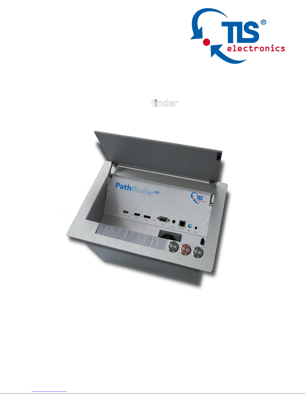
875800 Path
4.0
MF
Page 2
875800 User manual
TLS electronics GmbH Contact: info@tls-electronics.de
Thank you for purchasing this product. For optimum performance and safety, please
read these instructions carefully before connecting, operating or adjusting this product.
Please keep this manual for future reference.
SURGE PROTECTION DEVICE RECOMMENDED
This product contains sensitive electrical components that may be damaged by electrical
spikes, surges, electric shock, lightning strikes, etc. Use of surge protection systems is
highly recommended in order to protect and extend the life of your equipment.
Important Safety Instructions
.
Page 3

875800 User manual
TLS electronics GmbH Contact: info@tls-electronics.de 1
Table of Contents
Introduction ................................................................ 2
Features ..................................................................... 3
Specifications ............................................................. 4
Panel Layout .............................................................. 7
Front Panel .......................................................... 7
Rear Panel .......................................................... 8
Quick Start ................................................................. 9
Connections and Installation .................................... 12
Web Control ............................................................. 13
WEB GUI Introduction .............................................. 13
Status ................................................................ 13
Configuration ............................................................ 14
Device ............................................................... 14
Video ................................................................. 19
Control ............................................................... 20
Advanced ................................................................. 22
Welcome Menu .................................................. 23
System ............................................................... 23
Device List Window .................................................. 27
EDID Management ............................................ 28
Package Contents .................................................... 29
Maintenance ............................................................ 30
Limitations of Warranty ...................................... 30
RMA Policy ........................................................ 32
Page 4

875800 User manual
TLS electronics GmbH Contact: info@tls-electronics.de 2
Introduction
Pathfinder 4.0 MF is a 100m 4K Daisy-chain Presenter with HDBaseT in and
HDBaseT out, and utilizes HDBaseT technology as daisy-chain medium to
cascade multiple A/V sources, displays or any devices with HDBaseT
connection together in a chain to set up an A/V distribution system. The system
is cascadable up to 64 devices.
Pathfinder 4.0 supports three video inputs including HDMI, Display Port and
VGA plus 3.5mm audio in, with HDBaseT input and HDBaseT output for
cascading. A local HDMI out with audio de-embedder is provided in the rear side
to connect local monitor or zone displays. It has a 2-Port Ethernet Switch built-in,
so that Ethernet could pass through over HDBaseT for LAN control, or to feed
LAN access to sources or displays. RS232 port is used to pass through RS232
commands or control display device. USB charger is also provided to charge
mobile devices. It offers Select button and Contact Closure to switch sources,
and rotary switch for EDID management.
Pathfinder 4.0 offers a future-ready Ultra HD A/V switching and distribution
solution, and cutting-edge HDMI 2.0 and HDCP 2.2 compatibility. With
user-friendly WEB GUI and Telnet API to configure advanced functionality
including CEC controller, RS232 controller and Daisy-chain Grouping, it is
perfectly suitable for collaboration or presentation in conference and education
application.
Pathfinder also offers a power socket for 230V/10A to work with a laptop.
Special regional power sockets are available.
Page 5

875800 User manual
TLS electronics GmbH Contact: info@tls-electronics.de 3
Features
HDMI, DisplayPort and VGA plus stereo switching inputs, local HDMI
bypass out with audio de-embedder
HDBaseT input and output to cascade multiple A/V sources and displays
Cascadable up to 64 devices
HDMI 2.0 and input supports HDCP 2.2
Supports 4K@60Hz 4:2:0 8-bit up to 70m over Cat5e/Cat6, or up to 100m
over Cat6a/Cat7
Built in CEC controller and RS232 controller for smart control
Automatic CEC and RS232 command to Power ON/Standby Display, by
detecting input signal status
Daisy-chain Grouping mode offered to match flexible application
LAN control with user-friendly WEB GUI and Telnet API
Select Button and Contact Closure for source switching
Built in 2-Port Ethernet Switch for LAN control or LAN access
Built in USB Charger up to 5V/1.5A to charge mobile devices
Independent rotary switch for EDID management
Advanced signal re-clocking and cable equalization for multiple daisy-chains
Page 6
875800 User manual
TLS electronics GmbH Contact: info@tls-electronics.de 4
Specifications
Video
Input
1 x HDMI IN, 1 x DisplayPort IN,
1 x VGA IN, 1 x HDBaseT IN
Input Signal Type
HDMI: HDMI 2.0 w/HDCP 2.2,
DP: DP 1.2 w/HDCP2.2
Input Resolution
Support
HDMI:
4096 x 2160@24/25/30/50/60Hz,
3840 x 2160@24/25/30/50/60Hz,
1080p@24/25/30/50/60Hz,
1080i@50/60Hz, 720p@50/60Hz,
1920 x 1200@60Hz,
1680 x 1050@60Hz,
1600 x1200@60Hz, 1600 x 900@60Hz,
1440 x 900@60Hz, 1400 x 1050@60Hz,
1366 x 768@60Hz, 1360 x 768@60Hz,
1280 x 1024@60H, 1280 x 960@60Hz,
1280 x 800@60Hz, 1280 x 768@60Hz,
1024 x 768@60Hz, 800 x 600@60Hz
DisplayPort:
800x600@60 Hz, 1024x768@60Hz ,
1280x768@60Hz, 1280x800@60Hz,
1280x960@60Hz, 1280x1024@60Hz,
1360x768@60Hz, 1366x768@60Hz,
1440 x900@60Hz, 1600 x900@60Hz,
1600 x1200@60Hz,
1680 x1050@60Hz,
1920 x1080@60Hz,
1920 x1200@60Hz,
1280x720P@50Hz, 1280x720P@60Hz,
1920x1080P@50Hz,
3840x2160@50Hz, 3840x2160@60Hz,
4096x2160@50Hz, 4096x2160@60Hz.
VGA:
800x600@60 Hz, 1024x768@60Hz ,
1280x768@60Hz, 1280x800@60Hz,
Page 7
875800 User manual
TLS electronics GmbH Contact: info@tls-electronics.de 5
1280x960@60Hz, 1280x1024@60Hz,
1360x768@60Hz, 1366x768@60Hz,
1440 x900@60Hz, 1600 x900@60Hz,
1600 x1200@60Hz,
1680 x1050@60Hz,
1920 x1080@60Hz,
1920 x1200@60Hz,
1280x720P@50Hz, 1280x720P@60Hz,
1920x1080P@50Hz,
Output
1 x HDMI OUT, 1x HDBaseT OUT
Output Signal Type
HDMI 2.0 with 4k, HDBaseT
Output Resolution
Support
HDMI:
4096 x 2160@24/25/30/50/60Hz,
3840 x 2160@24/25/30/50/60Hz,
1080p@24/25/30/50/60Hz,
1080i@50/60Hz, 720p@50/60Hz,
1920 x 1200@60Hz,
1680 x 1050@60Hz,
1600 x 1200@60Hz,
1600 x 900@60Hz, 1440 x 900@60Hz,
1400 x 1050@60Hz, 1366 x 768@60Hz,
1360 x 768@60Hz,
1280 x 1024@60H, 1280 x 960@60Hz,
1280 x 800@60Hz, 1280 x 768@60Hz,
1024 x 768@60Hz, 800 x 600@60Hz
DisplayPort:
800x600@60 Hz, 1024x768@60Hz ,
1280x768@60Hz, 1280x800@60Hz,
1280x960@60Hz, 1280x1024@60Hz,
1360x768@60Hz, 1366x768@60Hz,
1440 x900@60Hz, 1600 x900@60Hz,
1600 x1200@60Hz,
1680 x1050@60Hz,
1920 x1080@60Hz,
1920 x1200@60Hz,
1280x720P@50Hz, 1280x720P@60Hz,
1920x1080P@50Hz, 1920x1080P@60Hz,
3840x2160@50Hz, 3840x2160@60Hz,
4096x2160@50Hz, 4096x2160@60Hz.
VGA:
800x600@60 Hz, 1024x768@60Hz ,
1280x768@60Hz, 1280x800@60Hz,
1280x960@60Hz, 1280x1024@60Hz,
1360x768@60Hz, 1366x768@60Hz,
Page 8
875800 User manual
TLS electronics GmbH Contact: info@tls-electronics.de 6
1440 x900@60Hz, 1600 x900@60Hz,
1600 x1200@60Hz,
1680 x1050@60Hz,
1920 x1080@60Hz,
1920 x1200@60Hz,
1280x720P@50Hz, 1280x720P@60Hz,
1920x1080P@50Hz
Note:
HDBaseT out: HDMI 2.0 with 4k@60Hz
(Chroma sub-sampling 4:2:0 8-bit only)
Video Impedance
100 Ω
Input Video Level
0.5-1.2 V p-p
Input DDC Level
5 volts p-p (TTL)
Maximum Pixel Clock
300MHz
Audio
Input
1 x Audio in for VGA, DP/HDMI/HDBT
embedding audio
Input Connector Type
3.5mm jack
Output
HDMI audio de-embedded, Stereo
Control
Control Method
Select Button, Contact Closure, Telnet,
Web GUI
General
Operating
Temperature
0°C to 45°C (32°F to 113°F)
Storage Temperature
-20°C to 70°C (-4°F to 158°F)
Humidity
10% to 90%, non-condensing
ESD Protection
Human-body Model:
±8kV(Air-gap discharge)/
±4kV(Contact discharge)
Power Supply
DC 12V 3A
Power Consumption
20.52W (Maximum)
Device Dimension
(W x H x D)
223mm x 27mm x 124.2mm /
8.78’’ x 1.06’’ x 4.89’’
Product Weight
0.8kg
Certification
CE, FCC
Page 9
875800 User manual
TLS electronics GmbH Contact: info@tls-electronics.de 7
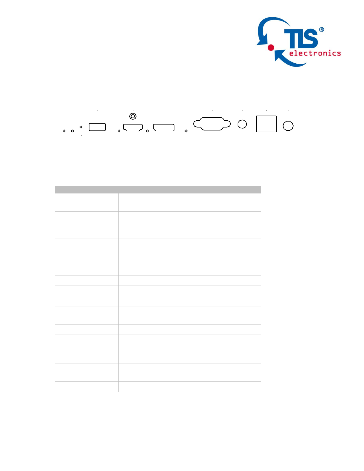
Panel Layout
Front Panel
1 2 3 4 5 6 7 8 9 10 11 12 13 14
No.
Name
Description
1
Locate LED
Located a device in the chain, LED flashes
2 times when click “LocateME” on WEB
2
Power LED
Indicate power status
3
RESET
Press and hold this button for at least five
seconds to reset the Pathfinder
4
USB
CHARGER
Charge USB device
5
HDMI IN
LED
This LED is on if HDMI IN is selected as
input
6
HDMI IN
Connects to HDMI source device
7
DP IN LED
This LED is on if DP IN is selected as input
8
DP IN
Connects to DisplayPort source device
9
VGA IN LED
This LED is on if VGA IN is selected as
input
10
VGA IN
Connects to VGA source device
11
AUDIO IN
VGA analog stereo audio input
12
ETHERNET
Connects to a LAN device such as Laptop
for LAN access or WEB control
13
EDID
Rotary switch is provided to offer EDID
management.
14
Config
Hidden config button
HDMI
AUDIOOn
Reset
DP VGA
ETHERNET
EDID
USB Charger 1,5A
Page 10
875800 User manual
TLS electronics GmbH Contact: info@tls-electronics.de 8
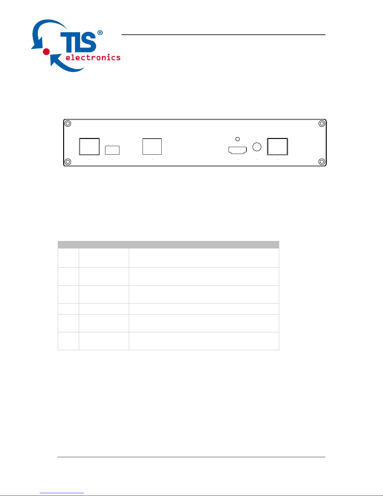
Rear Panel
1 2 3 4 5 6
No.
Name
Description
1
HDBT IN
Connects to HDBT output port of any
HDBT device or the other PathFinder 4.0.
2
RS232
Connects to a controllable device such as
projector as RS232 pass-through
3
Ethernet
Connects to a LAN device such as
IP-based touch panel for LAN control
4
HDMI OUT
Connects to a HDMI display device
5
AUDIO OUT
Connects to audio system such as an
amplifier
6
HDBT OUT
Connects to HDBT input port of any HDBT
device or the other Pathfinder.
TX
HDMI OUT AUDIO INRS232HDBT IN ETHERNET HDBT OUT
RX
T
Page 11

875800 User manual
TLS electronics GmbH Contact: info@tls-electronics.de 9
Quick Start
Pathfinder 4.0 MF could be used flexibly as either transmitter or receiver to
support a couple of different installations and applications, because of a local
HDMI Out port built in.
Application 1: Chain-type Connection
In Application 1, Device 1 and Device 2 are used as transmitter to connect
source, while Device M and Device Z are dedicated receivers to connect
multiple displays.
Application 2: Chain-type Connection with Local Monitor
Page 12

875800 User manual
TLS electronics GmbH Contact: info@tls-electronics.de 10
In Application 2, each Pathfinder in the chain has its local HDMI Out connected
with local monitor, so as to show forward or local source once it’s selected in the
chain. Please note only backward devices could display forward sources, while
forward devices can not have their local monitor to show backward sources.
Application 3: Ring-type Connection
In Application 3, the last Device Z has its HDBT OUT connecting to HDBT IN of
the first Device 1. As a result, each source selected could be displayed by any
monitor in the chain, and fix the issue in chain-type connection that backward
sources can not be displayed in forward monitors.
Page 13

875800 User manual
TLS electronics GmbH Contact: info@tls-electronics.de 11
Application 4: Grouping Mode
In Application 4, Device 1 and Device 2 work in Group 1, while Device M and
Device Z work in separate Group Z. Devices in different groups can not select or
display sources from other groups. Grouping mode is simply activated by Telnet
API or clicking the Daisy-chain Grouping option on the WEB GUI of device, then
the video will stop to be outputted to backward devices.
For example, set Device 2 in grouping mode to make Device 1 and Device 2
work as Group 1, then Device 3 and all backward devices are in the other group;
set Device 2 and Device 4 in grouping mode to make Device 1 and Device 2 in a
group, Device 3 and Device 4 work in a group, Device 5 and backward devices
in the other group (More details please check Page 16.) Both Chain-type and
Ring-type connection could support grouping mode.
Before set up, please take care of below steps:
1. Connect a PC to each device by Ethernet port, log in their WEB GUI to set
static IP address and alias name for every device. (Please check Page 13 to
learn how to log in WEB GUI.)
2. Connect all devices by HDBaseT ports through Cat cable, make a Chain-type
connection firstly and feed LAN access to Ethernet port of any device. Do not
make Ring-type connection directly with LAN access, otherwise there will
be LAN conflicts and LAN control disabled.
3. Log in WEB GUI of the first device in the chain, input total quantity of devices
cascaded within Daisy-chain Sequence and then click Start Sequence.
Page 14
875800 User manual
TLS electronics GmbH Contact: info@tls-electronics.de 12
(More details please check Page 16 Daisy-Chain Sequence).
4. Connect the HDBT OUT of the last device to the HDBT IN of the first device,
log in WEB GUI of the first device to click Start Sequence again, then Ring-type
connection is set up correctly.
Any Pathfinder reset, removed, replaced or newly added in the chain,
please follow above instruction to configure them again.
Connections and Installation
1. Connect the HDBT OUT port of Pathfinder 1 to the HDBT IN port of
Pathfinder 2, connect the HDBT OUT port of Pathfinder 2 to the HDBT IN
port of Pathfinder 3, and follow to daisy-chain multiple Pathfinder through
HDBT ports by Cat cable.
2. Using quality HDMI/DP/VGA cables to connect different sources (such as
Laptop, PC, Blu-ray, satellite/cable TV, etc.) to HDMI IN/DP IN/VGA IN port
of Pathfinder.
3. Using quality HDMI cables to connect the HDMI display device (such as
Projector, Monitor or TV) to the HDMI OUT of Pathfinder.
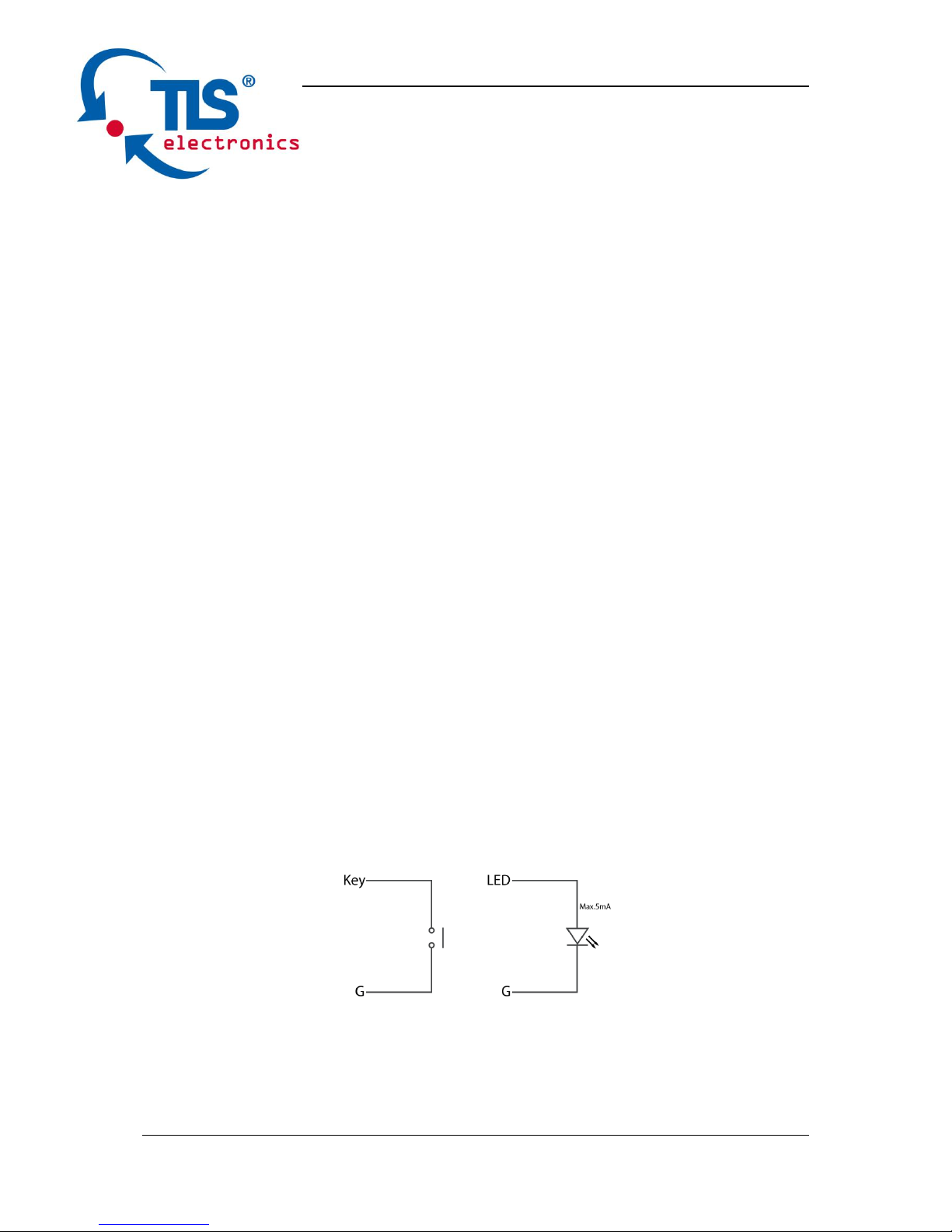
4. Connect a controller such as IP-based touch panel to an Ethernet port of
Pathfinder, or Contact Closure-based keypad to the Select/KEY/LED ports
to control. Circuit diagram of Contact Closure ports including SELECT, KEY
and LED (2,5 - 3,3V – 5 - 8 mA) without any resistors as shown:
5. Power on all devices. Use the Select Button, Contact Closure, WEB GUI or
Telnet API command to operate the Pathfinder.
Note: Quality CAT cables are highly recommended, such as Cat6, AWG 24/1 or
better, S/FTP cable.
Page 15
875800 User manual
TLS electronics GmbH Contact: info@tls-electronics.de 13
Web Control
PathFinder 4.0 offers a Web GUI for product configuration.
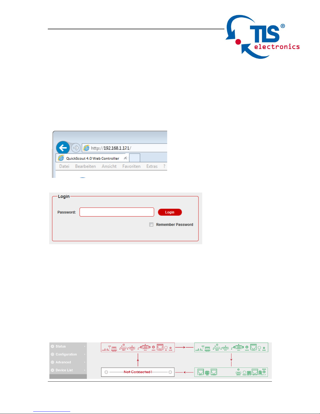
Access the WEB GUI
Step 1. Connect PathFinder 4.0 to a computer using a Cat cable. The default IP
address of the PathFinder 4.0 is 192.168.1.121, make sure the computer's IP
address is 192.168.1.X (such as 192.168.1.100).
Step 2. Type the IP address into a web browser (as seen below).
A login screen will appear:
The default password is admin.
WEB GUI Introduction
The WEB GUI contains three sub-menu: Status, Configuration and Advanced.
Status
This sub-menu displays the current status of PathFinder 4.0.
Page 16

875800 User manual
TLS electronics GmbH Contact: info@tls-electronics.de 14
Device in red represents PathFinder 4.0 working in Select mode.
Device in green represents PathFinder 4.0 connecting in the chain but not
working in Select mode.
Device in black represents not connecting in the chain.
Click the device icon, it displays the alias name, IP address, sequence, Grouping
and input source of the PathFinder 4.0.
Note:
Mode False represents the PathFinder not working in group mode.
Mode True represents PathFinder 4.0 working in group mode.
Configuration
There are three sub-menus: Device, Video and Control.
Device
This sub-menu is used to perform the following tasks:
Locate ME
Alias Name
Daisy-chain Sequence
Daisy-chain Grouping
Network
Page 17

875800 User manual
TLS electronics GmbH Contact: info@tls-electronics.de 15
Locate Me
click LocateME on, the LocateME LED of PathFinder 4.0 will be blinking, by that
user can locate which PathFinder 4.0's WEB GUI is logging.
Alias Name
User can modify PathFinder 4.0 name in case of installation issues when
multiple PathFinder 4.0 cascaded.
click Apply button to save modifications.
Note: The Alias name must be 1~20 characters in length, it could be letters,
numbers, space, underscore "_"or dash"-".
Daisy-chain Sequence
User can set the daisy-chain quantity in this column.
When multiple PathFinder 4.0 cascaded, it’s recommended to input total
quantity of devices cascaded in the chain by logging in the WEB GUI of the first
device and then click Start Sequence button.
When any PathFinder 4.0 is removed or added in cascaded connection, please
log in the first device’s WEB GUI in the chain to reconfigure. By that each
PathFinder could find out its sequence in the daisy-chain automatically, and it’s
particularly necessary for Ring-type Connection.
Page 18
875800 User manual
TLS electronics GmbH Contact: info@tls-electronics.de 16
Note: If the Daisy-chain Quantity inputted is more than devices cascaded in the
chain, additional devices would be showed in black in Status page.
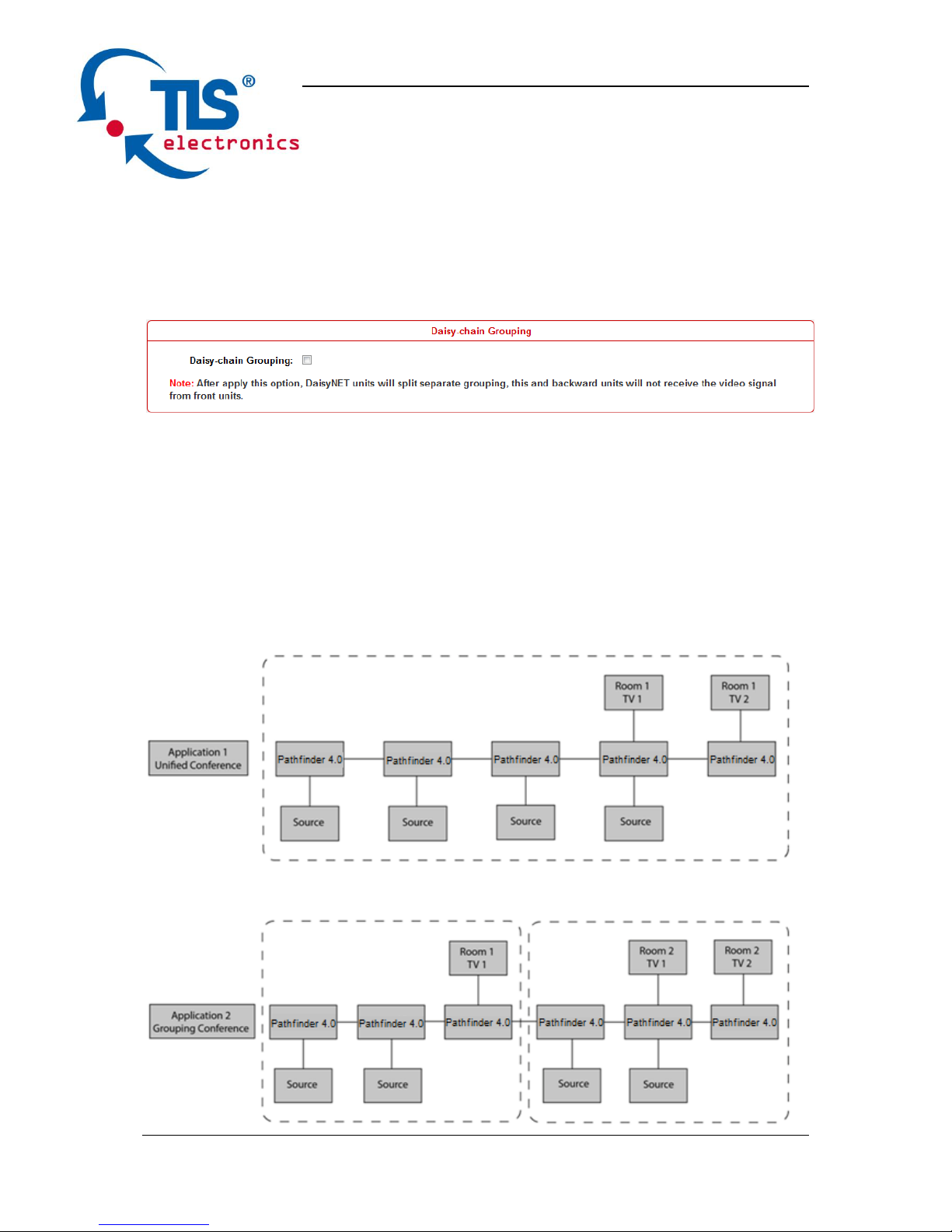
Daisy-chain Grouping
User can set PathFinder 4.0 working in grouping mode in this column.
PathFinder offers Daisy-Chain Grouping mode to meet grouping conference, in
case multiple conference groups could be set up and worked independently in
cascaded connection. By that each group could only have their local sources to
be selected or displayed, and can’t be shared to other groups.
Page 19

875800 User manual
TLS electronics GmbH Contact: info@tls-electronics.de 17
Daisy-Chain Grouping is simply activated by Telnet API or clicking the option on
the WEB GUI of device, then the video will stop to be outputted to backward
devices. After applying, backward devices can not select or display forward
sources, neither been selected or displayed by forward devices.
A cascaded chain could support multiple groups. It’s set up in WEB GUI one by
one; Telnet API is also provided to set all or each device independently to work
in grouping mode, and cancel it.
Network
The PathFinder 4.0 can be controlled over LAN. There are two IP Mode to
choose: Static and DHCP.
When users choose Static and modify the IP address then click Apply, this
window pops:
Then, it will back to the login Page:
Page 20

875800 User manual
TLS electronics GmbH Contact: info@tls-electronics.de 18
Users should login again.
When users choose DHCP and click Apply:
Note: Please ensure the device connected the router successful. Otherwise the
device will not get IP.
This window pops:
By default, the IP address to access the PathFinder is Static. User must onfigure
the IP address of each device firstly and then start the installation, in case of IP
conflicts when multiple devices connected directly.
Page 21

875800 User manual
TLS electronics GmbH Contact: info@tls-electronics.de 19
Video
This sub-menu is used to perform the following tasks:
Auto Switch
HDCP
EDID
Auto Switch
Users can enable or disable the Auto Switch function in this column.
If Auto Switch function is on, that means:
Upon detecting a new input, the device will automatically select the new input.
When an active source is removed or signal output is disabled, it will switch to
an active input by checking their priority, HDMI has a higher priority over DP,
and DP has a higher priority over VGA
Once power is restored, it will automatically switch to the source selected
before power restored.
HDCP
Users can set the HDCP ON or OFF for both HDMI and DisplayPort inputs by
WEB GUI or Telnet API, which requests specified source to output encrypted or
un-encrypted video.
FOLLOW means the source to output encrypted video.
OFF means the source to output un-encrypted video.
Note: This function is only applied to specified source which could output
encrypted or un-encrypted video depending on the display.
Page 22

875800 User manual
TLS electronics GmbH Contact: info@tls-electronics.de 20
EDID
To set the EDID by WEB GUI, adjust the EDID switch to Position 9 firstly.
For example, if user wants to write the HDMI OUT EDID of Pathfinder 1 to HDMI
IN of PathFinder 2, log in Pathfinder 1's WEB GUI, click Open Dialog button of
EDID Read, save the Bin file, and then log in PathFinder 2's WEB GUI, click
Open Dialog button of EDID Write, import the Bin file.
Note: For EDID write, HDMI/DP/HDBT supports 256 bytes only, VGA supports
128 bytes.
Control
This sub-menu is used to perform the following tasks:
CEC Controller
RS232 Controller
RS232 Pass-through
CEC Controller
PathFinder 4.0 has a is built in CEC controller, and is able to turn on/off display by
sending CEC commands to display via HDMI output port automatically.
Page 23

875800 User manual
TLS electronics GmbH Contact: info@tls-electronics.de 21
Note: This function is only effective for CEC supported and enabled displays.
CEC Auto control: Enable/disable CEC Auto-control
Delay Timing: Set the delay time of turn off display after receiving CEC
command. The range is 0~30 minutes.
CEC Manual Control: Turn on/off display by CEC command manually.
RS232 Controller
PathFinder 4.0 is built in RS232 controller, and able to save RS232 Wakeup and
Standby Commands of display and turn on/standby the display through
connected RS232 port by auto-detecting source status.
RS232 Wakeup Command: Input the RS232 Wakeup Command of connected
display, and click Save button.
Note: The command length is up to 64 characters.
RS232 Standby Command: Input the RS232 Standby Command of connected
display, and click Save button.
Note: The command length is up to 64 characters.
Baud Rate: Set the Baud Rate of connected display.
Parity Bits: Set the Parity Bits of connected display.
Page 24

875800 User manual
TLS electronics GmbH Contact: info@tls-electronics.de 22
Data Bits: Set the Data Bits of connected display.
Stop Bits: Set the Stop Bits of connected display.
Hex String: Check this option represents the command is Hexadecimal format.
End Flag: Choose the end flag of command. The command could be end with
none, "\r", "\n" or "\r\n".
RS232 Auto Control: Enable/disable RS232 Auto-control.
Delay Time (min): Set the delay time of display off after receiving RS232
command. The range is 0~30 minutes.
RS232 Manual Control: Turn on/off display manually by RS232 command.
RS232 Pass-through
RS232 pass through is used to send RS232 command manually by Web to
selected device out. Telnet API is also provided for this function.
Advanced
This sub-menu is used to perform the following tasks:
Welcome Menu
Password
System
Firmware
Page 25

875800 User manual
TLS electronics GmbH Contact: info@tls-electronics.de 23
Welcome Menu
User can change the WEB GUI logo if they need. click Browse button to browse
the Logo file, and then click Upload button.
Note: You must upload an image in PNG format with a resolution of 234x80
pixels.
Password
Input a new login password, click Apply button to save the change.
Note: Password must be 4 to 16 characters in length, alphanumeric only.
System
This sub-menu is used to perform the following tasks:
System
Automatic Logout
System
Factory Default: click this button to reset the PathFinder 4.0 to factory default
settings.
Reboot: click this button to reboot the PathFinder 4.0.
Page 26

875800 User manual
TLS electronics GmbH Contact: info@tls-electronics.de 24
Automatic Logout
Enable: Enable/Disable the automatic logout.
Delay Time(min): Select 5 means after 5 minutes it will back to login page.
Firmware
Update ARM
Step 1. click Update button.
Page 27

875800 User manual
TLS electronics GmbH Contact: info@tls-electronics.de 25
Step 2. Browse for the update file.
Step 3. Upload File OK, click Next button.
Step 4. Complete. Close this window.
Note: every time complete the upgrade, please cleaning the browser to avoid
anomalies.
Page 28

875800 User manual
TLS electronics GmbH Contact: info@tls-electronics.de 26
Update MCU
Step 1. click Update button.
Step 2. Browse for the update file
Step 3. Upload File OK, click Next button.
Page 29

875800 User manual
TLS electronics GmbH Contact: info@tls-electronics.de 27
Step 4. It takes about one minute to update. Please restart the device.
Device List Window
Page 30

875800 User manual
TLS electronics GmbH Contact: info@tls-electronics.de 28
This window displays the name and IP address of current devices.
Click the device, it will bring user to the WEB GUI of this device.
Click the Refresh to refresh the device list and WEB UI.
EDID Management
EDID (Extend Display Identification Data) is data generated from each display in
the system to communicate the capabilities of the device. The PathFinder 4.0
features an EDID copy mode that can be used when the EDID does not meet
the installation requirements. The EDID mode has several options available to
encourage device communication. Please set it to appropriate position based
on the preferred timing of connected display.
EDID
DIP Switch
EDID Description
0
HDMI/DP: 3840 x 2160@30Hz 2CH
VGA: 1920 x 1200@60Hz 2CH
1
1920 x 1200@60Hz 2CH
2
1920 x 1080@60Hz 2CH (Default)
3
1680 x 1050@60Hz 2CH
4
1600 x 900@60Hz 2CH
5
1440 x 900@60Hz 2CH
6
1360 x 768@60Hz 2CH
7
1280 x 768@60Hz 2CH
8
1024 x 768@60Hz 2CH
9
EDID by Web or API control
HDMI
AUDIOOn
Reset
DP VGA
ETHERNET
EDID
USB Charger 1,5A
Page 31

875800 User manual
TLS electronics GmbH Contact: info@tls-electronics.de 29
Package Contents
1 x Pathfinder 4.0
2 x Phoenix Male Connector (3 Pin 3.5mm)
Page 32

875800 User manual
TLS electronics GmbH Contact: info@tls-electronics.de 30
Maintenance
Clean this unit with a soft, dry cloth. Never use alcohol, paint thinner or benzene
to clean this unit.
Warranty Policy
TLS electronics products are warranted against defects in material and
workmanship for two years from the date of shipment. During the warranty
period, TLS electronics will, at its option, repair or replace products that prove to
be defective. Repairs are warranted for the remainder of the original warranty or
a 90 day extended warranty, whichever is longer.
For equipment under warranty, the owner is responsible for freight to TLS
electronics and all related customs, taxes, tariffs, insurance, etc. TLS
electronics is responsible for the freight charges only for return of the equipment
from the factory to the owner. TLS electronics will return the equipment by the
same method (i.e., Air, Express, Surface) as the equipment was sent to TLS
electronics.
All equipment returned for warranty repair must have a valid RMA number
issued prior to return and be marked clearly on the return packaging. TLS
electronics strongly recommends all equipment be returned in its original
packaging.
TLS electronics obligations under this warranty are limited to repair or
replacement of failed parts, and the return shipment to the buyer of the repaired
or replaced parts.
Limitations of Warranty
The warranty does not apply to any part of a product that has been installed,
altered, repaired, or misused in any way that, in the opinion of TLS electronics,
would affect the reliability or detracts from the performance of any part of the
Page 33

875800 User manual
TLS electronics GmbH Contact: info@tls-electronics.de 31
product, or is damaged as the result of use in a way or with equipment that had
not been previously approved by TLS electronics.
The warranty does not apply to any product or parts thereof where the serial
number or the serial number of any of its parts has been altered, defaced, or
removed.
The warranty does not cover damage or loss incurred in transportation of the
product.
The warranty does not cover replacement or repair necessitated by loss or
damage from any cause beyond the control of TLS electronics, such as lightning
or other natural and weather related events or wartime environments.
The warranty does not cover any labor involved in the removal and or
reinstallation of warranted equipment or parts on site, or any labor required to
diagnose the necessity for repair or replacement.
The warranty excludes any responsibility by TLS electronics for incidental or
consequential damages arising from the use of the equipment or products, or
forany inability to use them either separate from or in combination with any other
equipment or products.
A fixed charge established for each product will be imposed for all equipment
returned for warranty repair where TLS electronics cannot identify the cause of
the reported failure.
Exclusive Remedies
TLS electronics’s warranty, as stated is in lieu of all other warranties, expressed,
implied, or statutory, including those of merchantability and fitness for a
particular purpose. The buyer shall pass on to any purchaser, lessee, or other
user of TLS electronics’s products, the aforementioned warranty, and shall
indemnify and hold harmless TLS electronics from any claims or liability of such
purchaser, lessee, or user based upon allegations that the buyer, its agents, or
employees have made additional warranties or representations as to product
preference or use.
Page 34

875800 User manual
TLS electronics GmbH Contact: info@tls-electronics.de 32
The remedies provided herein are the buyer’s sole and exclusive remedies. TLS
electronics shall not be liable for any direct, indirect, special, incidental, or
consequential damages, whether based on contract, tort, or any other legal
theory.
RMA Policy
When returning product to TLS electronics for any reason, the customer should
fill out the official RMA form to obtain a RMA number. Without the permission or
approval, TLS electronics will be no responsible for any return.This can be
initiated by emailing or calling your related sales.
All requests are processed within 48 hours.
Standard Replacement
For customers that agree to return defective product to TLS electronics first, a
Standard Replacement option is available.
An RMA number must first be issued by sales. This RMA number will need to be
referenced on the outside of the return shipment.
Upon receipt of the defective product, TLS electronics will, at its discretion,
either repair or replace the product and ship it out in the most expeditious
manner possible. Subject to availability, the replacement product will be shipped
on the business day following receipt of the defective product.
In the event the product returned to TLS electronics has been discontinued (i.e.
the product is no longer being manufactured by TLS electronics but is still under
warranty), TLS electronics will, at its discretion, either repair or replace with
recertified product.
Once you have obtained an RMA number
After obtaining an RMA number from TLS electronics, you must send the
product - freight prepaid - to TLS electronics. The TLS electronics RMA number
must be prominently displayed on the outside of your package. If you send your
product to TLS electronics without the RMA number prominently displayed on
the outside of the package, it will be returned to you unopened.
Page 35

875800 User manual
TLS electronics GmbH Contact: info@tls-electronics.de 33
Please use a shipping company that can demonstrate proof of delivery. TLS
electronics does not accept responsibility for any lost shipments unless proof of
delivery to TLS electronics is provided.
Please note:
Product shipped to TLS electronics must be properly packaged to prevent loss
or damage in transit.
Shipping your RMA to TLS electronics using regular mailing envelopes is not
acceptable, as they do not protect the product from damage during shipping.
TLS electronics will not repair or replace a module that is shipped in such a way
that the product is not properly protected.
TLS electronics will not accept any product that has been damaged as a result
of accident, abuse, misuse, natural or personal disaster, or any unauthorized
disassemble, repair or modification.
TLS electronics GmbH
Marie-Curie-Str. 20
40721 Hilden
www.tls-electronics.de
info@tls-electronics.de
 Loading...