


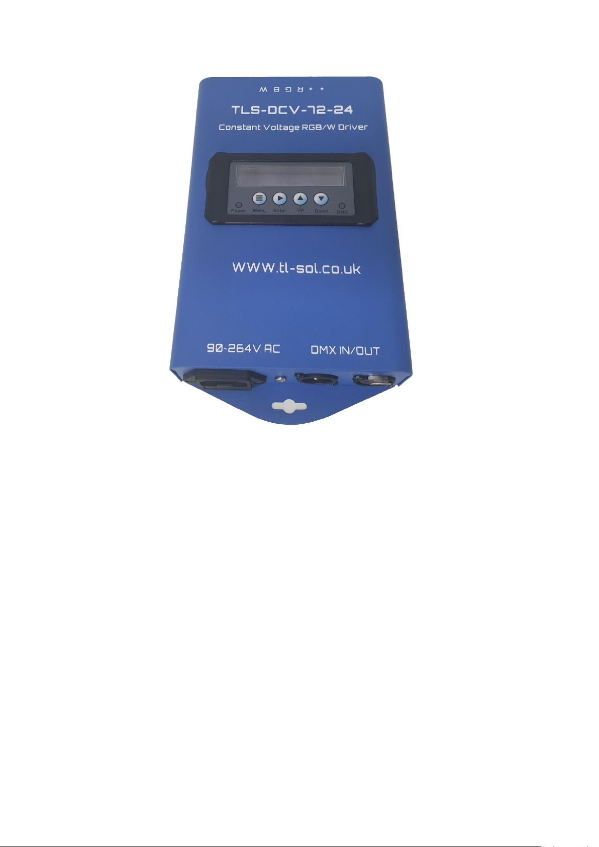
DCV-72
Digital DMX LED Tape Driver
V1.0
Contents
1.0 – Warnings .................................................................................................................................. 3
1.0.1 – Read Me .................................................................................................................................. 3
1.0.2 – Power ...................................................................................................................................... 4
1.0.3 – IP Rating .................................................................................................................................. 4
2.0 – Installation...................................................................................................................................... 5
2.0.1 – Location ................................................................................................................................... 5
2.0.2 – Fixings ...................................................................................................................................... 5
2.0.3 – Power ...................................................................................................................................... 5
2.0.4 – Data ......................................................................................................................................... 5
2.0.4.1 - DMX .................................................................................................................................. 5
2.0.4.2 - Connectors ........................................................................................................................ 5

2.0.5 – LED Connections...................................................................................................................... 5
2.0.5.1 – Correct Procedure ............................................................................................................ 5
2.0.5.2 – Short Circuit Error ............................................................................................................ 5
3.0 – User Interface Settings ................................................................................................................... 6
3.0.1 – accessing the UI....................................................................................................................... 6
3.0.2 – System Modes ......................................................................................................................... 6
3.0.3 – Changing the DMX address ..................................................................................................... 6
3.0.4 – Changing the LED mode (RGBW/RGB, CCT) ............................................................................ 6
3.0.5 – Macro Modes & DMX settings ................................................................................................ 6
3.0.6 – Sound Modes & Settings ......................................................................................................... 7
3.0.7 – Auto Modes & Settings ........................................................................................................... 7
3.0.8 – Manual Mode .......................................................................................................................... 7
4.0 UI Illumination ................................................................................................................................... 7
4.0.1 Display Illumination Settings ...................................................................................................... 7
1.0 – Warnings
1.0.1 – Read Me
WARNING FOR YOUR OWN SAFETY, PLEASE READ THIS USER MANUAL
CAREFULLY BEFORE YOUR INITIAL START-UP!
• Before the initial start-up, please make sure that there is no damage caused during
transportation.
• Should there be any damage, consult us immediately and do not use the equipment.
• To maintain the equipment in good working condition and to ensure safe operation, it is
necessary for the user to follow the safety instructions and warning notes written in this manual.
• Please note that damages caused by user modifications to this equipment are not subject to
warranty.
• This product is designed to be installed by a competent, qualified installation technician into
commercial environments.
• Never let the power cable come into contact with other cables. Handle the power cable and all
mains voltage connections with particular caution!
• Never remove warning or informative labels from the unit.
• Do not open the equipment and do not modify the unit.
• Do not connect this equipment to a dimmed power supply.
• Do not switch the equipment on and off in short intervals, as this will reduce the system’s life.
• Only use the equipment indoors.
• Do not expose to flammable sources, liquids or gases.
• Always disconnect the power from the mains when equipment is not in use or before cleaning!
Only handle the power-cable by the plug. Never pull out the plug by pulling the power-cable.
• Make sure that the power cable is never crimped or damaged. Check the equipment and the
power cable periodically.
• If the equipment is dropped or damaged, disconnect the mains power supply immediately and
have a qualified engineer inspect the equipment before operating again.
• If the equipment has been exposed to drastic temperature fluctuation (e.g. after transportation),
do not connect power or switch it on immediately. The arising condensation might damage the
equipment. Leave the equipment switched off until it has reached room temperature.
• If your product fails to function correctly, stop use immediately. Pack the unit securely
(preferably in the original packing material), and return it to TLSPixelite for service.
• Only use fuses of same type and rating.
• Repairs, servicing and power connection must only be carried out by a qualified technician.
• THIS UNIT CONTAINS NO USER SERVICEABLE PARTS.
• WARRANTY: One year from date of purchase.
OPERATING DETERMINATIONS
If this equipment is operated in any other way than that described in this manual, the product may
suffer damage and the warranty become void. Incorrect operation may lead to hazards- shortcircuit, burns and electric shocks etc. Do not endanger your own safety or the safety of others!
Incorrect installation or use can cause serious damage to people and/or property.
1.0.2 – Power
The DCV is designed with two common positive terminals, the 72W load should be spread across
these terminals evenly to ensure the phoenix connector do not burn out.
1.0.3 – IP Rating
The DCV is IP20 rated and must be used indoors and in a dry environment.

2.0 – Installation
2.0.1 – Location
Please ensure the DCV is installed in a cool dry place, operated by qualified people and always make
sure cables are not taut once installed.
2.0.2 – Fixings
The DCV requires 2 securely mounted screws to mount it to a stable surface. We recommend using
wall plugs for extra security. Items damaged by improper installation are not covered under the
warranty.
2.0.3 – Power
The DCV requires a 240V AC connection with the IEC provided. Please ensure this is pushed in fully
to avoid arcing. Please also ensure the power cable is not taut and has not been damaged during
transit.
2.0.4 – Data
2.0.4.1 - DMX
When connecting the data to a DCV, it is recommended that you use professional DMX cable to
avoid any signal issues. It is also recommended that the DMX chain is correctly terminated to avoid
data issues such as signal reflection.
2.0.4.2 - Connectors
Please use the Phoenix terminals provided to connect the DMX. If the terminals are misplaced,
please replace them with genuine Phoenix connectors. For more info call 01603 295 011.
2.0.5 – LED Connections
2.0.5.1 – Correct Procedure
When connecting Your LED tape to the DCV please ensure the LED tape matches the voltage of the
DCV, the standard voltage for a DCV is 24V DC.
Please ensure you are connecting the correct terminals to the correct wires on the LED tape, wiring
the tape incorrectly can damage both pieces of equipment.
The common positive load should be split across the two common terminals on the DCV72 to avoid
damaging the connector. You can connect a maximum of 36W per common terminal.
2.0.5.2 – Short Circuit Error
The short circuit error tells the user if a fault develops. This can be either:

1) Current overload. This is when a user has overloaded the DCV by connecting more than
300W of lighting. This may only occur at certain points when the fixture is pulling its
maximum wattage.
2) Short Circuit. This can occur when the tape is wired incorrectly or if the tape is short
circuiting because it’s damaged or faulty. Another common cause of this is when the tails at
one end of the tape are touching and creating a short circuit.
3.0 – User Interface Settings
3.0.1 – accessing the UI
To access the UI, power the DCV, hold down the “menu” key and press “enter” when prompted
whist maintaining a hold on the menu key.
This feature is on all DCV systems as a security feature to prevent accidental operator changes.
3.0.2 – System Modes
System mode enables different types of control and is set in the system mode menu which is
accessed by pressing the menu button repeatedly to cycle settings.
1. DMX – For DMX control.
2. Sound – For sound auto control.
3. Auto – For running stand alone.
4. Slave – Master Slave mode.
3.0.3 – Changing the DMX address
Cycle menu until the display reads “System Mode” and press “enter”
Once you have accessed this screen and selected the DMX Mode from DMX or WDMX* you can
press “enter” until the screen scrolls along to give you the DMX Addressing settings.
*WDMX (Wireless DMX) only available on select models.
3.0.4 – Changing the LED mode (RGBW/RGB, CCT)
Cycle menu until the display reads “System Mode” and press “enter”
Once you have accessed this screen the display will show a two-digit and a three-digit number, the
first two-digit number shows the mode as follows:
1. RGB
2. RGBW
3. Dual White (1&3 and 2&4 Grouped)
4. All Outputs Operate (1 DMX Chanel)
5. Dim + RGBW
6. RGBW + Dim + Strobe
7. Macro Mode (Described Below) MACCH
8. Assign any DMX address to any channel
3.0.5 – Macro Modes & DMX settings
For LED Mode [07] (listed above)

1. (DMX 000-025) RGB Fade + Speed + Dim
2. (DMX 026-051) RGB Step + Speed + Dim
3. (DMX 052-077) RGBW Fade + Speed + Dim
4. (DMX 078-103) RGBW Step + Speed + Dim
5. (DMX 104-129) RGB Audio Step + Dim + Sensitivity
6. (DMX 130-152) RGBW Audio Step + Dim + Sensitivity
7. (DMX 153-178) Red Strobe + Speed + Dim
8. (DMX 179-203) Green Strobe + Speed + Dim
9. (DMX 204-229) Blue Strobe + Speed + Dim
10. (DMX 230-255) White Strobe + Speed + Dim
3.0.6 – Sound Modes & Settings
For standalone Sound control
1. RGB Step Dim & sensitivity (controlled in UI)
2. RGBW Step with dim and sensitivity (controlled in UI)
3.0.7 – Auto Modes & Settings
For standalone auto control.
1. RGB fade with Dim + Speed control (controlled in UI)
2. RGB Step with Dim + Speed control (controlled in UI)
3. RGBW fade with Dim + Speed control (controlled in UI)
4. RGBW Step with Dim + Speed control (controlled in UI)
3.0.8 – Manual Mode
For manual output control.
1. Dim Output 1 (controlled in UI)
2. Dim Output 2 (controlled in UI)
3. Dim Output 3 (controlled in UI)
4. Dim Output 4 (controlled in UI)
4.0 UI Illumination
4.0.1 Display Illumination Settings
1. Go to System Settings in the menu and scroll to backlight.
2. Options are between 10 – 30 Seconds display light or Open which refers to on all the time.

For installation and technical support please contact us on 01603 295 011 or email
info@tlslighting.co.uk or visit www.tlslighting.co.uk
TLS Lighting Limited – all rights res
erved.
 Loading...