

Page 1
User’s Manual
RF Wireless Receiver
Model TL-Rx-315
315 MHz Remote Control Receiver
TL-RX-315 User Manual Contents
1. General Descriptions ....................................................................
2. Receiver Package Description ....................................................
3. Specifications .............................................................................
4. Installation & Connections ............................................................
5. Operation Instructions .......................................................... .......
6.Manual Statement for Industry Canada .......................................
7. Declaration of Conformity &
FCC Required Statement .........................................................
8. Appendix A ...............................................................................
Tin Lee Electronics Ltd. (TLE)
41 Coxwell Ave. Toronto, Ontario, Canada
416-690-3196 | fax 416-690-0932
www.tinlee.com
P. 2
P. 3
P. 3
P. 4
P. 4
P. 4
P. 5
P. 6
Printed in Canada
Specifications subject to change without notice
6/11/07
Page 2
RF Wireless Receiver Model TL-Rx-315
DESCRIPTION
Thank you for purchasing model TL-Rx-315. It is a general purpose radio frequency (RF) receiver that operates at 315 MHz. Together
with a compatible handheld RF transmitter, they provide indoor wireless remote control for a variety of TLE or third party devices.
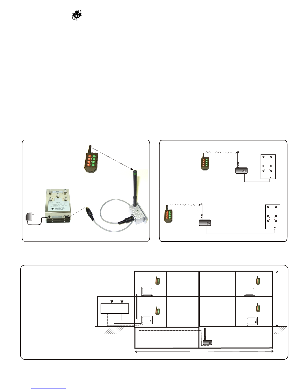
For example, figure 1 shows wireless remote control of RF signal switch (four input and 1 output) used for remote RF/Video signal
monitoring.
The function of the TL-Rx-315 is to receive RF signals sent by the RF transmitter, then translate the signals into a RS-232-compliant
output, which can be carried by a control cable to a compatible controlled device.
Application
General remote control. Figure 3 shows an example of wireless remote control of the RF Switcher used in a small building for TV/RF
signal distribution.
Save this User’s Manual - It contains important installation and operating instructions.
Please read all instructions before installing and operating.
Please note: The receiver will not operate properly if it is located in RF-shielded areas, such as behind or within metal walls or floor
obstructions.
Indoor Wireless RF
AC Adapter
RF Remote Control
CMD-HHLR-315
Controlled Device
Ex: 4x1 RF Switcher
Control cable
3
1
5
M
hz
S
i
gnal
Control Range
100 feet wireless
TL-Rx-315
3
6 feet control cable
Indoor Range - Wireless plus control cable
100 feet wireless
TL-Rx-315
TL-Rx-315
RF Receiver
400 feet control cable
Controlled
Device
INPUTS
INPUTS
(DC to 1000 Mhz)
(DC to 1000 Mhz)
A
A
Model TL-EMS 2x4
Model TL-EMS 2x4
2 Inputs x 4 Outputs
2 Inputs x 4 Outputs
RF Switch
RF Switch
2
2
1
1
OUTPUTS
OUTPUTS
LED “ON” Selects Input “A”
LED “ON” Selects Input “A”
OUTPUTS
OUTPUTS
43
43
+9VDC
+9VDC
Power Input
Power Input
Controlled
Device
INPUTS
INPUTS
(DC to 1000 Mhz)
(DC to 1000 Mhz)
A
A
Model TL-EMS 2x4
Model TL-EMS 2x4
2 Inputs x 4 Outputs
2 Inputs x 4 Outputs
RF Switch
RF Switch
1
1
OUTPUTS
OUTPUTS
LED “ON” Selects Input “A”
LED “ON” Selects Input “A”
OUTPUTS
OUTPUTS
B
B
B
B
2
2
43
43
+9VDC
+9VDC
Power Input
Power Input
Figure 1 RF Remote Control for RF Signal Switcher
HOW IT WORKS
TL-Rx-315 can receive signals from each
transmitter, and then output the signal via
control cable to a controlled device.
(e.g., TL-EMS-2x4 - two-input by fouroutput RF Switch)
Garage
Remote Control Range = 100 feet plus
control cable length (see Figure 2)
Remote controls (TL-Tx-315) are used to
select input A or B for outputs 1 through 4.
* Multiple remote controls can be used,
provided there is a two-second gap
between transmissions.
The firmware in TL-EMS-2x4 Switcher
determines Tx control functions.
Figure 3 Example Application RF Remote Control for RF Signal Switcher in small building
User Signals
CATV
Inputs A
TL-EMS 2x4
Outputs 1 2 3 4
Figure 2 Remote Control Range
Tx #3
TV
B
Tx #2
TV
Control Cable up to 400 ft.
Basement
TL-Rx-315 User’s Manual p.2
Tx #4
TV
30 feet
Tx #1
TV
TL-Rx-315
Basement
400 feet
Page 3
RF Wireless Receiver Model TL-Rx-315
RF Wireless Receiver Model TL-Rx-315
PARTS DESCRIPTION
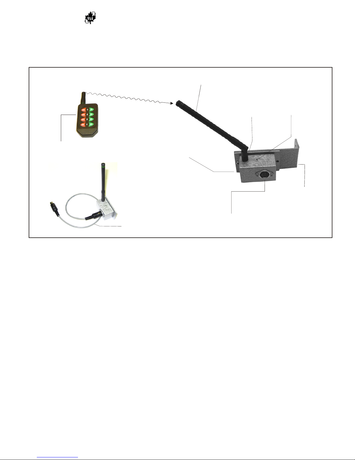
Receiver Package Description: Figure 4 shows the typical package contents for one TL-Rx-315 RF receiver. It includes an
Antenna, one Transmitter, Shielded Control Cable, Mounting Bracket, and four screws (see Figure 4).
Articulating Antenna - ANT-325-CW-HWR-RPS,
Articulating Antenna - ANT-325-CW-HWR-RPS,
1/4 wav monopole, FCC compliant
1/4 wav monopole, FCC compliant
Rapid Flashing
Rapid Flashing
Green LED:
Green LED:
Indicates Power “On”
Indicates Power “On”
and “Ready” status
and “Ready” status
Eight button Transmitter (Linx Product):
Eight button Transmitter (Linx Product):
General purpose remote control
General purpose remote control
(see note 2 and appendix A)
(see note 2 and appendix A)
DieCast Aluminum
DieCast Aluminum
Shielded Enclosure
Shielded Enclosure
RP-SMA connector
RP-SMA connector
50 ohms Impedance
50 ohms Impedance
Mounting Bracket:
Mounting Bracket:
Keep Rx 6” clear of
Keep Rx 6” clear of
objects
objects
Four position Circular
Shielded Control Cable
Shielded Control Cable
(see note 3)
(see note 3)
Four position Circular
DIN Receptacle - DC Power Input,
DIN Receptacle - DC Power Input,
RS-232 (5V, TTL) Signal Output (see note 1)
RS-232 (5V, TTL) Signal Output (see note 1)
Figure 4
Notes:
1. TL-Rx-315 Output port pin assignments and RS-232 signal output sequence, see Appendix A
2. Compatible transmitters: CMD-KEYx-315xxx, CMD-HHCP-315, CMD-HHLR-315, CMD-HHTX-315 (Linx pre-certified products).
3. Standard control cable is 6 feet. Optional control cable is available up to 400 feet , if > 400 feet cable length required, inquire.
SPECIFICATIONS
Operating Power: Voltage: +5VDC; Current: 7mA
Operating Temperature: -40 to +70ºC
Reception Frequency: 315 MHz ± 50 KHz
Reception Sensitivity: -112 dBm (for BER 10 at 1,200 bps)
Reception Range: Indoor reception is up to 100 feet from transmitter, assuming typical indoor construction materials. Range
without obstructions in the line of sight is up to 1000 feet.
Note: RF signals will not propagate through solid metal obstructions. The TL-Rx-3l5 will not function if located in shielded area.
-5
Output RS-232 signal: 5V TTL, 19.2K Baud - RS-232 signal transfer range: up to 400 feet
Dimension: Die-Cast Aluminum Shielded Enclosure: 57 x 35 x 30 mm or 2.23 x 1.36 x 1.13 in
Weight: 0.25 lbs (5 oz) (w/ antenna & mounting bracket)
Mounting Bracket Dimensions (in): 7.5 x 1.75 x 2
Configuration:
The TL-Rx-315 Receiver does not need configuration. When the controlled device is connected, and +5V DC is supplied to the Rx,
the green LED on Rx will rapidly flash to indicate power presence and readiness to receive signals.
Compatible Transmitters can be configured to have one to eight active button controls. Factory firmware will match Tx keypad to
control requirements of device. Please refer to the Linx Transmitter manual for other specific details.
TL-Rx-315 User’s Manual p.3
Page 4
RF Wireless Receiver Model TL-Rx-315
4.0 INSTALLATION and CONNECTIONS
TL-Rx-315 (Receiver) Location
The Receiver can be located close to the controlled device or far from it. For optimal performance, the receiver should be located in an
interference-free location with minimal obstructions. The remote control works best when the physical distance between the Receiver
and the Transmitter is less than 100 feet through usual indoor building materials.
Control Cable Connection
Connected one end of control cable to TL-Rx-315 and other end to the Controlled Device. The TL-Rx-315 has a circular 4-pin DIN
output jack. The control cable is a shielded four-conductor control cable with 4-pin circular DIN plug ends. Standard cable length is 6
feet but an optional extended control cable up to 400 feet in length is also available.
Install TL-Rx-315 indoors, do not immerse in water, and avoid locating the TL-Rx-315 in direct sunlight or in temperatures below
+14°F (-10°C) or above +122°F (+50°C).
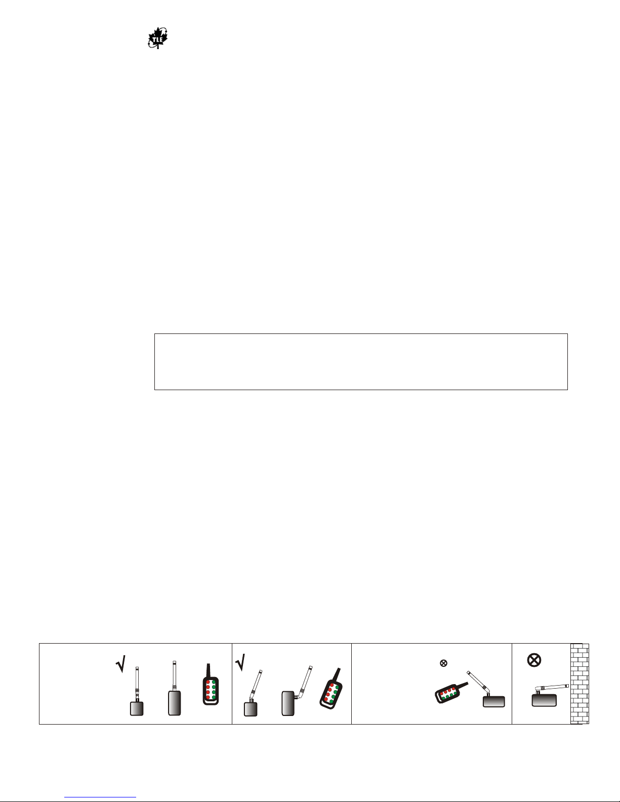
Antenna Orientation: The TL-Rx-315 includes an articulating antenna which can be adjusted for best performance (see Figure 4). In
general orientate the Receiver and Transmitter antennas perpendicular to the floor.
DO NOT modify the Receiver.
The user is cautioned that changes and modifications made to the equipment without the approval of the manufacturer could void the
user's authority to operate this equipment.
5.0 OPERATION
Operation is subject to the following two conditions: (1) this device may not cause
interference, and (2) this device must accept any interference, including
interference that may cause undesired operation of the device.
The TL-Rx-315 is powered from the controlled device. When the control cable is connected and power (+5V DC) is applied, the LED
on the receiver will flash rapidly to indicate it will receive the remote control transmissions.
Operating the Remote Control - To send a control signal, press down a button and hold for 1 second, then release.
Operating range (see Figures 2, 3)
Wireless remote control range is up 100 ft with typical indoor obstructions. The control range between TL-Tx-315 and controlled
device is up to 400 feet. This can be further increased with a signal conversion option.
Limitations:
The TL-Rx-315 and Remote Control range will vary depending on operational and environmental conditions. The Receiver and Remote
Controls will not function if located between RF shielded areas. RF signals will not travel through metal obstructions (e.g., aluminized
wall panels).
Multiple Transmitters (Tx) can operate in same reception area. All Tx use the same frequency, therefore, allow two seconds’
separation between transmissions. Note: Each Tx has a distinct address and will be recognized individually by the controlled device.
Figure 4 Range and Antenna Orientation
D
7
D
6
5
D
4
D
2
D
0
5
e
n
ts
Least range:
When Tx and Rx
antennas are
perpendicular.
Keep antenna away
from objects,
including Rx
enclosure.
D
7
D
5
D
D
2
D
C
6
D
1
M
u n
4
D
D
t
t
- 1
o
H
2
D
H
0
A
L
R
s
s
3
i
g
n
5
m
eB
n
t
s
Best Range:
When Tx and Rx
antennas are in
parallel.
And when
obstructions
between Tx and Rx
are minimized.
D6
D7
D4
D5
D2
D2
D0
D1
CMD-HHLR-315
Button Assignments
D
D
2
D
1
C
M
-
HD
B
H
ut
L
t
R
on
-
3
1
A
s
s
i
g
nm
TL-Rx-315 User’s Manual p.4
Page 5

USER’S MANUAL Model TL-Rx-315 RF Wireless Receiver
FCC Information
Declaration of Conformity
Trade Name: Radio Frequency Receiver
Model Number: TL-Rx-315
Compliance Test Report Number: B70710A1
Compliance Test Report Date: July 20, 2007
Responsible Party: Tin Lee Electronics Ltd.(TLE)
Address: 41 Coxwell Ave., Toronto, Ontario, Canada
Telephone: 416-690-3196
INSTRUCTION TO THE USER (FCC NOTICE)
This equipment has been tested and found to comply with the limits for a class B digital device, pursuant to part 15 of the FCC
Rules. These limits are designed to provide reasonable protection against harmful interference in a residential installation. This
equipment generates, uses, and can radiate radio frequency energy and if not installed and used in accordance with the instructions,
may cause harmful interference to radio communications. However, there is no guarantee that interference will not occur in a
particular installation. If this equipment does cause harmful interference to radio or television reception, which can be determined
by turning the equipment off and on, the user is encouraged to try to correct the interference by one or more of the following
measures:
·· Reorient or relocate the receiving antenna.
·· Increase the separation between the equipment and receiver.
·· Connect the equipment into an outlet on a circuit different from that to which the receiver is connected.
·· Consult the dealer or an experienced radio/TV technician for help.
In order to maintain compliance with FCC regulations, shielded cables must be used with this equipment. Operation with nonapproved equipment or unshielded cables is likely to result in interference to radio and TV reception. The user is cautioned that
changes and modifications made to the equipment without the approval of manufacturer could void the user's authority to operate
this equipment.
I the undersigned, hereby declare that the receiver specified above conforms to the above requirements.
Place: Tin Lee Electronics Ltd. Signature:
Date: August 10, 2007 Full Name: Sneva Lee
Position: Office Manager
Industry Canada Requirements
INDUSTRY CANADA (DIGITAL APPARATUS)
Interference -Causing Equipment Standard ICES-003 Issue 2
This Class B digital apparatus meets all requirements of the Canadian Interference-Causing Equipment regulations.
NOTE:
Operation is subject to the following two conditions:
(1) this device may not cause interference, and (2) this device must accept any interference, including interference
that may cause undesired operation of the device.
Product Warranty
TLE warrants theis product to be free from defects in material and workmanship for 2 years. This time
period will be based on date of purchase on invoice.
TL-Rx-315 User’s Manual p.5
Page 6
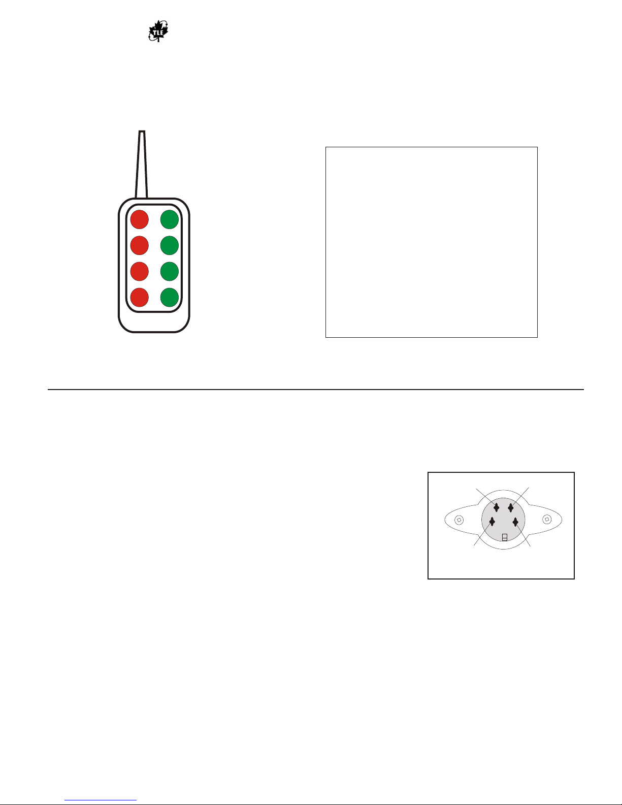
RF Wireless Receiver Model TL-Rx-315
Eight-Button Transmitter Keypad Output
D6
D7
D4
D5
D2
D2
D0
D1
Appendix A
Table1. Button pressed Information:
BIT digitButton pressed
(The sixth byte)
00000001 D0
00000010 D1
00000100 D2
00001000 D3
00010000 D4
00100000 D5
01000000 D6
10000000 D7
CMD-HHLR-315
Button Assignments
TL-Rx-315 Serial Output Connector and RS-232 Output Sequence
The TL-Rx-315 Circular DIN connector Pin assignments is as follows:
2
Pin 1 (green wire) is TX of RS-232. (5.0v, TTL)
Pin 2 (white wire) is RX of RS-232. (5.0v, TTL)
Pin 3 (black wire) is ground
Pin 4 (red wire) is for 5.0v power supply
1
Circular DIN Connector
The RS 232 Signal Output Sequence:
When the TL-Rx-315 (Rx) receives valid signal from a transmitter it will send 6 bytes of data to the RS-232 port.
The first three bytes are 3 ASCII characters “STR”, the fourth byte is the low byte of the address of the transmitter,
the fifth byte is the high byte of the address of the transmitter, and the sixth byte is Button Pressed information (see
Table 1).
After sending 6 bytes data to RS-232 port, the Rx will wait for an answer. If the answer is ASCII character 'K', the
Rx will cease sending data to RS-232 port. If the answer is ASCII character 'e', the module will send the same data
to RS-232 port again. If no answer occurs during 10 ms, the module will repeat sending the same data to RS-232
port.
3
4
TL-Rx-315 User’s Manual p.6
 Loading...