

TLC LEDLITE LTFL10PIR Installation Sheet
10 WATT PIR LED Floodlight
15-07-13
Please read these instructions before commencing installation
and retain them for future reference.
Installation Sheet LTFL10PIR
110/240V 10WIP44
• Switch off the power source before installation.
• Install a minimum distance of 1m away from ground.
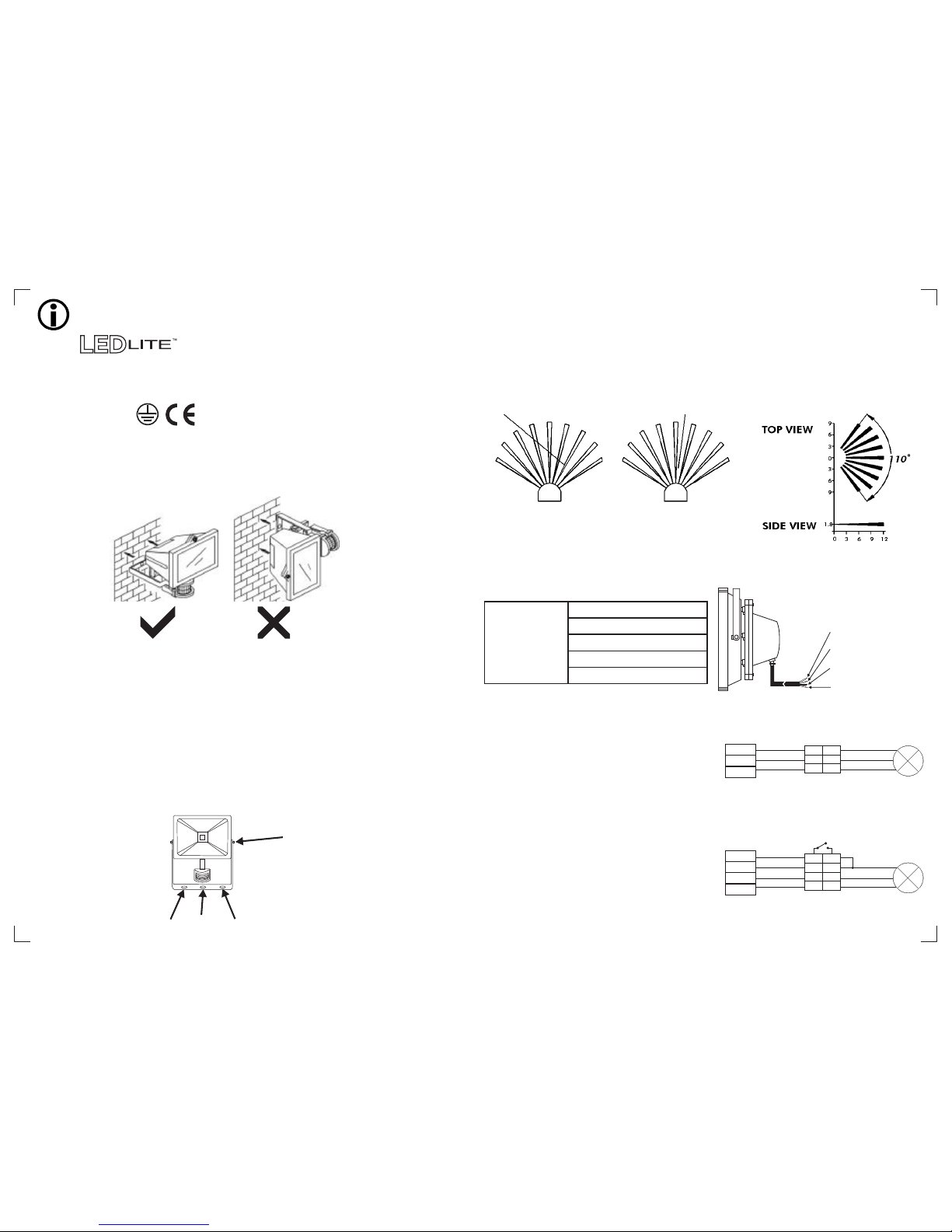
• The unit must be installed in the horizontal position (Figure 1a), not vertically (Figure 1b).
SAFETY PRECAUTIONS
1a
HORIZONTAL
1b
VERTICAL
Figure 1a & 1b
Figure 2
1 2
3
4
CHOOSING A MOUNTING LOCATION
SENSITIVITY TO MOTION
Figure 3
COVERAGE ANGLES
Figure 4
UNIT (M)
WIRING INFORMATION
240V Input Figure 5a
Wired with four
core (w/o plug)
240V Input (Figure 5a)
Brown = Live
Grey = Neutral
Green/Yellow = Earth
Black = Switch Live
MANUAL OVERRIDE FACILITY
In order to manually override the PIR sensor using an
in line switch, the Brown core (Live) is being used
as a permanent feed to the sensor and the Black core
(Switch Live) to be utilized for the switch feed.
(see Figure 5c)
Brown = Live wire - L
Grey = Neutral Wire - N
Green/Yellow = Earth wire - E
Black = Switch Live wire - SL
Switch Live
SL
S1
Manual Override wiring Figure 5c
LED
Floodlight
1. If in doubt consult a professional electrician.
2. Unscrew the floodlight from its wall bracket as indicated in Figure 2, part 4.
3. Line up the wall bracket holes and drill three holes into the wall. Use appropriate size rawl
plugs and screws to fix the bracket to the wall.
4. Screw the floodlight on to its wall bracket and tighten firmly, angling the light as required.
5. When connecting the power cable into the PIR sensor housing, please follow the wiring
instructions opposite.
6. After connecting the power supply, the installation has been completed.
INSTALLATION INSTRUCTIONS
•
• For outdoor installation, a location under eaves is preferable.
• Avoid aiming the motion sensor at pools, heating vents, air conditioners or objects that may
change temperature rapidly.
• Do not allow sunlight to fall directly on the front of unit.
• Try to avoid pointing the unit at trees or shrubs or where the motion of pets may be detected.
•
(Figure 3).
• Select a location for the unit based on the coverage angles shown in Figure 4.
For the best results, fix your sensor on a solid surface, 1.8~2.5M above the ground.
When choosing the mounting position consider that the sensor is more sensitive to motion across
the detection field (A) and less sensitive to motion directly towards the sensor (B)
SENSOR
LESS SENSITIVE
SENSOR
MORE SENSITIVE
A B
The fitting comes pre wired with a 4 core cable to
facilitate a manual override connection as an option.
Should you wish to connect the fitting as a standard
fitting please ignore the black core and connect the
other three cores as follows: Green/yellow should be
connected to earth; grey core to the neutral power input
and brown to the live power input. (see Figure 5b)
As such, referring to Fig 5a simply cancel the black
switch live connection.
STANDARD CONNECTION
Live
Neutral
Earth
L
N
E
LED
Floodlight
Standard wiring Figure 5b
A manual override facility utilizes a second live feed
in order to bypass the sensor thus allowing one to
permanently switch on your flood light.
L
N
E
L'
N
E
Live
Neutral
Earth
L
N
E
L
N
E
L'
N
E
SL L'
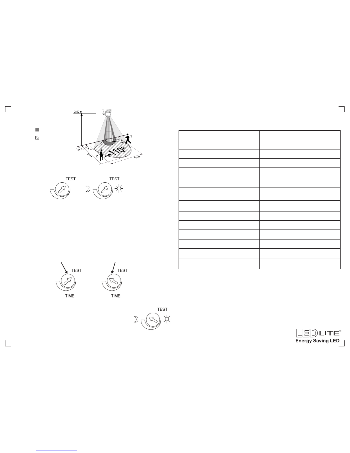
SETTING THE LIGHT SYSTEM
• Turn on the wall switch. The floodlight will turn on for about 1 minute to warm up. Then it turns off.
Walk through the detection area. The floodlight turns on when you move and turns off when you
stop. Wait for the floodlight to turn off before moving again to test the sensor.
• Adjust the motion sensor to cover the desired detection area. For a smaller coverage area, point
the sensor down; for a larger coverage area, point the sensor up.
(1) TEST MODE
•
(Figure 6).
Turn the Light control and the time control anti- clockwise to the edge – the TEST position.
Figure 6
(2) TIME ADJUSTMENT
•
• Turn the time control knob clockwise to increase (up to about 10 minutes) how long the floodlight
stays on or anti-clockwise to decrease (down to about 5 seconds) the time delay (Figure 7).
The TIME adjustment controls how long the floodlight will stay on after the motion has been detected.
Figure 7
( 3 ) LUX ADJUSTMENT
•
start operating when you set the sensor to automatic operation.
• Provisionally turn the LUX control knob to the edge clockwise at the moon
(dusk) position (Figure 8). In this provisional setting mode, the motion
sensor remains inactive during daylight. At dusk when the light level is at
the LUX required, simply set the LUX control knob to the position that the
motion sensor will become active as daylight declines.
The LUX adjustment determines at what light level the lighting system will
Figure 8
ABOUT 5 SECONDS ABOUT 10 MINUTES
TIME LUX
LUX
SPECIFICATIONS:
INSTALLATION NOTICE:
1. When installing or replacing the fixture, the electrician should be clear about the product model
number and power supply data. The power source should be isolated and switched off.
0 0
2. Working temperature: -30 - +55 , using under ventilated condition.
Power Requirement
Lighting Load
Detection Angle
Detection Distance
Swiveling Angle
Mounting Height
Time Adjustment
Lux Adjustment
Operating Temperature
Floodlight Protection Rating
PIR Protection Rating
110V - 240V
Max. 200W
Up to 110° at 20°C
Up to 12m at 20°C
Lamp Part: Vertical 90 ;
Sensor Part: Horizontal 50 ,
Vertical 40
°
°
°
Recommended 1.8 ~ 2.5m
(5.9 ~ 8.2 ft) Wall Mount
5 sec ~ 10 min
Approx. 0 ~ 1,000 Lux.
-20 C ~ +40 C° °
IP65
IP44
Protection Class Class I
Wall Switch Control
Manual Override
Walking Towards
Walking across
1
2
COVERAGE RANGE
 Loading...