

TKS K2 CombiCutter Operator's Manual
TKS Operator’s manual
1
K2 CombiCutter EN, issue 2 2013-06 988726
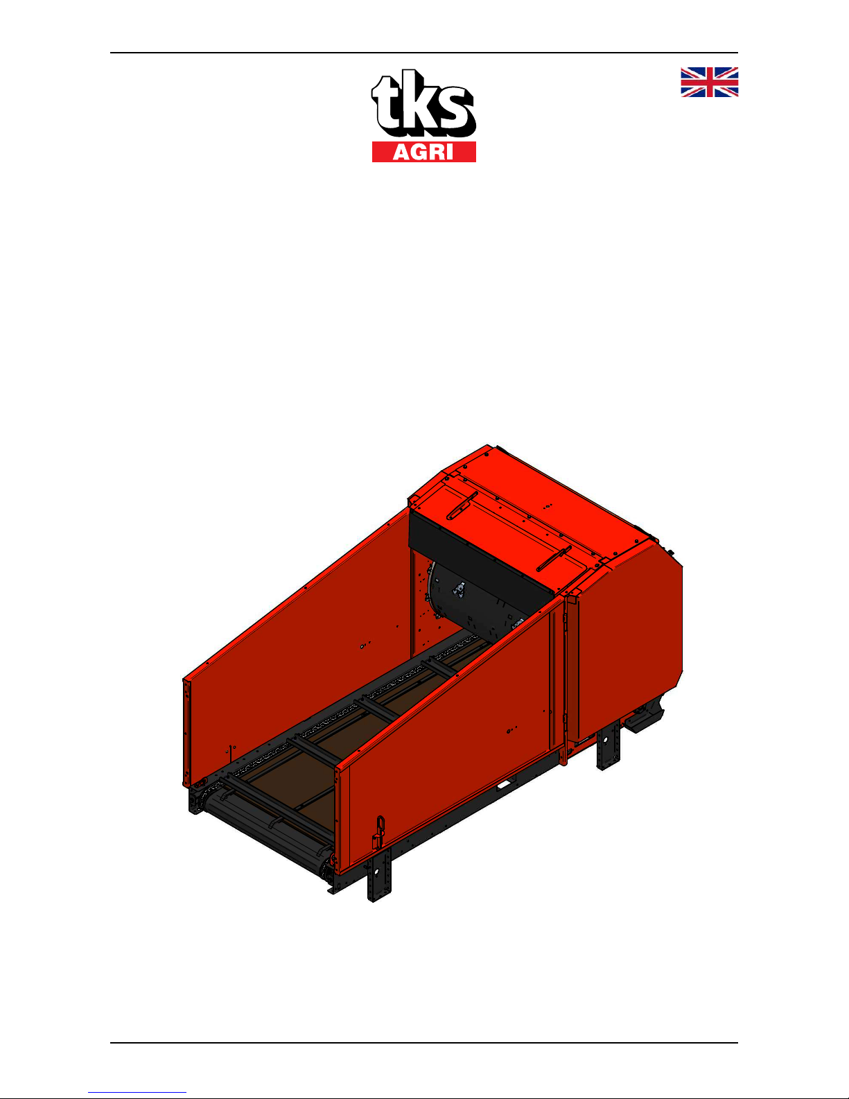
Operator’s manual
K2
CombiCutter

TKS Operator’s manual
2

TKS Operator’s manual
3
CE – Declaration of conformity
We,
T. Kverneland & Sønner AS,
Kvernelandsvegen 100
N-4355 Kverneland
Norway
declare that the product:
TKS - K2 CombiCutter
has been built in conformity with the Machine Directive 2006/42/EC and meets the
relevant fundamental health and safety requirements.
Kverneland, 20 June 2013
Tønnes Helge Kverneland
General Manager
Enter the serial number
of the machine here:
T. Kverneland & Sønner AS, manufacturer of agricultural products, reserves the right
to change the design and/ or specifi cation of its products without prior warning.
This does not imply any obligation to modify previously supplied machines.

TKS Operator’s manual
4
Guarantee
This TKS product is guaranteed against manufacturing and material defects for one year.
If the owner wishes a defect to be covered by the product guarantee, he or his representative must
inform the dealer of this when ordering parts and/ or repairs.
Claims must be reported within the guarantee period.
The dealer must complete a claims form for each case covered by a guarantee and send it to TKS
or TKS’s distributor/ importer within the 10th of the month following the one in which the defect was
reported.
The defective parts shall be marked with the claim number and be kept for up to 6 months so that
TKS or TKS’s distributor/ importer can inspect them.
Since TKS products are used outside the manufacturer’s control, we can only guarantee the
product quality, and not that it will perform its function, nor are we liable for any consequential
damage.
The guarantee is not valid if:
a) third party spare parts are used, or the product is repaired or altered without the
approval of TKS.
b) the operating and servicing instructions have not been followed.
c) the machine has been used for other purposes than those for which it is designed.
d) the damage occurs as a result of external forces such as high voltage fl uctuations due
to a low supply voltage, lightning or other electrical phenomena.
The guarantee does not cover damage due to normal wear and tear.
Offi cial safety regulations specify requirements that apply to the users/ owners and manufacturers
of this machine, relating to the careful review of safety hazards that may arise when this type of
machine is used correctly.
Therefore, TKS and our importer/ distributor are not responsible for the functioning of components
that are not shown in the spare parts catalogue for this product. TKS reserves the right to change
the design of the product without this implying any obligations in relation to previously supplied
machines.
NB! It must be possible to identify all enquiries relating to this product by the product’s serial number; see page 8 on Machine identifi cation.

TKS Operator’s manual
5
Content
CE - Declaration of conformity . . . 3
Guarantee. . . . . . . . . . . . . . . . . . . 4
Introduction. . . . . . . . . . . . . . . . . . 7
Machine identifi cation. . . . . . . . . . 8
Dimensions wide CombiCutter . . 9
Dimensions narrow CombiCutter 10
Important dimensions when . . . . . .
installing a K2 CombiCutter . . . . 11
Technical data . . . . . . . . . . . . . . 18
Model description . . . . . . . . . . . . 19
Safety . . . . . . . . . . . . . . . . . . . . . 20
1 Installing the rails. . . . . . . . . . . . . . . . 26
1.1 Recommended rail sizes on . . . . . . . . .
1-rail suspension . . . . . . . . . . . . . . . . 27
1.2 Recommended rail sizes on . . . . . . .
2-rails suspension. . . . . . . . . . . . . . . . . . . 27
2 Installing a ceiling-mounted
K2 CombiCutter . . . . . . . . . . . . . . . . . 28
2.1 Ceiling-mounted unit on . . . . . . . . . . . .
2 rails IPE 120 . . . . . . . . . . . . . . . . . . 28
2.2 Ceiling-mounted unit on . . . . . . . . . . . .
1 rail . . . . . . . . . . . . . . . . . . . . . . . . . . 28
2.3 Turning corners on a rail . . . . . . . . . 29
2.4 Installing a stationary machine . . . . 30
2.5 Installing the power supply . . . . . . . 31
2.6 Installing a power cable on a wire . . 32
2.7 Cable drum. . . . . . . . . . . . . . . . . . . . 32
2.8 Cable carriages . . . . . . . . . . . . . . . . 32
2.9 Conversion of traverser carriage . . . . . .
on rail with points. . . . . . . . . . . . . . . . 33
3 Installing the power supply. . . . . . . . 34
3.1 Copper wires 400V/230V . . . . . . . . . 36
3.2 Installing the conductor rail. . . . . . . . 37
3.3 Conductor rail with end joint . . . . . . . 38
3.4 Conductor rail with . . . . . . . . . . . . . . . .
central connection . . . . . . . . . . . . . . 45
4 Installing traverser carriages . . . . . . 48
5 Attaching the cart . . . . . . . . . . . . . . . 49
5.1 Installing the safety chain . . . . . . . . . 51
6 Installing equipment on traverser . . . .
carriages on 2-rails . . . . . . . . . . . . . . . 52
7 Installing the reservoir. . . . . . . . . . . . 55
8 Use of the machine. . . . . . . . . . . . . . . 57
9 The CombiCutter control. . . . . . . . . . 58
10 Wireless radio I/R operation K2 . . . . 59
10.1 I/R operation K2 for all functions . . . 60
11 Autofi lling K2 CombiCutter. . . . . . . . 62
12 Multi -function time relay . . . . . . . . . 64
12.1 Frequency converter. . . . . . . . . . . . 64
12.2 Motor protection device . . . . . . . . . . .
for Cutter motor . . . . . . . . . . . . . . . . . 65

TKS Operator’s manual
6
13 Frequency converter . . . . . . . . . . . . . 66
13.1 Programming and operating. . . . . . . . .
the converter. . . . . . . . . . . . . . . . . . . 67
14 Circuit diagram . . . . . . . . . . . . . . . . . 69
15 Troubleshooting the CombiCutter . . 75
16 Maintenance and care . . . . . . . . . . . . 76
17 Model description and area of . . . . . . .
use on the spreader unit. . . . . . . . . . 84
18 Use of the machine w/spreader unit 86
19 Main measurement for machine. . . . . .
with spreader unit . . . . . . . . . . . . . . . 88
20 Width adjustment on spreader unit . 89
21 Remote control . . . . . . . . . . . . . . . . . 90
22 Use of adjusment on spreader unit . .
med radiostryring . . . . . . . . . . . . . . . 91
23 Maintenance and care. . . . . . . . . . . . 92
24 Circuit diagram . . . . . . . . . . . . . . . . . 93
24.1 Circuit diagram for spreader unit . . 97
24.2 Circuit diagram for autofi lling. . . . . . 98
Recycling - waste to resource - . . . . . . . . 101
Notes . . . . . . . . . . . . . . . . . . . . . . . . . . . . 103

TKS Operator’s manual
7
Introduction
Congratulations on buying your new TKS product. You have chosen a functional, high quality
product. A network of helpful dealers will be able to advise you on its use, as well as provide
servicing and spare parts.
All TKS products are designed, tested and built in close cooperation with farmers and machine
workshops to ensure optimal effi ciency and reliability.
Please read this instruction manual carefully and familiarise yourself with the machine‘s manner
of operation before starting to use it. There are many conditions and variables that can aff ect the
machine’s functionality and manner of operation. It is therefore vital that you consider all known
conditions and adapt usage according to these. A good understanding of the machine‘s manner of
operation and performance, together with a high degree of knowledge with regard to feeding and
feed types/consistencies will ensure the best possible result. The machine is a highly advanced
feed robot that operates without the need for supervision and must be used in accordance with the
applicable instructions from the manufacturer and other regulations in force at any given time.
By being thorough and making the necessary adaptations to local conditions, you will ensure the
best possible results.
Yours faithfully
TKS AS
T. Kverneland & Sønner AS,
Kvernelandsvegen 100
N-4355 Kverneland
Norway
www.tks-as.no
e-post : post@tks-as.no
Phone : + 47 51 77 05 00
Fax : + 47 51 48 72 28
TKS Operator’s manual
8
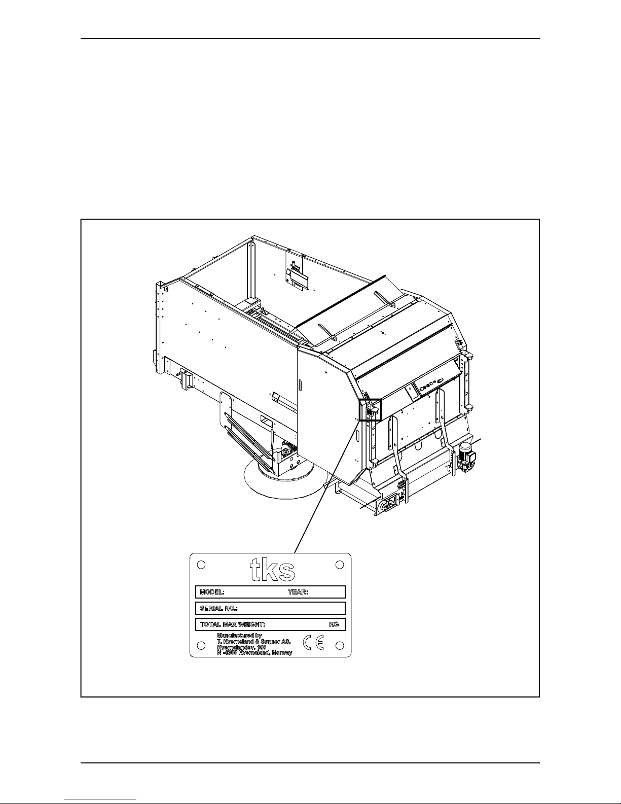
Machine identifi cation
The machine’s serial number and the address of the manufacturer are written on the machine.
See the illustration on this page.
Please use the information on the name plate when making any enquiries about spare parts or
servicing.
This product is CE marked. This mark, along with the associated written EU confi rmation, means
that the product fulfi ls current health and safety requirements, and complies with the following
directives: Machine Directive 2006/42/EC
IKO2_40
TKS Operator’s manual
9
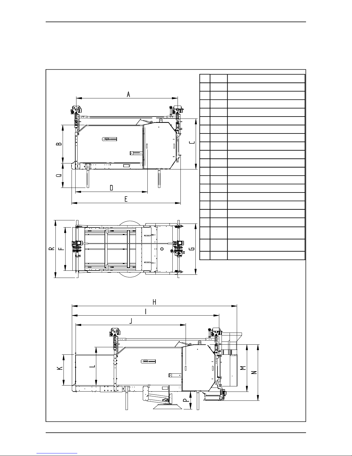
Dimensions wide CombiCutter
K2_02
All measurements are in mm
MM
A1
2670 TROLLEY (SHORT)
A2
3170 TROLLEY (LONG)
B
1185 INTERNAL
C
1580 HEIGH STD.
D1
2250 INTERNAL (LONG)
D2
1750 INTERNAL (SHORT)
E1
2922 EXTERNAL (SHORT)
E2
3422 EXTERNAL (LONG)
F
1354 INTERNAL
G
1590 EXTERNAL
I
4624 EXTERNAL 1M SECTION
J
3448 INTERNAL M. 1M SECTION
K
952 INTERNAL
L
1185 INTERNAL
M
1470 EXTERNAL
N
1755 MASHINE + CROSS CONVEYOR
P
550 WORKING HEIGHT BRUSH
Q1
400
LOADING HEIGHT WITOUT/
CROSS CONVEYOR (SHORT)
Q2
780
LOADING HEIGHT W/
CROSS CONVEYOR (LONG)
R
1800 BEAM WIDTH
TKS Operator’s manual
10
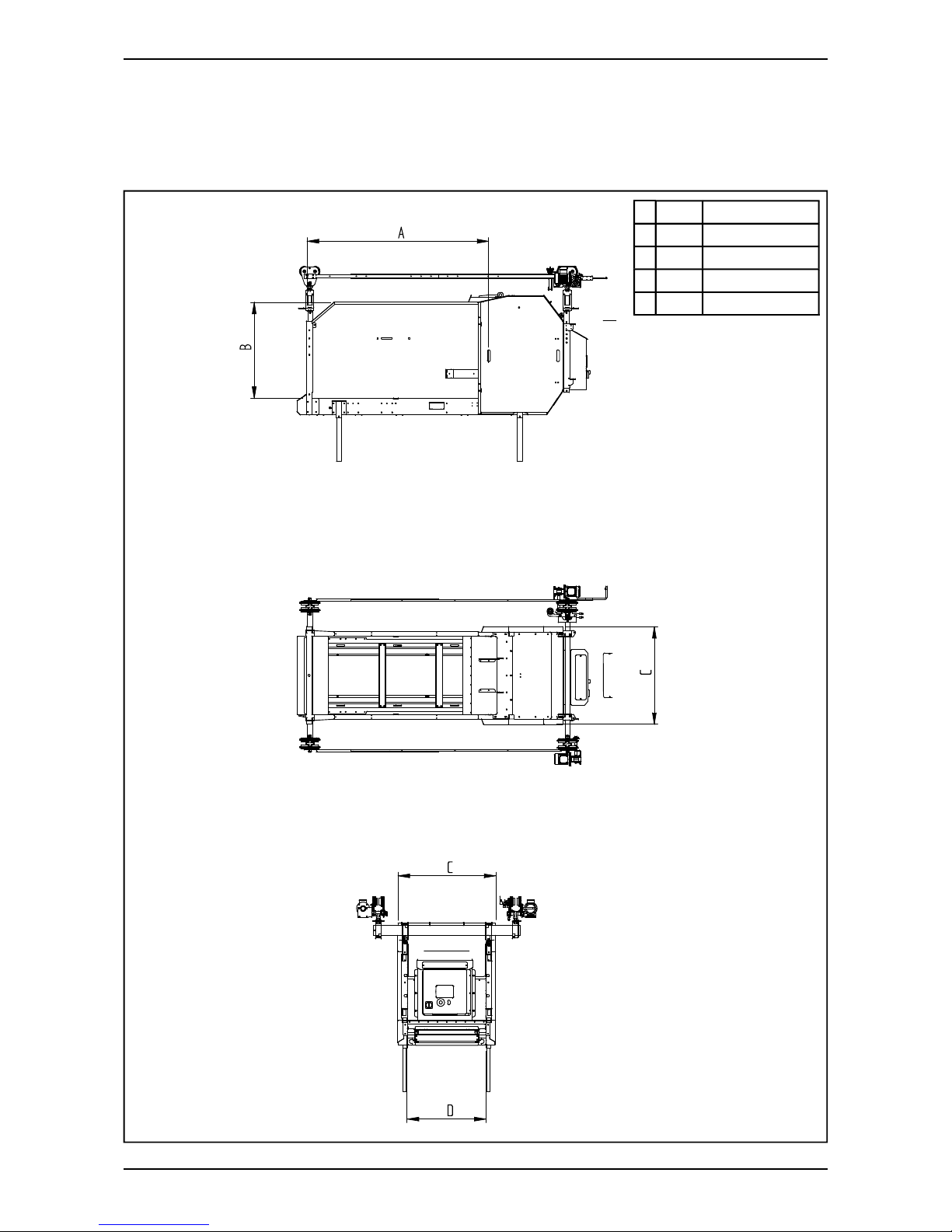
Dimensions narrow CombiCutter
K2_14
All measurements are in mm
MM
A
2244 INTERNAL
B
1202 INTERNAL
C
1202 EXTERNAL
D
964 INTERNAL
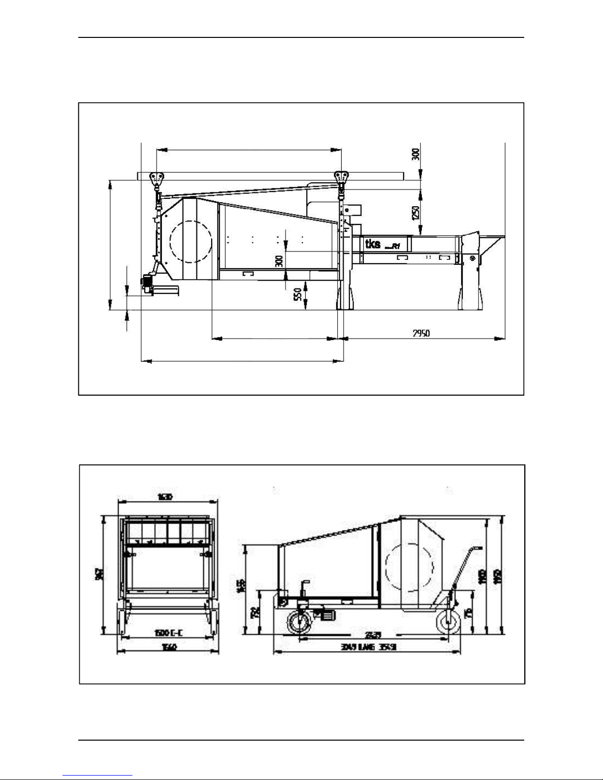
3620 Long
3120 Short
300300
2200 Long
1700 Short
TKS Operator’s manual
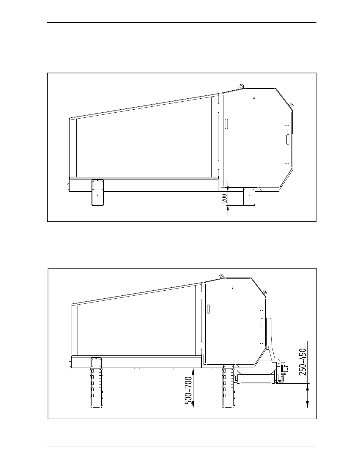
11
Important dimensions when installing a
K2 CombiCutter
Floor-cart
IK1_01
2100 2-rails
2300 1-rail
3300 Long
2800 Short
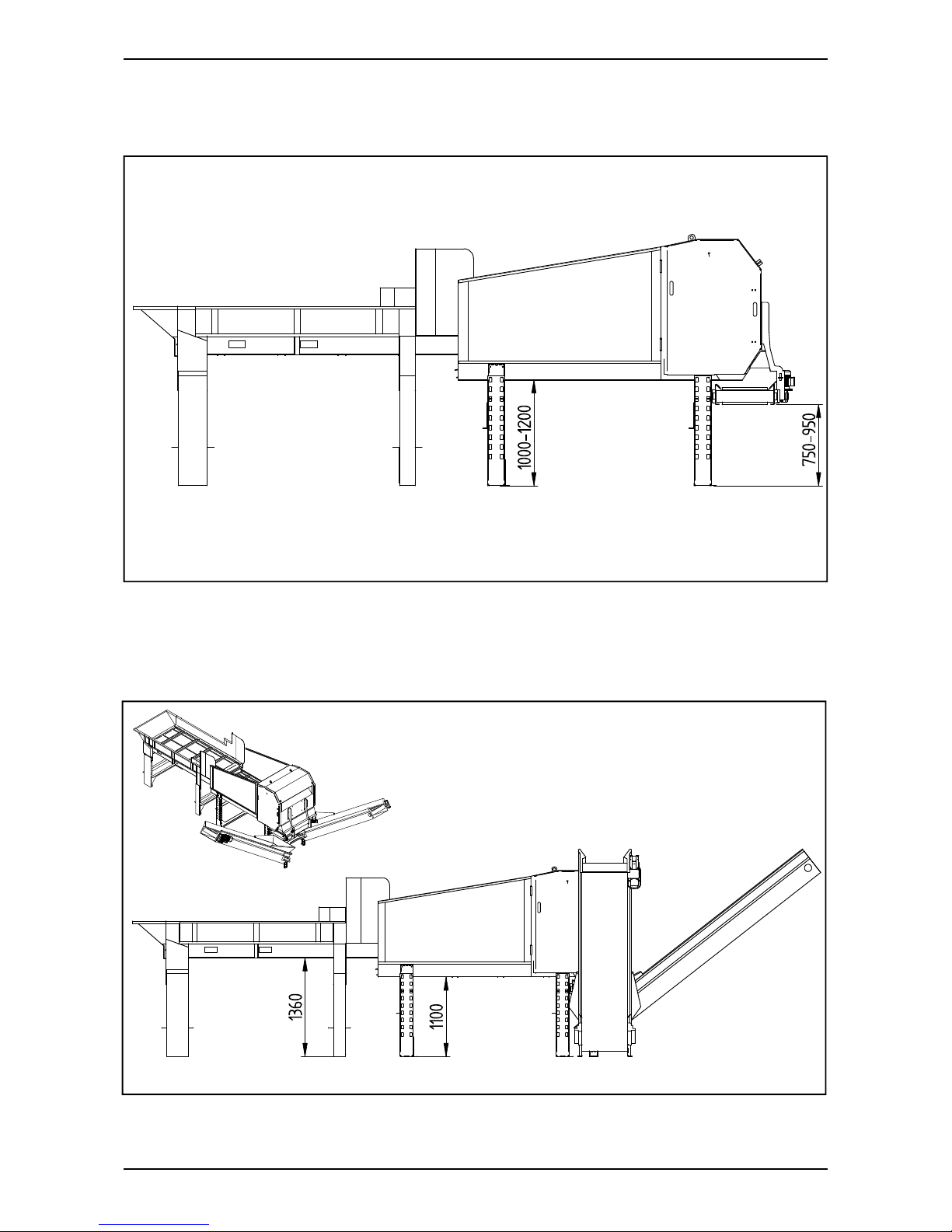
IK1_05
TKS Operator’s manual
12
All measurements are in mm
K2 CombiCutter 1600
K2 with 1.3 m cross conveyor and foot pack
K2_51
K2_52
TKS Operator’s manual
13
K2/R2 with frame cross conveyor
K2/R2 with frame, cross conveyor and conveyor
K2_53
K2_54
1
3
2
4
K2_55
TKS Operator’s manual
14
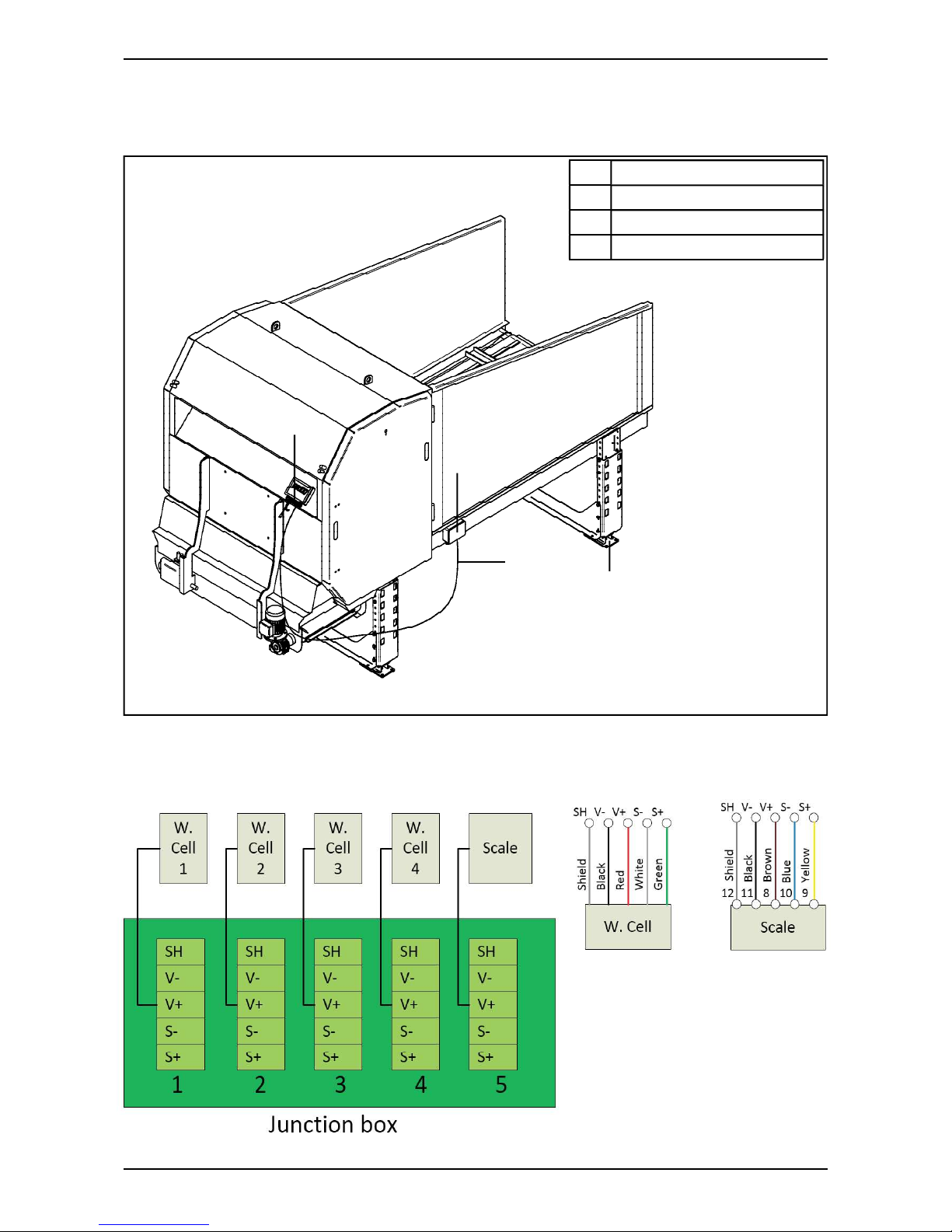
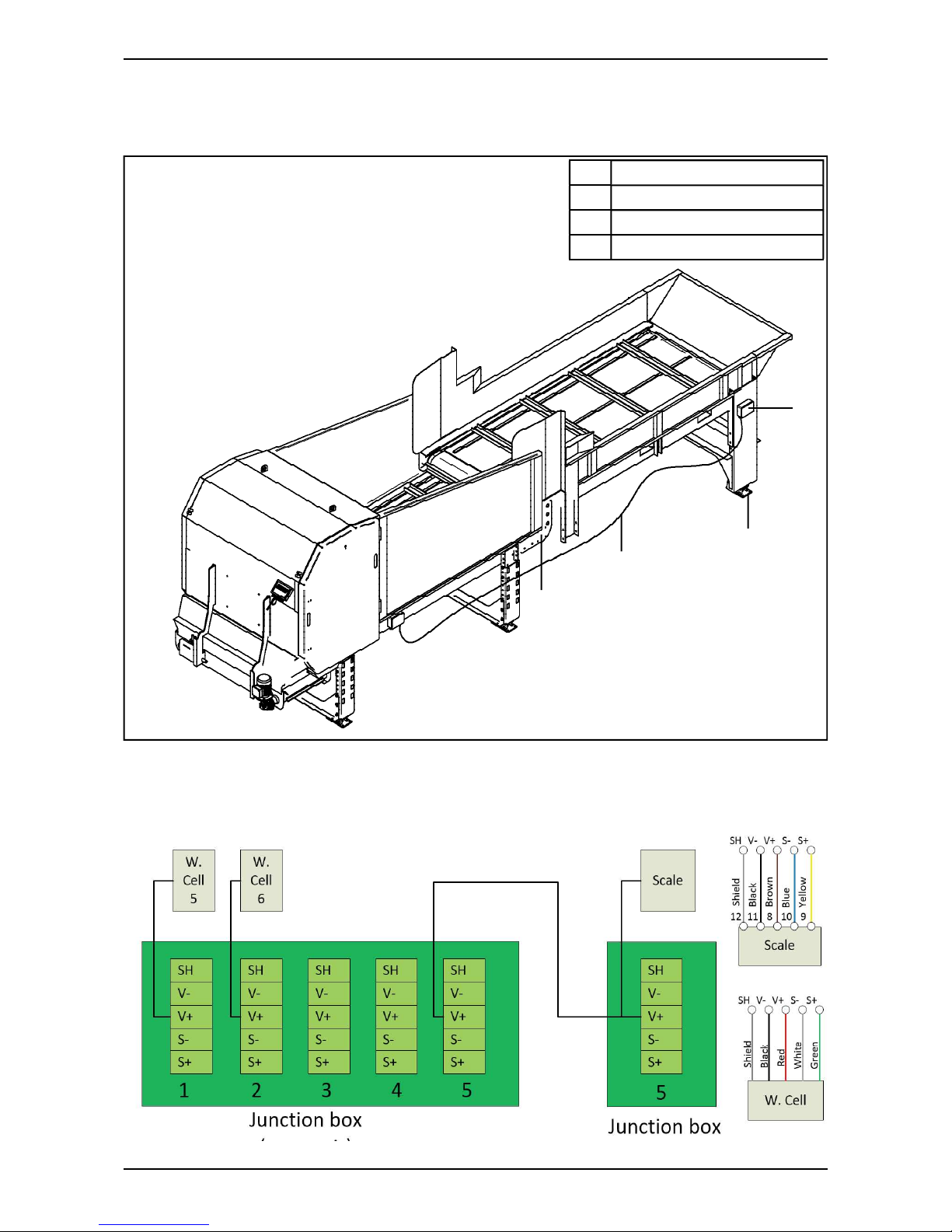
K2 with weighing cell unit
1 Weighing cell amplifi er
2 Weighing cell foot
3 Junction box 4 weighing
4 10 m cable, shielded 4x0.25
Wiring diagram Junction box

TKS Operator’s manual
15
Confi guring the weighing cell amplifi er
Code Value Function
3 15 Filter
4 150 Max. change in kg
23 4 Number of weighing cells
26 2000 Weighing cell capacity 2,000 kg
32 0 Min. voltage
34 U Voltage output (0–10 V)
38 8000 Max. weight
24 2 Convert mV to kg
20 100 Empty weight. 100
49 7 Measure frequency
1
2
3
4
TKS Operator’s manual
16
K2_55
R2 with weighing cell unit
Wiring diagram Junction box 2
1 Lug for making connection
2 Weighing cell foot 2T
3 Junction box 4 weighing
4 10 m cable, shielded 4x0.25

TKS Operator’s manual
17
Confi guring the weighing cell amplifi er
Code Value Function
3 15 Filter
4 150 Max. change in kg
23 6 Number of weighing cells
26 2000 Weighing cell capacity 2,000 kg
32 0 Min. voltage
34 U Voltage output (0–10 V)
38 12000 Max. weight
24 2 Convert mV to kg
20 100 Empty weight. 100
49 7 Measure frequency

TKS Operator’s manual
18
Technical data
WEIGHT K2 CombiCutter SHORT 1100 Kg
WEIGHT K2 CombiCutter LONG 1160 Kg
POWER
CONVEYOR BELT 0,55
KW (FREQUENCYPOWERED
SHREDDER DRUM 7,5 KW
CROSS CONVEYOR 0,9 KW
CEILING RAILS (X2) 0,40
KW (FREQUENCYPOWERED
MOTOR FOR FEED BRUSH 0,4 KW
ELECTRICITY
CONTROL CURRENT 24 V (DC)
VOLTAGE 230/240 V (N/BY 400V)
VOLTAGE TOLERANCE +/- 10%
CURRENT CONSUMPTION 230 V 30 RATED CURRENT TOT.
RECOMMENDED FUSE
40 A
CURRENT CONSUMPTION 400 V 25 RATED CURRENT TOT.
RECOMMENDED FUSE
30 A
FEED INDICATOR - CONVEYOR BELT
SHREDDER DRUM
MEASUREMENT

TKS Operator’s manual
19
Model description and area of use
The TKS CombiCutter has been designed to shred/ cut silage, round bales, square bales and most
types of forage.
The machine can be delivered as a stationary machine (placed over a feed hatch or on its own
stand).
It can also be supplied as a cart that runs along the fl oor or for mounting on ceiling rails.
These versions have two speeds.
The CombiCutter has a 750 mm diameter drum. It also has a rotating conveyor belt. The machine
is supplied with a standard knife-set:
1600 = 62 knifes
1200 = 24 knifes
The K2 CombiCutter shreds/ cuts most types of round bales and silage, with the size it cuts to
being dependent on the consistency and nature of the feed.
The machine runs very silently, and due to its large drum the main engine only requires 7.5 kW of
power. The conveyor belt has its own geared engine.
The speed of the conveyor belt can be adjusted using an converter. This gives you a lot of
fl exibility. The conveyor belt can be adjusted to the correct pressure against the drum for whatever
type of feed. The machine can be equipped with optional side doors when you want to load it with
feed.
The machine’s control panel is at the front, but during operation it can be pulled out so that you can
run the machine at the same time as seeing what is happening to the feed.
NOTE!
The recommendations contained in this instruction manual are based on normal use.
Individual users may encounter situations that require a diff erent approach from the guidelines
given here. Changes to the machine and equipment as a result of such situations do not give
grounds for claims against the manufacturer or supplier.
The climate, temperature, type of grass, time at which it was cut, baling equipment and
conservation method used are some of the issues that may aff ect the functioning and performance
of the machine.
It is important to make any necessary adjustments, and to set up the machine for the relevant
conditions. This will produce the best possible results.
Extra equipment:
Cross conveyor: 0,7m (K2 1200) - 1,0m - 1,3m - 1,7m
Double feedbrush
Section extension - wide and narrow
Pendant control
Powered ceilings
Floor cart
Auto control
Magazine
TKS Operator’s manual
20
Safety Please pay particular attention to this symbol. It
means that there is a safety risk, and describes
precautions that should be taken in order to
avoid accidents.
Before operating, adjusting or repairing the
machine, the user, technician or owner should
familiarise himself with the safety instructions
contained in this installation manual.
Pay attention and be careful when handling
agricultural machinery. Read and take note of
the safety instructions in this manual.
Safety at work is your responsibility!
General safety
instructions
Please read and understand these general
safety instructions.
There is a risk of stones being thrown
upwards and backwards when the machine
is in operation.
Use of the machine
The machine must only be used for the purpose
for which it is designed.
Operation
The operator of the machine must stay at the
end of the machine where the control panel is
located.
Providing notifi cation in the barn
The operator must familiarise himself with how
the machine works and functions, so that it can
be used safely and properly.
How the machine works
The operator must familiarise himself with how
the machine works and functions, so that it can
be used safely and properly.
Keep a safe distance
Humans and animals must be kept away from
the machine when it is in operation.
Keep your distance from working, rotating and
moving parts.
Be safety conscious
Never enter the machine when it is in operation.
When performing maintenance, disconnect the
power supply.
TKS Operator’s manual
21
Guards
Check that all shields are sound and correctly
installed. Do not start the machine before doing
this.
Damaged screens must be repaired or replaced
immediately.
Spare parts
For safety reasons we recommend that you
only use original spare parts. The use of
third-party spares invalidates the product
guarantee.
Maintenance
Ensure that the machine is properly maintained
and is kept in good condition. Never attempt to
change the mechanical workings of the
machine.
The area in which the machine is operating
Must be physically sealed off or locked to
prevent danger to humans or animals.
Control panel
The power supply must be cut off before
opening the panel.
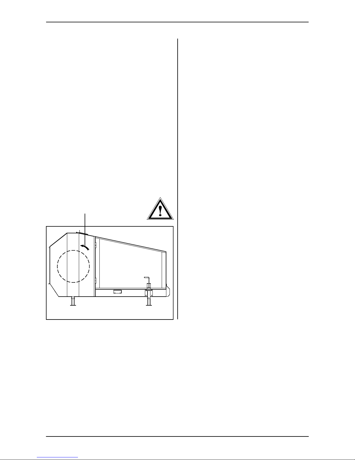
Direction of rotation
The arrow (A) indicates which way the drum
rotates.
The sticker indicating the rotational direction of
the drum should be put on the left-hand side.
NOTE!
If the rotational direction is wrong, you must
switch two phases in the main power
supply.
IK1_02
A
TKS Operator’s manual
22
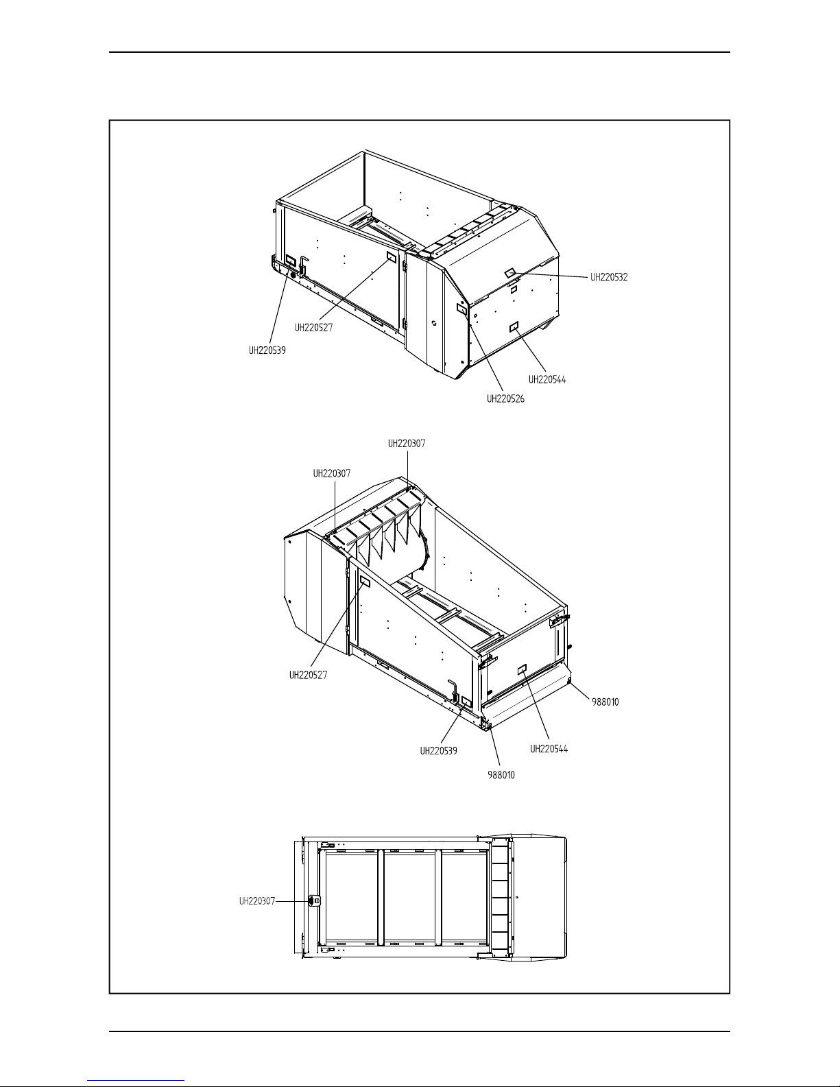
Additional safety
instructions
The machine is marked with warning
signs. If these signs are damaged, they must
be replaced.
The order number is shown on the illustrations
in this section.
See Fig. 6 for their location on the machine.
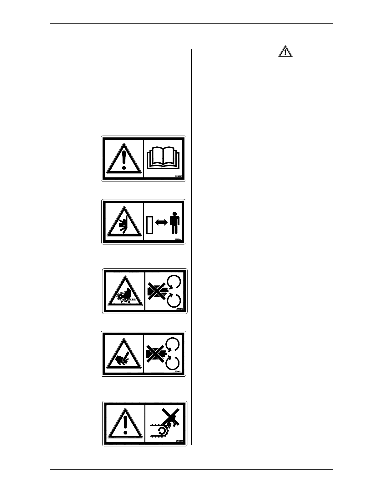
Warning sign UH220532 (Fig. 1)
Caution! Read and understand the instruction
manual before using the machine, and before
making any adjustments or performing any
maintenance.
Warning sign UH220544 (Fig. 2)
Risk of crushing injury. Keep a safe distance
from the area between the Kombikutter and
reservoir.
Warning sign UH220526 (Fig. 3)
You may damage your fi ngers if you trap them
between the chain and the chain wheel.
Warning sign UH220527 (Fig. 4)
Risk of cutting your hand. There is a risk of
cutting your hand on the drum’s knives when
the drum is in operation.
Warning sign UH220539 (Fig. 5)
Risk of breaking your fi ngers. You risk
breaking your fi ngers if you trap them between
the conveyor and the base.
Fig. 1
Fig. 2
Fig. 3
Fig. 4
Fig. 5

TKS Operator’s manual
23
Fig. 6
Warning sign 988010 (Fig. 6)
NB! The conveyor belt must be kept tight, and
the screws on the belt must be retightened.
TKS Operator’s manual
24
Overview of safety risks
IKO2_03
Fig. 7
 Loading...