

Page 1
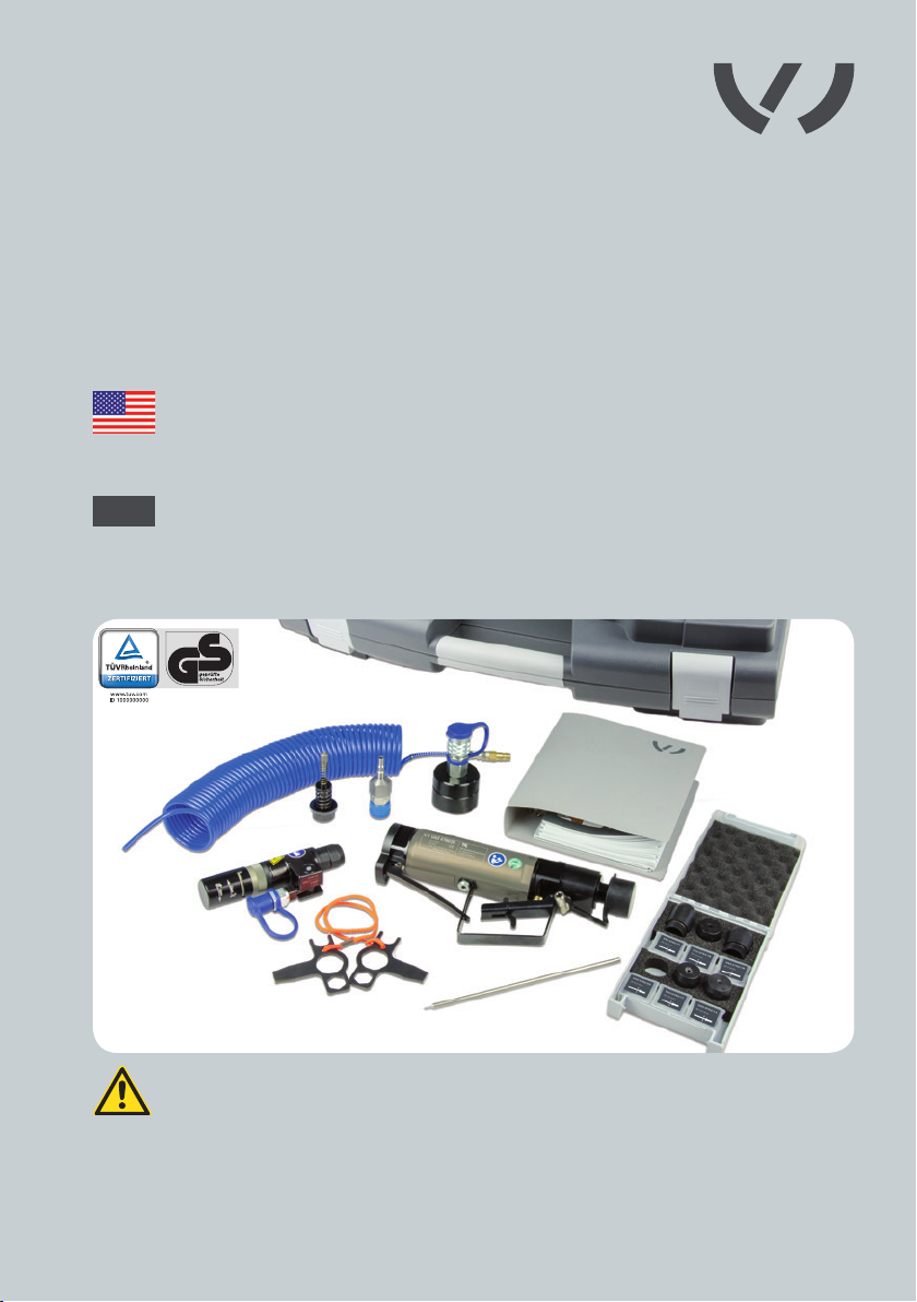
VAS 6790/2
VAS 6792
VAS 6792/1
VAS 6792/2
Pneumatic/hydraulic
blind riveting tool
BA3
Setup – Installation: Blind riveting tool
Additional information to the instruction manual
BA1 (VAS 6790/2, VAS 6792, VAS 6792/1, VAS 6792/2)
ATTENTION
This supplementary sheet serves as a supplement to the instruction manual BA1
(VAS 6790/2, VAS 6792, VAS 6792/1, VAS 6792/2) and may only be used in
conjunction with it.
Translation of original instruction manual
Page 2
?
VAS 6790/2
VAS 6792
VAS 6792/1
VAS 6792/2
Pneumatisch hydraulisches
Blindniet-Werkzeug
BA3
Inbetriebnahme – Montage: Blindnietwerkzeug
Zusatzinformation zur Betriebsanleitung BA1
(VAS 6790/2, VAS 6792, VAS 6792/1, VAS 6792/2)
ACHTUNG
Diese Montageanleitung dient als Ergänzung zur Betriebsanleitung BA1
(VAS 6790/2, VAS 6792, VAS 6792/1, VAS 6792/2) und darf nur im Zusammenhang
mit dieser verwendet werden.
Originalbetriebsanleitung
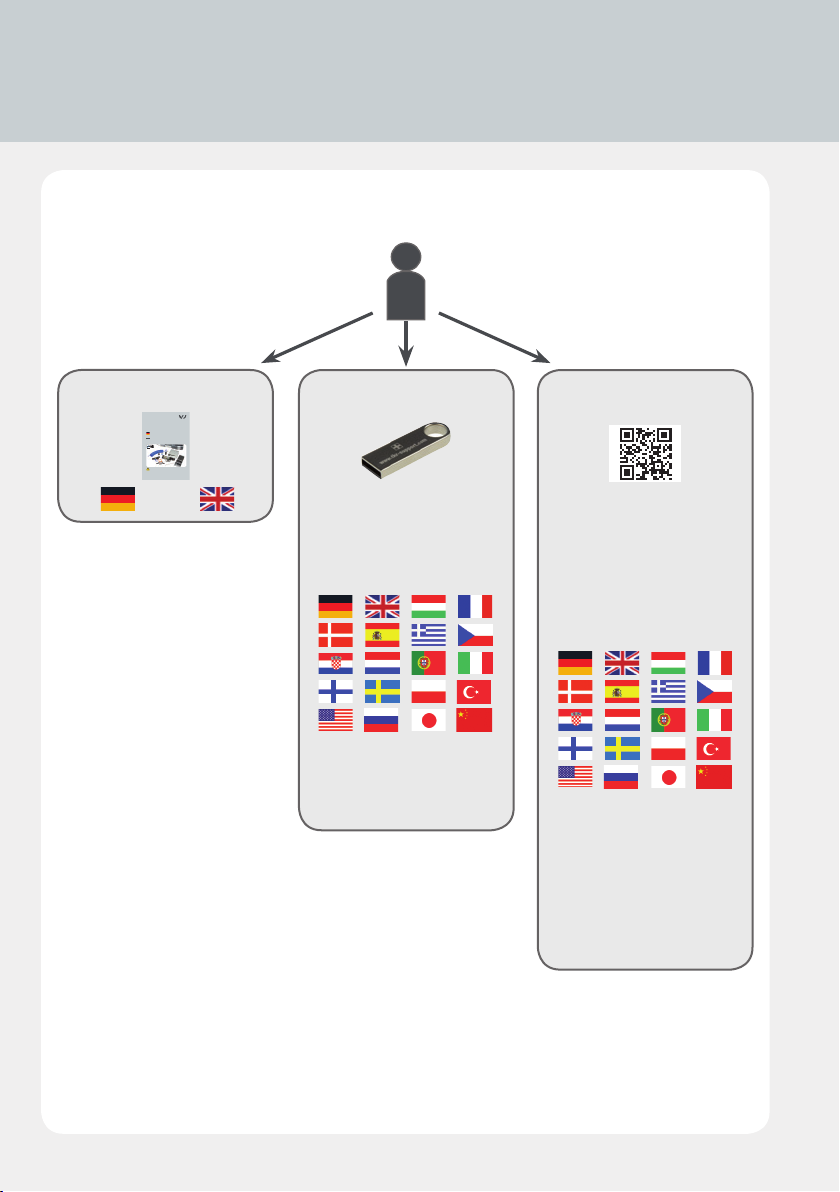
USB-Stick
Owner‘s manual
digital
www.tkr-support.comOwner‘s manual
1. Download current
owner‘s manuals
2. Support
2
Page 3

Chapter Page
1.
2.
3.
4.
Safety
1.1 Designations 5
Scope of supply
2.1 Scope of Supply and Accessories 6
2.2 Technical specications 9
2.3 Working with the blind riveting tool - basic principles 10
2.4 Maintenance 11
Technical data
3.1 Technical data 12
3.2 Device components 16
Use
4.1 Connecting the high-pressure coupling to the
Compact Booster 18
4.2 Connecting the blind riveting tool
and the Compact Booster 20
4.3 VAS 6792/2, VAS 6792/24: Screwing the extension onto
the blind riveting tool 22
4.4 Replacing the rivet head extension 27
4.5 Removing the extension 28
4.6 Replacing the conical grip 29
4.7 Connecting the spiral hose to the Compact Booster and
hose adapter 32
4.8 Connecting the pneumatic hose to the Compact Booster
and the spiral hose 33
3
Page 4

4.
Use
4.9 Using the blind riveting tool 34
4.10 Replacing the rivet head 36
4.11 Fitting the ejector 37
4.12 Using with the operating unit 39
4.13 Emptying the mandrel collector 46
4.14 Maintenance and cleaning 47
4.15 Spare parts 50
4.16 Troubleshooting 54
5.
Maintenance / Service
5.1 Disposal BA1, 60
5.2 Warranty BA1, 61
5.3 Declaration of Conformity 62
This instruction manual is protected by copyright. No use is permitted outside the strict limitations of copyright legislation without the consent of the manufacturer. Unauthorized use will
make the oender liable to criminal prosecution. This also applies to the extraction of individual
illustrations and the use of text in the extract form.
4
Page 5
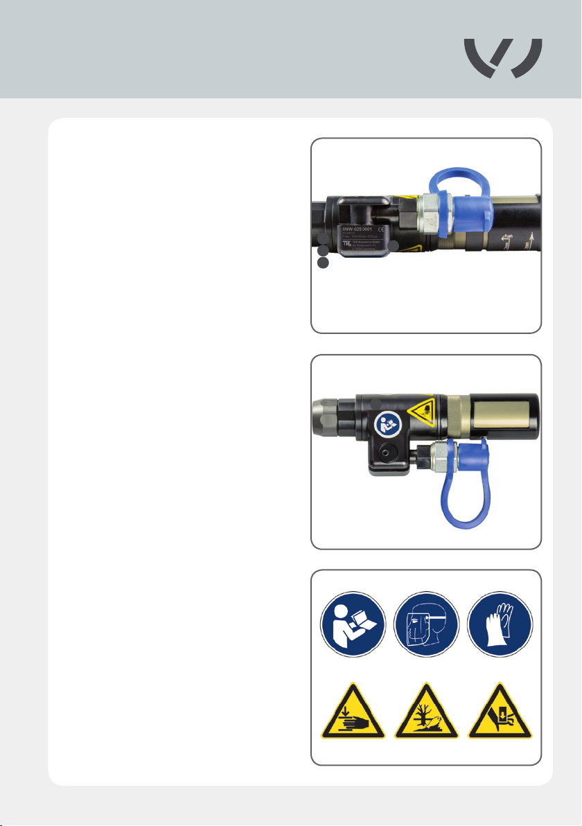
1.1 Designations
Markings on the blind riveting tool
A
B
C
D
see Fig. 1.1.3)
Manufacturer‘s identication
Serial number
Production date
Warnings (for complete view
1.1.1
A
C
D
1.1.2
B
E
1.1.3
5
Page 6
Nietmatrix
PSD-BED-00000125, Vers. 14.12
BA3
VAS 6792/11
Ø 2,0 mm
VAS 6792/13
Ø 3,0 mm
VAS 6792/12
Ø 4,0 mm
VAS 6792/14
Ø 2,6 mm
VAS 6792/10
Ø 3,4 mm
VAS 6792/27
Ø 4,0 – 4,2 mm
Ø 2,0 mm Ø 2,6 mm Ø 3,0 mm
Ø 3,4 mm
Ø 4,0 mm Ø 4,0 – 4,2 mm
Ø 4,0 – 4,2 mm
Ø 3,4 mm
Ø 3,0 mm
Ø 2,6 mm
Ø 2,6 mm
Ø 2,6 mm
Ø 2,6 mm
VAS 6792/15 VAS 6792/17 VAS 6792/19VAS 6792/16 VAS 6792/18 VAS 6792/20
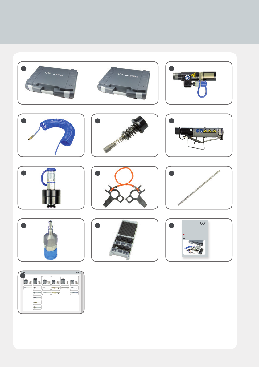
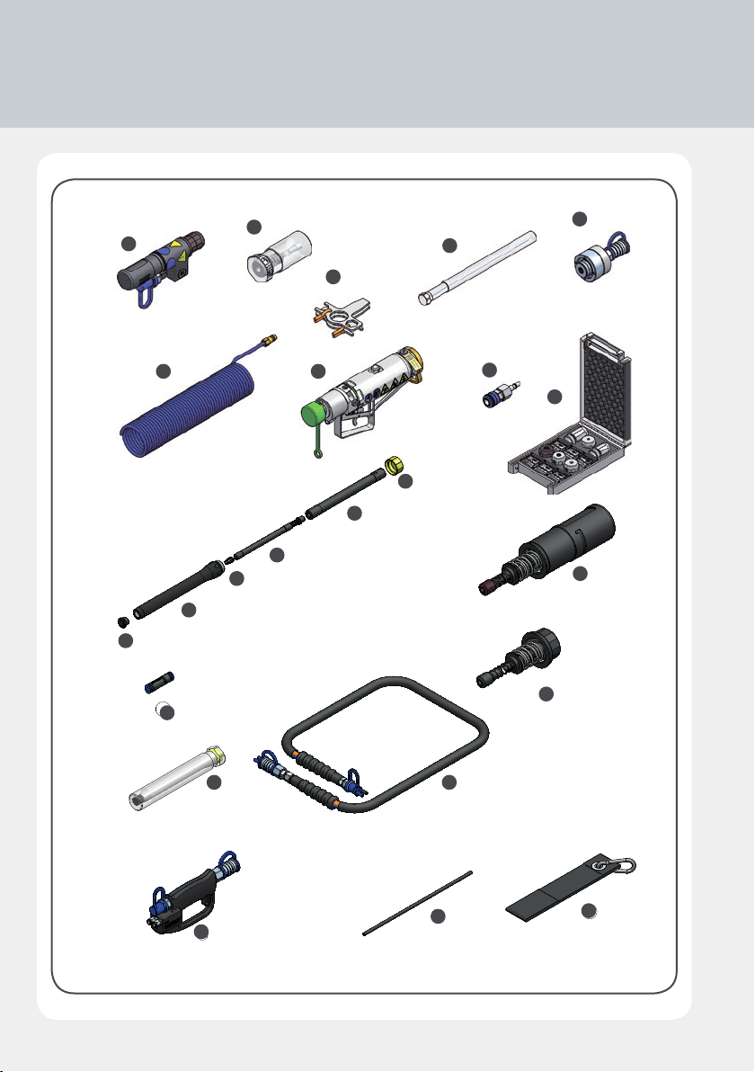
2.1 Scope of Supply and Accessories
A
C E
F
I
D
G
J K
B
H
VAS 6790/2
VAS 6792
VAS 6792/1
VAS 6792/2
Pneumatisch hydraulisches
Blindniet-Werkzeug
Bedienungsanleitung
BA3
L
6
Originalbetriebsanleitung
Page 7
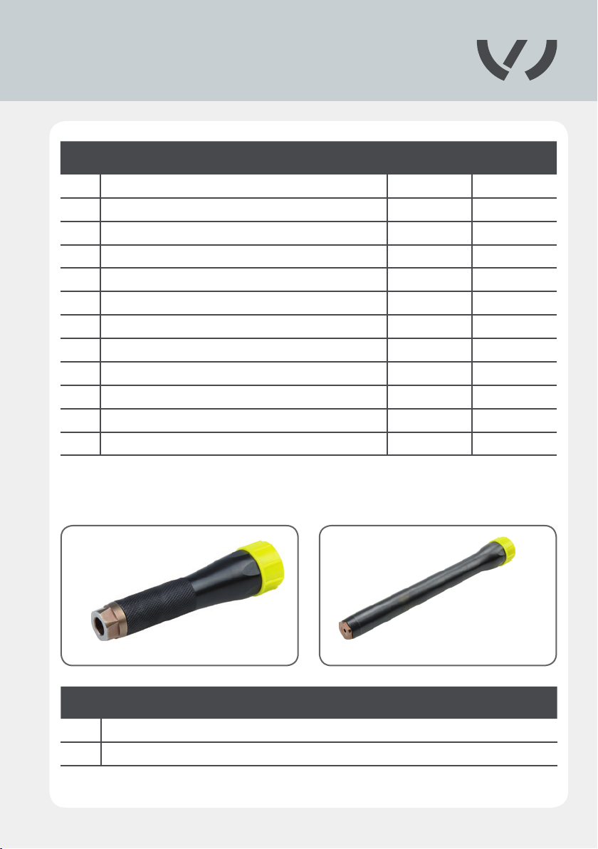
No. Item VAS 6792 VAS 6790/2
A 1 Case • •
B 1 Blind riveting tool • •
C 1 Spiral hose assembly •
D 1 Ejector •
E 1 Compact Booster •
F 1 High-pressure coupling • •
G 1 Assembly wrench • •
H 1 Assembly aid • •
I 1 Hose adapter •
J 1 Blind rivet set • •
K 1 Instruction manual • •
L 1 Rivet matrix • •
Accessories, optional
VAS 6792/2 VAS 6792/24
No. Item
M Extension, 59 mm
N Extension , 160mm
7
Page 8
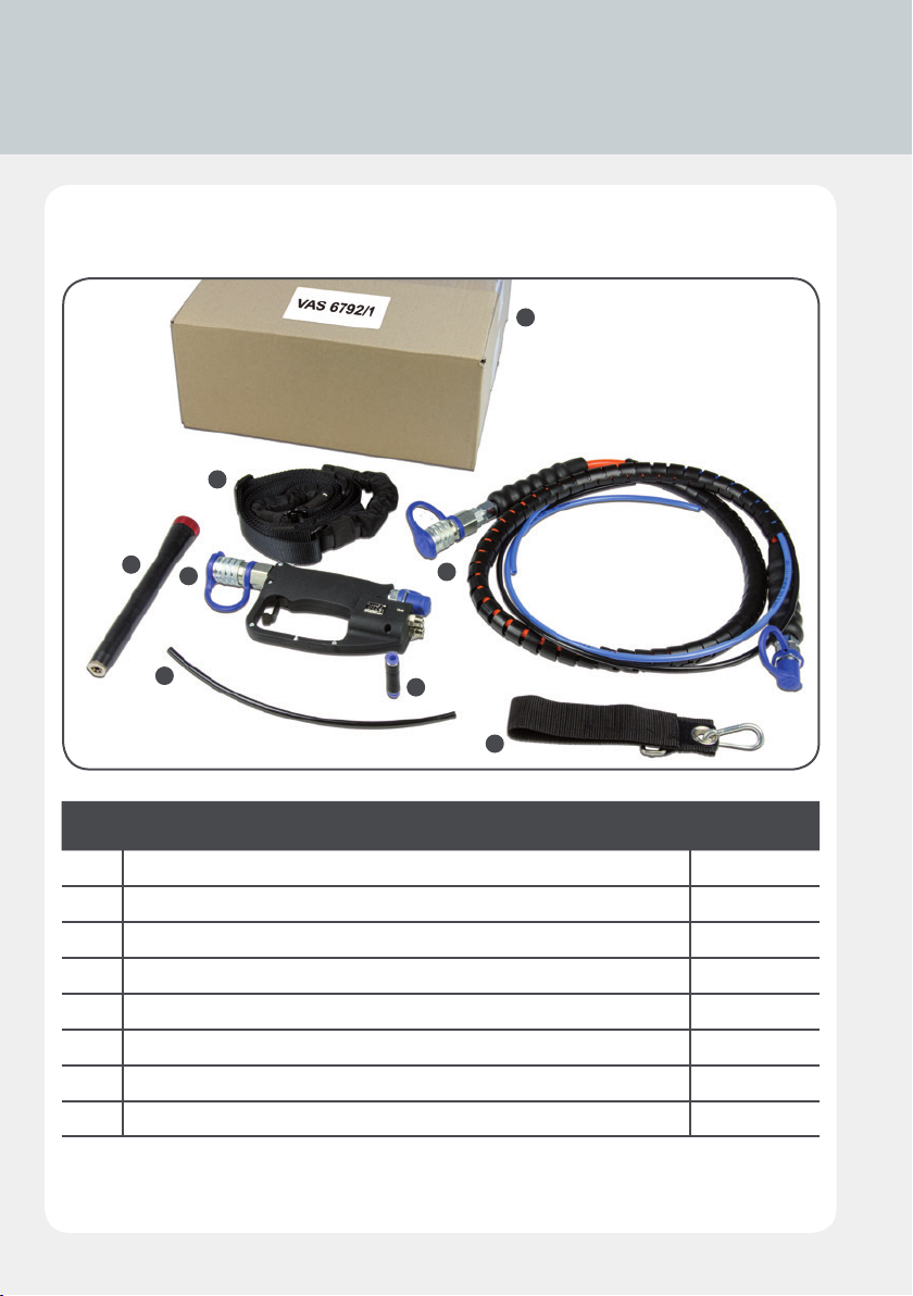
2.1 Scope of Supply and Accessories
Accessories set, optional
V
P
O
R
T
VAS 6792/1
Q
S
U
No. Item VAS 6792/1
O Extension, 160 mm •
P Carrying strap •
Q Hose assembly •
R Operating unit •
S Plug connector •
T Pneumatic hose •
U Supporting belt •
V Cardboard box •
8
Page 9
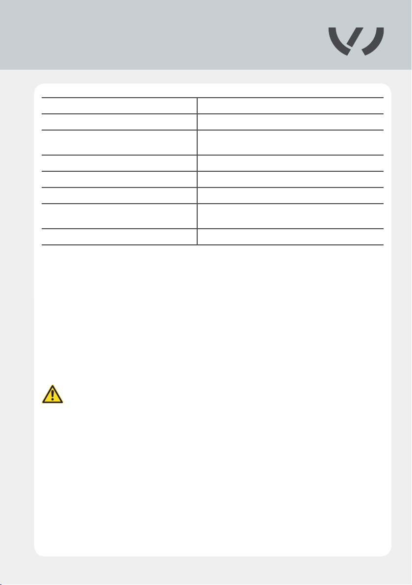
2.2 Technical specications
Travel 20 mm
Setting force 24500 N at 6 bar
Weight 0.8 kg (without hose and operating unit)
Hydraulic operating pressure max. 600 bar
Pneumatic operating pressure 6 bar
Ambient temperature 5 – 50 °C/41 – 122 °F
Prescribed safety clothing
Drive unit Compact Booster
Protective gloves, eye protection, long-sleeved
working clothes, close tting at the neck
The pneumatic/hydraulic blind riveting tool was specially developed for all common
riveting operations on thin sheet metal.
The blind riveting tool must only be used with the pneumatic-hydraulic blind
riveting tool Compact Booster.
The blind riveting tool is connected to the Compact Booster using a high-pressure
coupling.
9
Page 10
2.3 Working with the blind riveting tool - basic
principles
Risk of injury
Route all supply lines in a manner that prevents people from tripping over them.
Correctly route and attach the compressed air hose. If a compressed air hose whips
around wildly, it could cause severe bodily injury.
Before starting work, check the preset air pressure! Incorrectly set air pressure
could cause equipment damage or bodily injury!
Max. air pressure
Make sure that the maximum permissible operating air pressure of 6 bar / 87 psi
is never exceeded. Check the setting of the pressure regulating valve before each
riveting operation!
Clean compressed air
Make sure that the pressure generator is only supplied with clean and dry compres-
sed air. Moisture and contamination could cause equipment malfunction and/or da-
mage. Only use compressed air of quality class 2 as per ISO 8573-1.
10
Always disconnect the riveter from the compressed air when leaving your
workstation!
Warranty
The manufacturer accepts no liability for damage or injury caused by improper re-
pair or use of foreign replacement parts.
Incorrect usage of the blind riveting tool that leads to equipment damage invali-
dates the warranty.
The compressed air supply must be disconnected from the equipment before
any adjustment or maintenance work is performed.
Page 11

2.4 Maintenance
The tool‘s hydraulic system, pneumatic control systems, hoses and couplings
must all be kept free of dirt and other contamination. Foreign bodies in the
hydraulic uid or in the control air will cause the tool system to malfunction.
All maintenance and service work on the blind riveting tool must only be per-
formed with the pressure generator disconnected.
Under normal circumstances, maintenance of the blind riveting tool is restricted to
4.16
regular cleaning and replacement of the conical grips.
All other necessary maintenance work and/or repairs must be performed by the ma-
nufacturer or properly trained personnel only.
The user must only perform the maintenance and repair measures outlined in this
instruction manual.
Maintenance and repair work not covered in this instruction manual may only be
performed by professionals who have been correctly trained by TKR. For further in-
formation on servicing and training, please contact us at our Service address:
TKR Spezialwerkzeuge GmbH
Service
Am Waldesrand 9-11
D-58285 Gevelsberg (Germany)
Phone: +49 23 32 666 07 - 0
Fax: +49 2332 666 07 - 941
E-Mail: [email protected]
Download-Service
www.tkr-support.com
11
Page 12
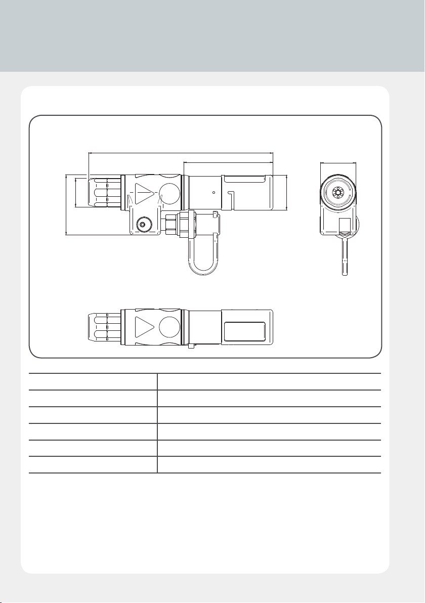
3.1 Technical data
Blind riveting tool with mandrel collector
3.1.1
179
28
O
58
Overall length 179 mm
Length of mandrel collector 87 mm
Height 58 mm
Width 35 mm
Ø Mandrel collector 34 mm
Ø Rivet head 28 mm
87
34
O
35
12
Page 13
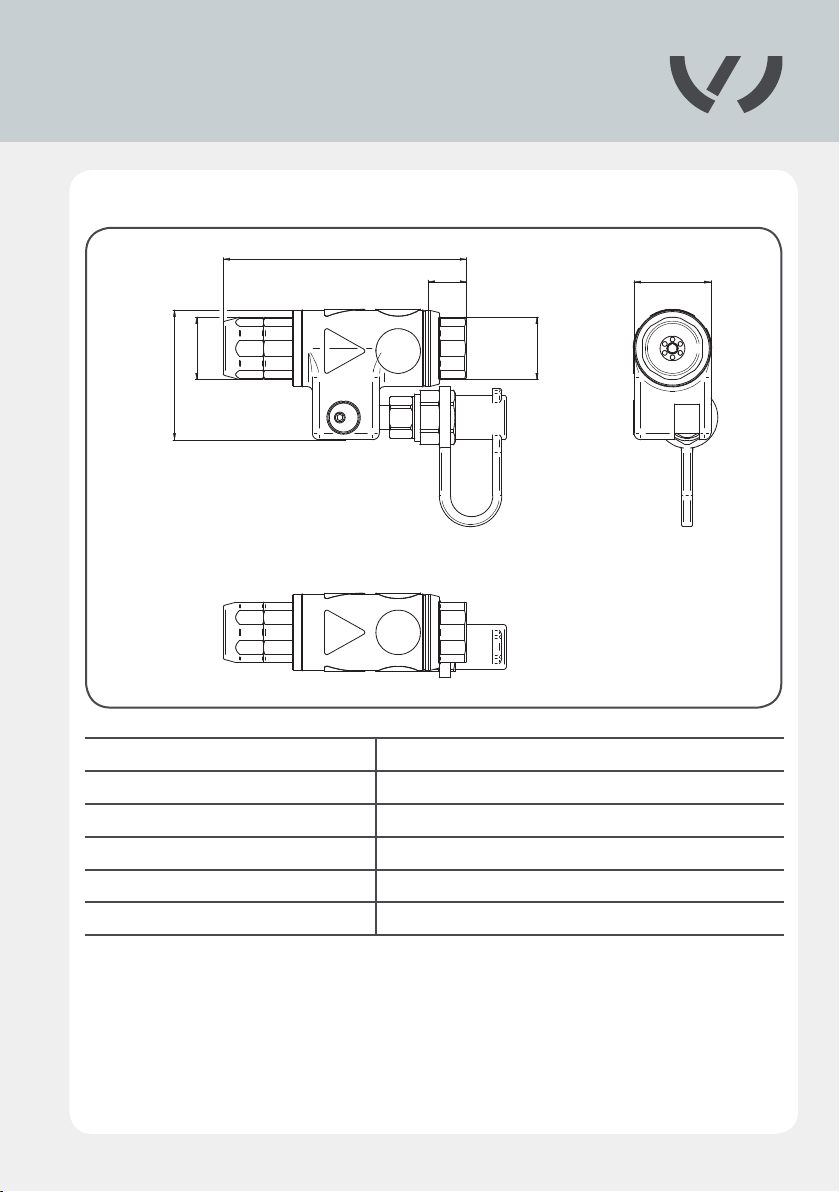
Blind riveting tool with ejector
3.1.2
28
58
109
Overall length 109 mm
Length of ejector 17 mm
Width 35 mm
Height 58 mm
Ø Ejector 38 mm
Ø Rivet head 28 mm
17
28
O
35
13
Page 14
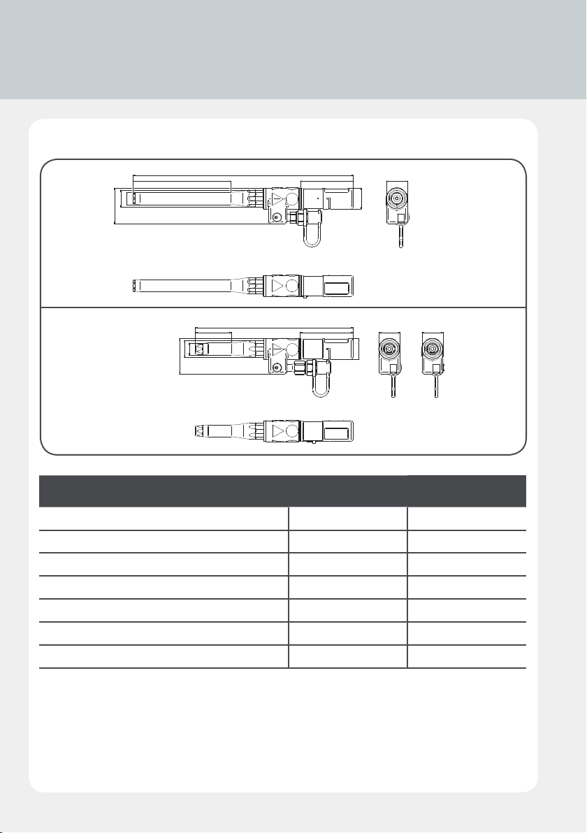
58
360
260.2
35
3.1 Technical data
Blind riveting tool with mandrel collector and extension
3.1.3
28
20
O
O
87160
35
34
O
VAS 6792/24
59
28
20
O
O
58
87
35
34
O
VAS 6792/2
VAS 6792/24 VAS 6792/2
Overall length 360 mm 260.2 mm
Height 58 mm 58 mm
Ø Rivet head 20 mm 20 mm
Width 35 mm 35 mm
Length of straight housing 160 mm 59 mm
Length of mandrel collector 87 mm 87 mm
Ø Mandrel collector 34 mm 34 mm
14
Page 15
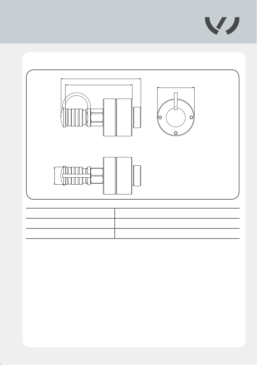
High-pressure coupling
3.1.4
27.2O
125
104
Length 125 mm
Ø Coupling 58 mm
Ø Connection 27 mm
O58
15
Page 16
Q
O
Q
O
R
S
U
Q
F
Q
U
3.2 Device components
3.2.1
2
1
5
4
3
6
7
8
9
A
10
B
11
C
12
G
16
E
14
D
13
S
18
O
19
Q
20
F
15
I
17
16
21
R
T
22
23
U
Page 17

No. Title
1 Blind riveting tool
2 Front ejector
3 Assembly wrench
4 Assembly aid
5 High-pressure coupling
6 Spiral hose
7 Compact Booster
8 Hose adapter
9 Blind rivet set
10 Protection cover
11 Protection cover
12 Extension rod
13 Rivet head
14 Extension casing
15 Mandrel collector
16 Conical grip
17 Ejector
18 Plug connector
19 Extension 160 mm
20 Hose package
21 Operating unit
22 Pneumatic hose
23 Supporting belt
17
Page 18
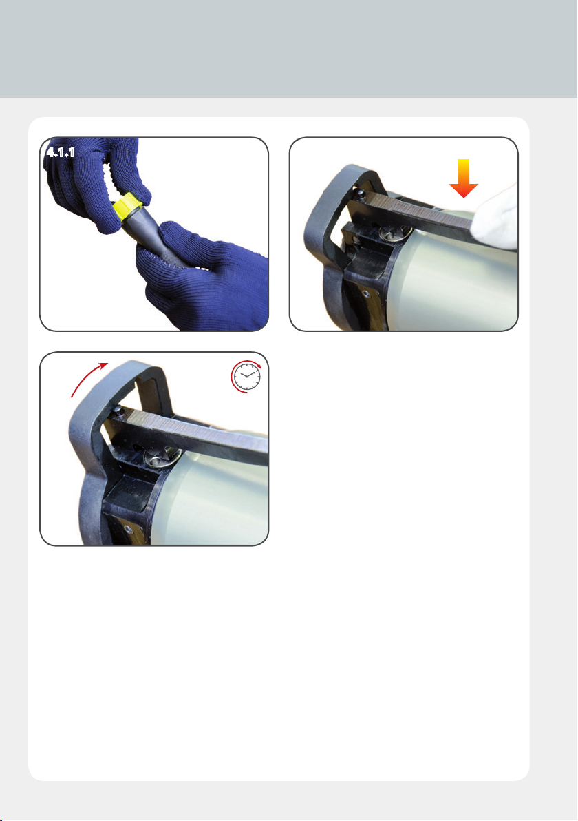
4.1 Connect the high-pressure coupling to the
Compact Booster
4.1.1 4.1.2
4.1.3
4.1.1 – 4.1.3
Press the lever on the Compact Booster to
turn the locking mechanism clockwise.
18
Page 19
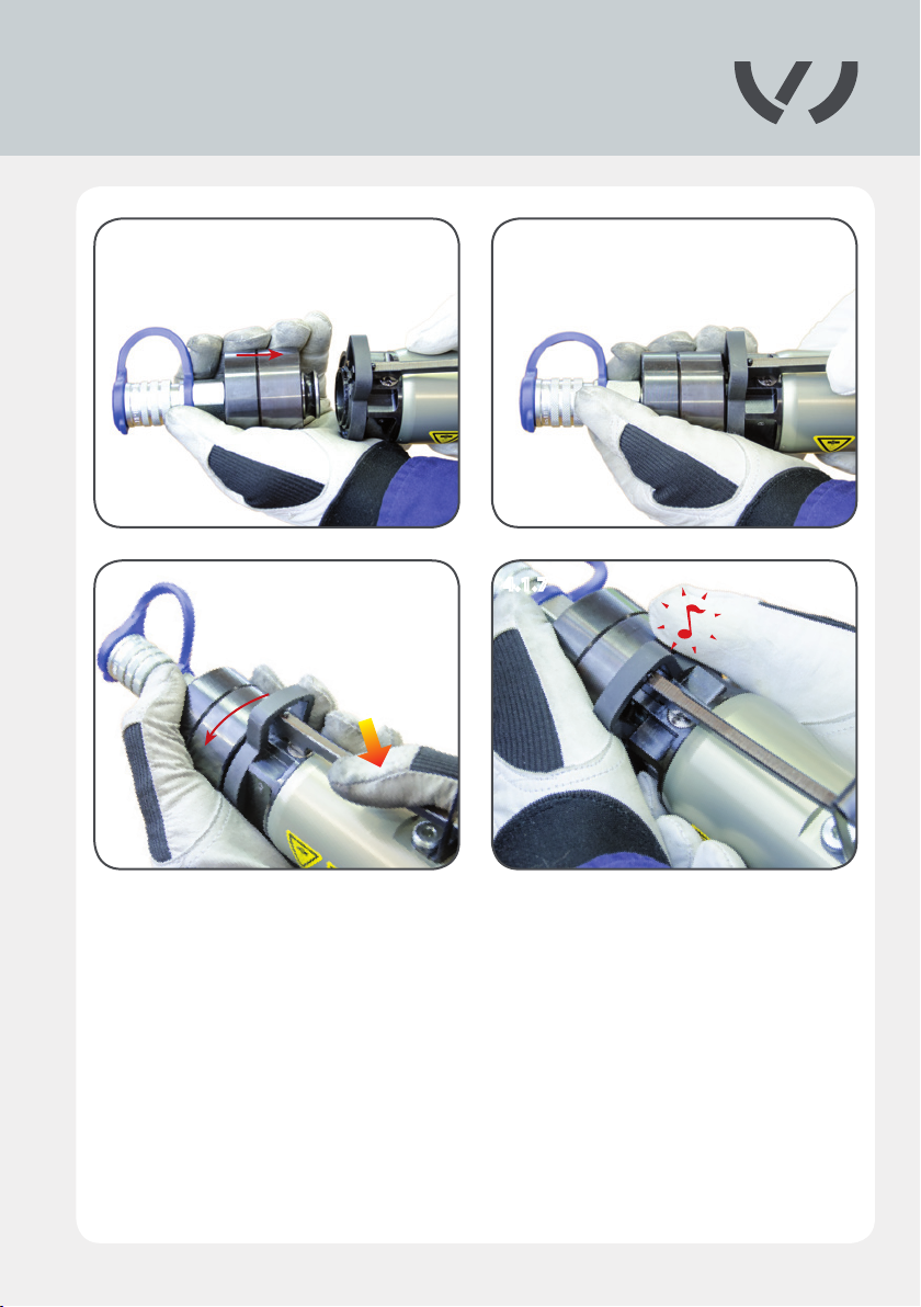
4.1.4 4.1.5
4.1.6 4.1.7
4.1.4 – 4.1.7
Insert the high-pressure coupling straight into the seating on the Compact Booster and turn
the locking mechanism counterclockwise until it engages.
19
Page 20
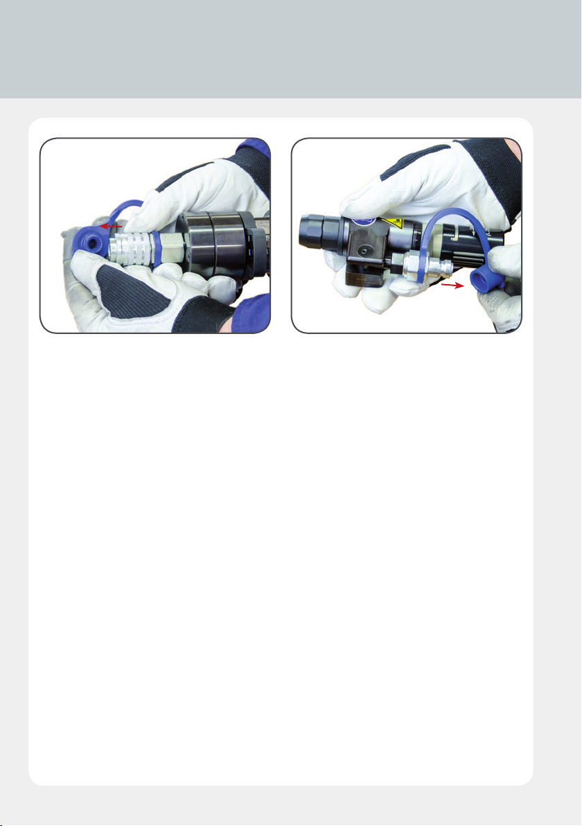
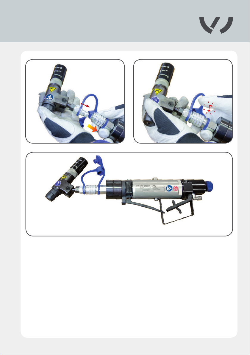
4.2 Connecting the blind riveting tool and the
Compact Booster
4.2.1 4.2.2
4.2.1/4.2.2
Remove the protective caps from the high-pressure coupling and the blind riveting tool.
20
Page 21
4.2.3 4.2.4
4.2.5
4.2.3 – 4.2.5
Use the high-pressure coupling to connect the blind riveting tool and the Compact Booster,
ensuring they engage audibly.
21
Page 22
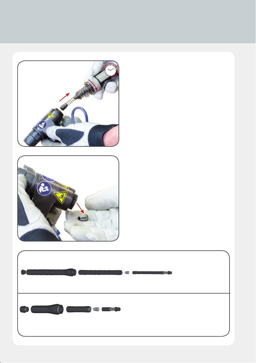
4.3 VAS 6792/2, VAS 6792/24: Screwing the extension
onto the blind riveting tool
4.3.1
4.3.2
4.3.1
Remove the mandrel collector from the blind
riveting tool.
4.3.2/4.3.3
Remove the conical grip from the blind rive-
ting tool. The extension is set up as shown in
Fig. 4.3.3.
4.3.3
VAS 6792/24
VAS 6792/2
22
Page 23
4.3.4 4.3.5
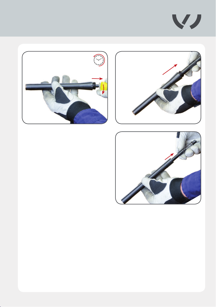
4.3.64.3.4 – 4.3.6
Unscrew the yellow protective cover from
the extension. Remove the extension sleeve
from the housing. Then remove the extensi-
on rod from the extension sleeve.
23
Page 24
4.3 VAS 6792/2, VAS 6792/24: Screwing the extension
onto the blind riveting tool
4.3.7
4.3.8
VAS 6792/2
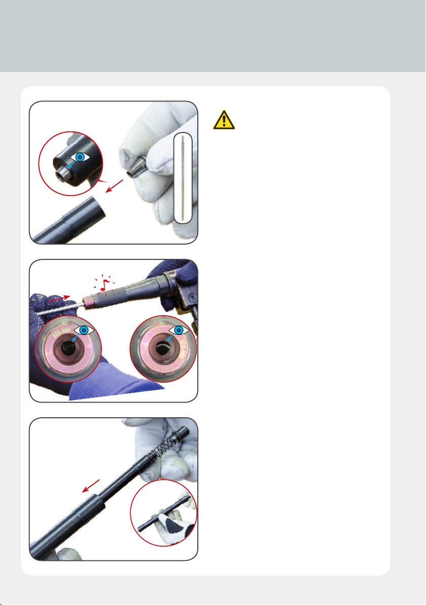
4.3.7/4.3.8
Insert the appropriate conical grip
into the extension rod.
Ensure that the conical side of the conical
grip is facing the extension rod.
Only for VAS6792/2: Before setting up, al-
ways position the conical grip in the tool
correctly, using the assembly aid.
73
4.3.9
24
4.3.9
Then relocate the extension rod back into the
extension sleeve.
Page 25
4.3.10 4.3.11
4.3.10/4.3.11
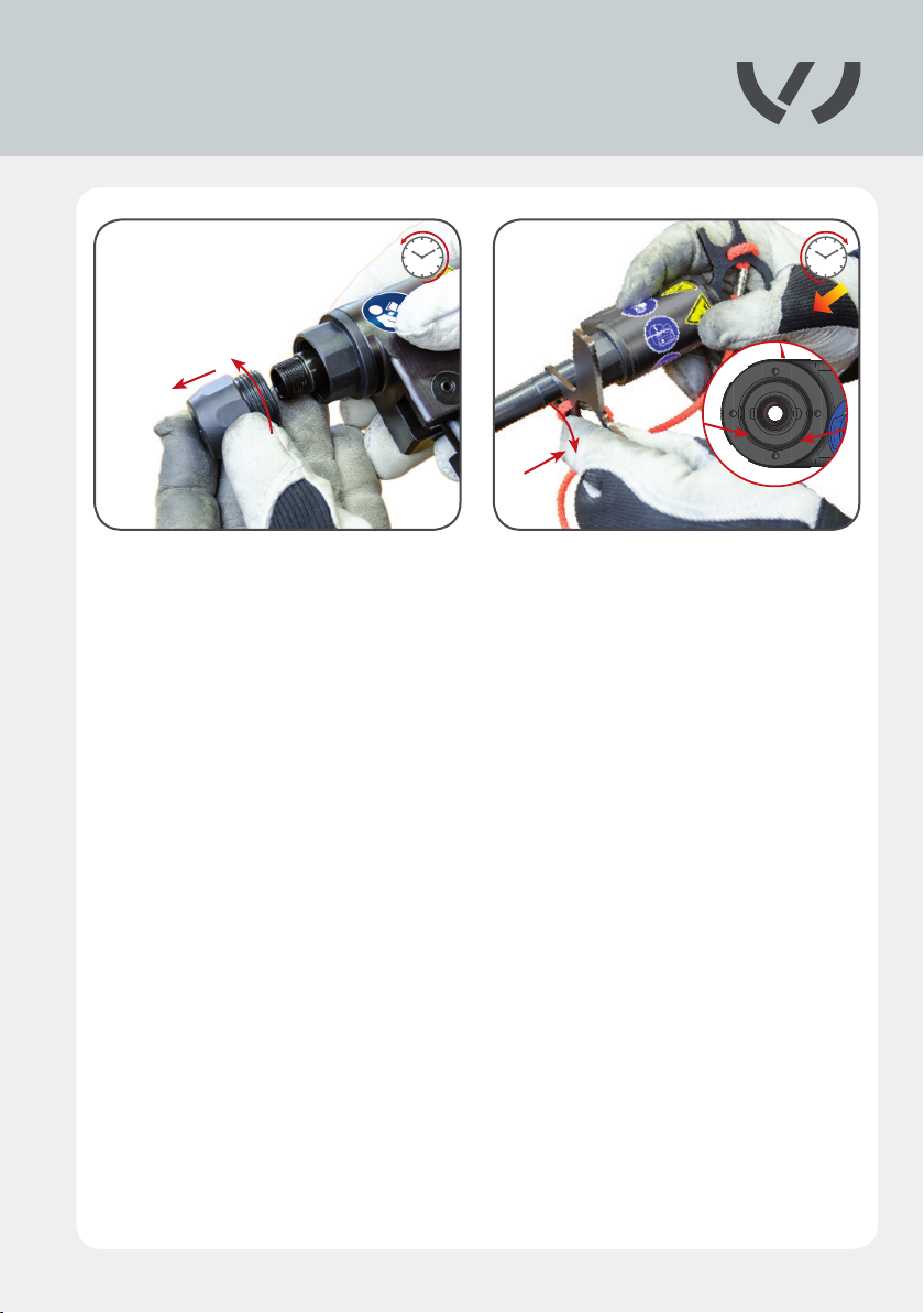
Remove the rivet head from the blind riveting tool before fully securing the extension sleeve
up to the stop with the assembly wrench. Take extra care over this, ensuring that the assembly
wrench is positioned in the notches provided in the blind riveting tool to allow the extension
sleeve to be detached.
25
Page 26
4.3 VAS 6792/2, VAS 6792/24: Screwing the extension
onto the blind riveting tool
4.3.12 4.3.13
4.3.12 – 4.3.14
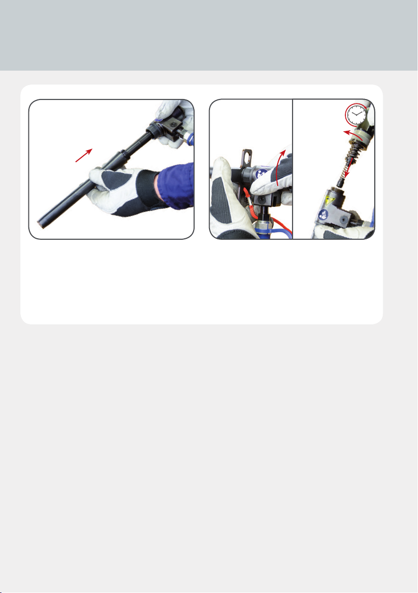
Fit the extension casing over the extension sleeve and secure it to the blind riveting tool.
Hand-tighten the casing with the assembly wrench. Then t the mandrel collector.
26
Page 27
4.4 Replacing the extension rivet head
4.4.1 4.4.2
4.4.1 – 4.4.2
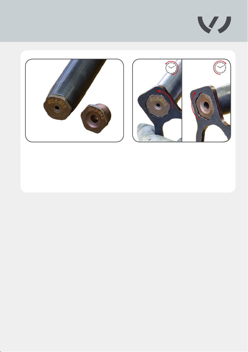
When changing the rivet head on the extension, note that it must be hand-tightened using
the assembly wrench.
27
Page 28
4.5 Removing the extension
4.5.1
4.5.2
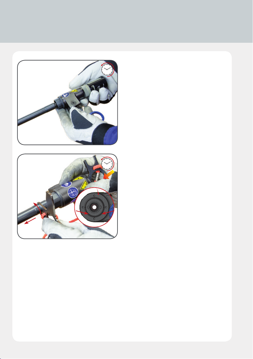
4.5.1
To remove the extension sleeve from the
blind riveting tool, the mandrel collector
must rst be removed.
4.5.2
Then t the assembly wrench to the blind
riveting tool at the back. Take particular care
to ensure that the assembly wrench is posi-
tioned in the notches provided in the blind
riveting tool to allow the extension sleeve to
be detached. Remove the conical grip from
the extension sleeve and replace it in the
blind riveting tool.
28
Page 29
4.6 Replacing the conical grip
4.6.1 4.6.2
4.6.1/4.6.2
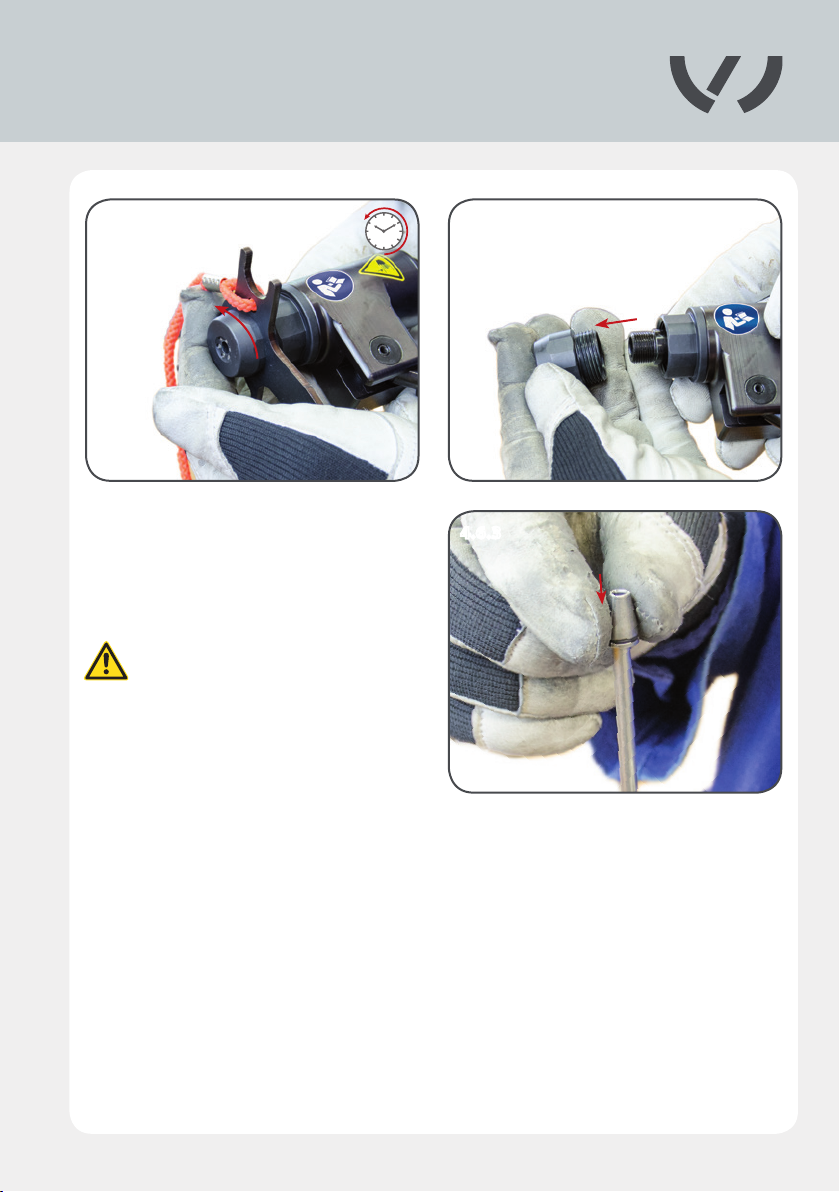
Unscrew the rivet head with the assembly
wrench and remove.
4.6.3
Position the conical grips at the
point of the assembly aid.
Ensure that the conical side faces
up.
4.6.3
29
Page 30
4.6 Replacing the conical grip
4.6.4 4.6.5
BA3
4.6.4/4.6.5
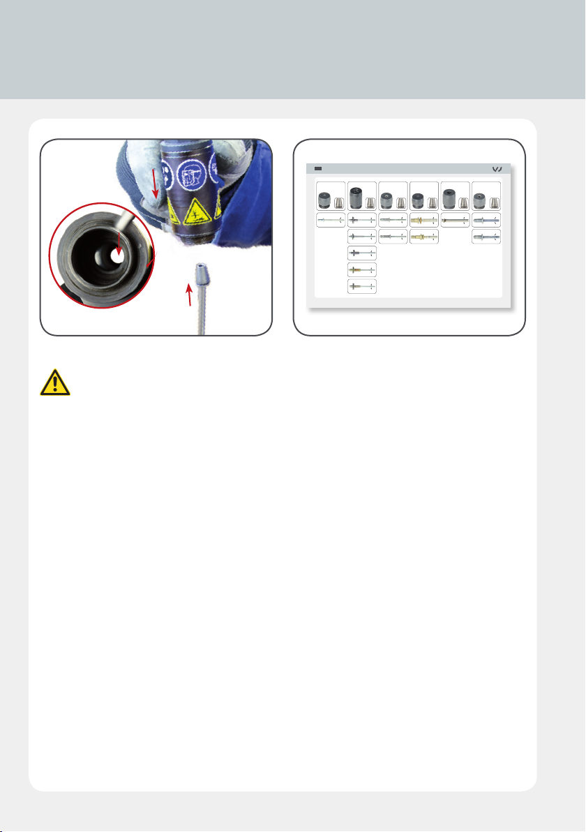
Insert the assembly aid into the opening in the blind riveting tool.
Select the right conical grip for the rivet head (see rivet matrix).
Nietmatrix
VAS 6792/11
Ø 2,0 mm
VAS 6792/15 VAS 6792/17 VAS 6792/19VAS 6792/16 VAS 6792/18 VAS 6792/20
Ø 2,0 mm Ø 2,6 mm Ø 3,0 mm
VAS 6792/13
VAS 6792/14
Ø 3,0 mm
Ø 2,6 mm
Ø 3,0 mm
Ø 2,6 mm
Ø 2,6 mm
Ø 2,6 mm
Ø 2,6 mm
VAS 6792/12
VAS 6792/10
Ø 4,0 mm
Ø 3,4 mm
Ø 3,4 mm
Ø 3,4 mm
VAS 6792/27
Ø 4,0 – 4,2 mm
Ø 4,0 mm Ø 4,0 – 4,2 mm
Ø 4,0 – 4,2 mm
PSD-BED-00000125, Vers. 14.12
30
Page 31
4.6.6 4.6.7
4.6.84.6.6 - 4.6.8
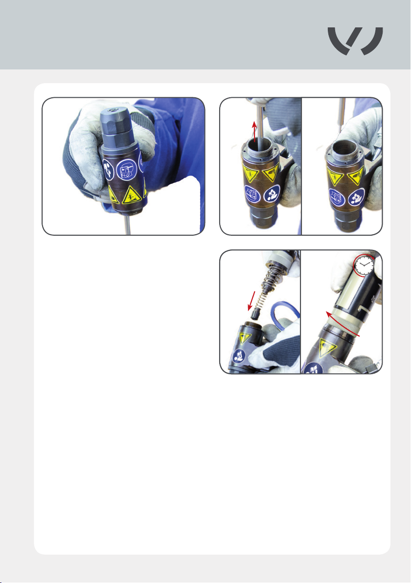
Once the conical grip has been inserted into
the blind riveting tool, the mandrel collector
must be tted.
31
Page 32

4.7 Connecting the spiral hose to the Compact
Booster and hose adapter
4.7.1 4.7.2
4.7.3 4.7.4
4.7.1/4.7.2
Connect the spiral hose to the Compact Booster.
4.7.3/4.7.4
Connect the plug on the hose to the hose adapter. The hose adapter can now be connected
up to the workshop‘s air supply.
32
Page 33
4.8 Connecting the pneumatic hose to the
Compact Booster and the spiral hose
4.8.1 4.8.2
4.8.3
4.8.1 – 4.8.3
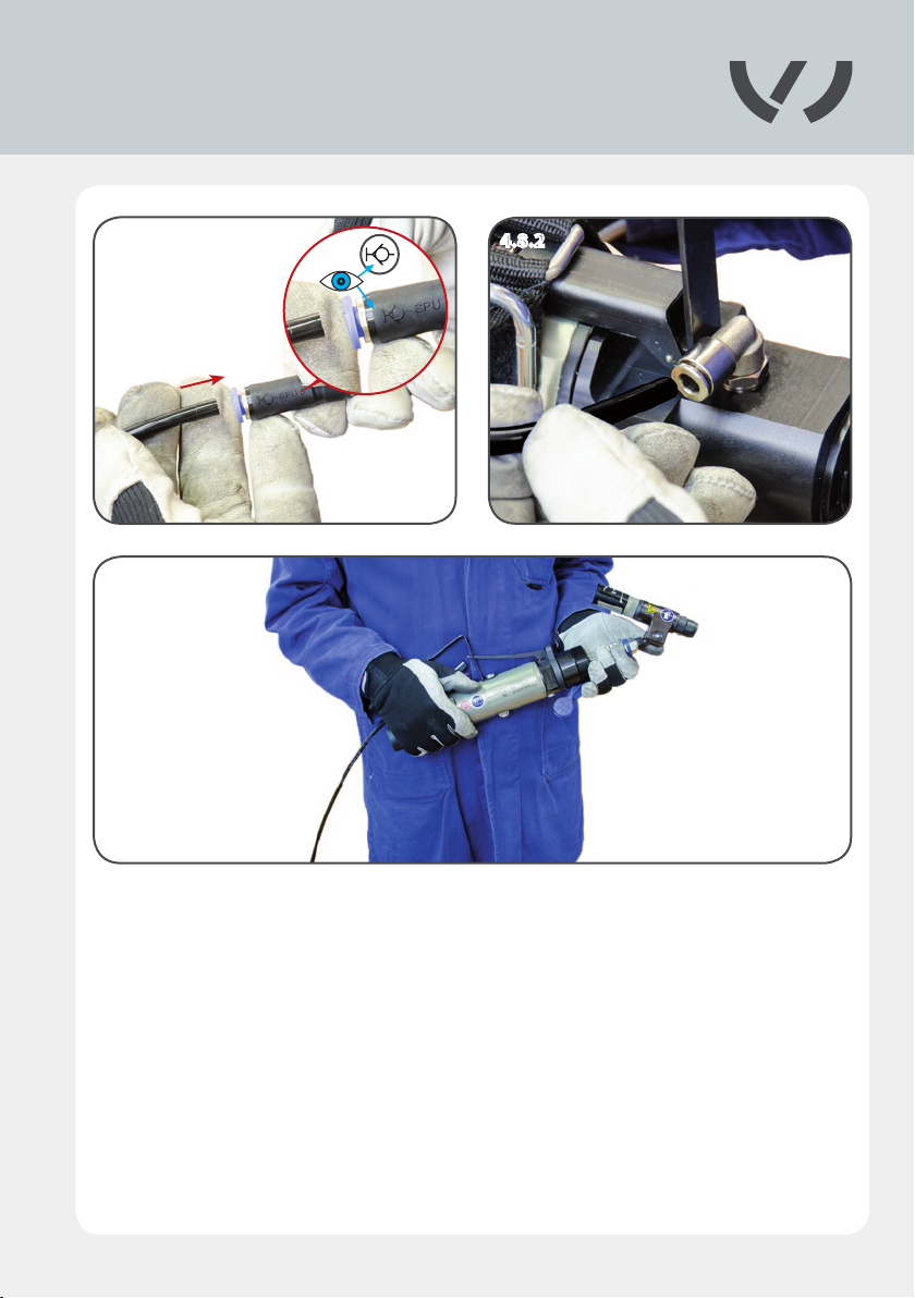
Connect the spiral hose with the hose adapter and the black pneumatic hose. Then secure the
pneumatic hose to the Compact Booster.
33
Page 34
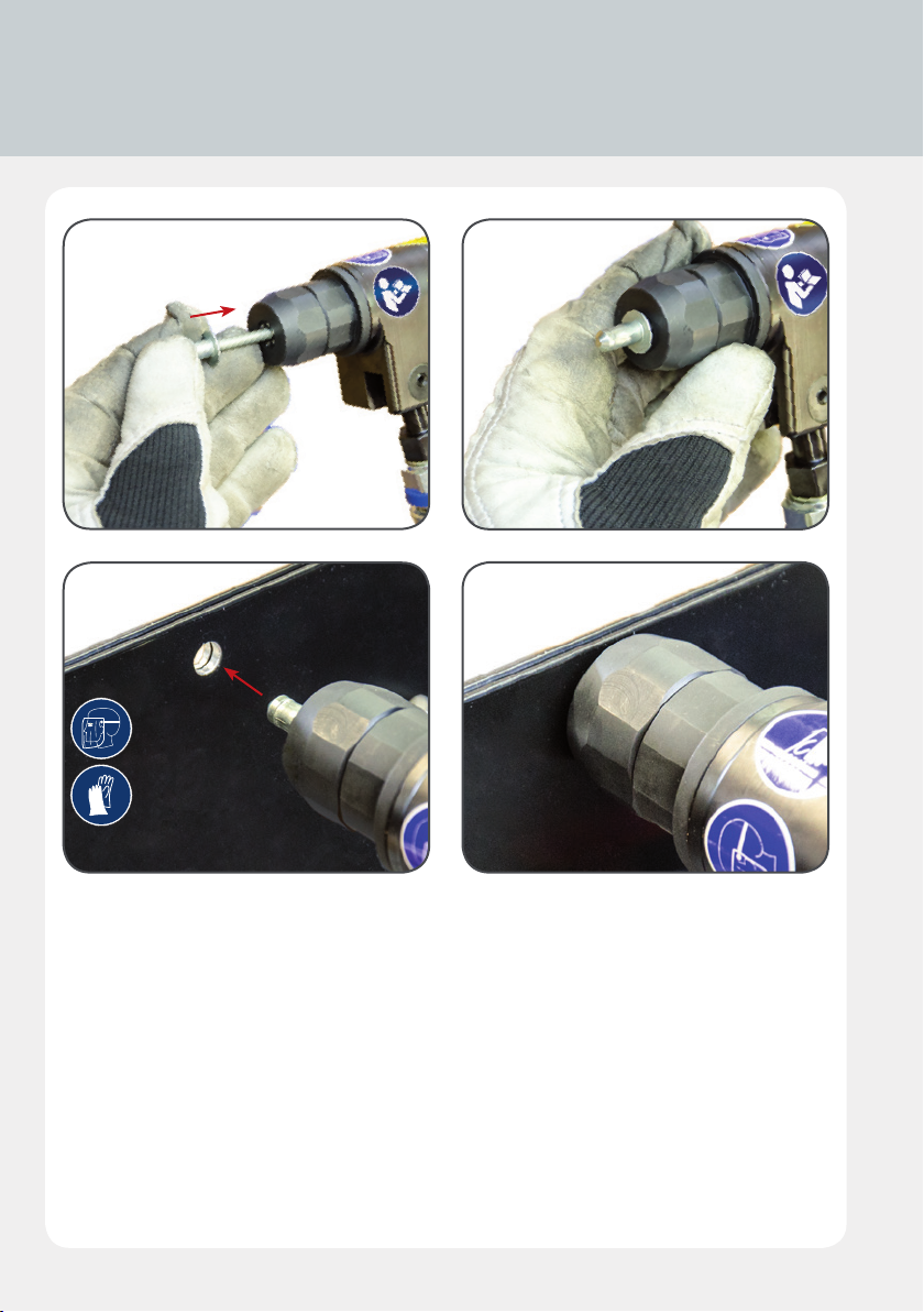
4.9 Using the blind riveting tool
4.9.1 4.9.2
4.9.3 4.9.4
4.9.1/4.9.2
Insert the blind rivet, centered in the tool's rivet guide.
4.9.3/4.9.4
Position the blind riveting tool and insert it into the hole provided as far as the contact surface.
34
Page 35
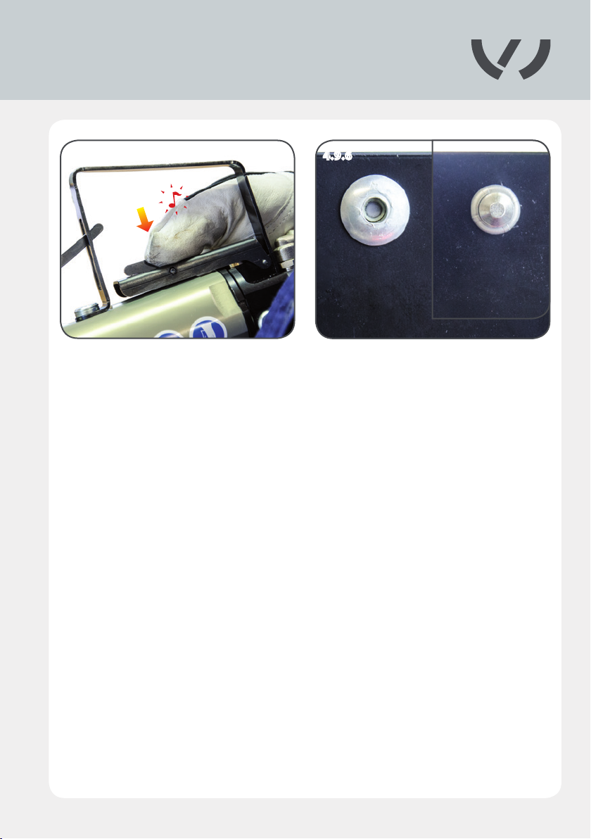
4.9.5 4.9.6
4.9.5/4.9.6
Start the riveting operation by pressing the lever on the Compact Booster. Draw the mandrel
into the tool. The projecting part of the mandrel breaks at the front side at the intended
breaking point. This causes the rivet material to spread out around the rivet head on the
opposite side.
35
Page 36
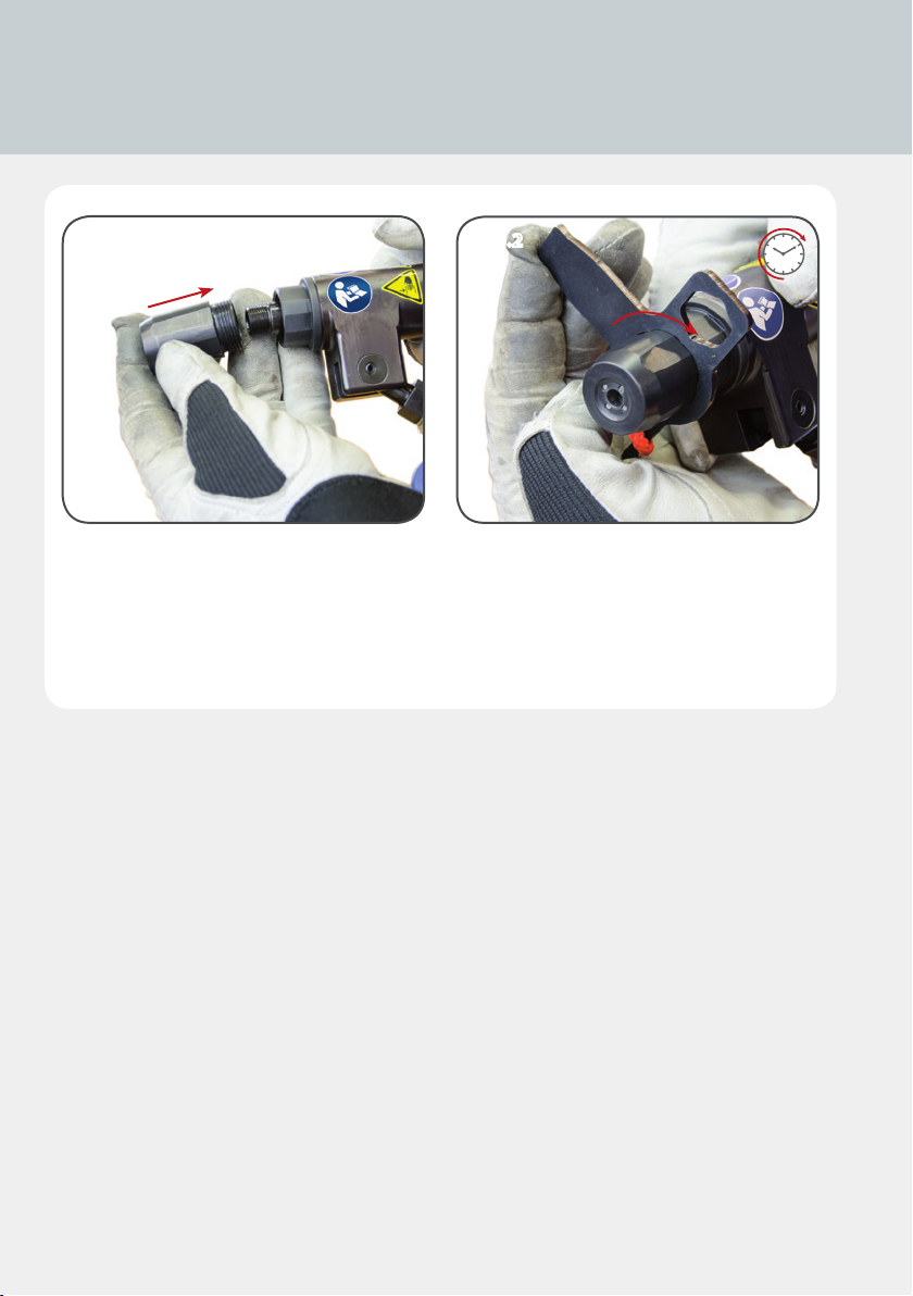
4.10 Replacing the rivet head
4.10.1 4.10.2
4.10.1/4.10.2
When changing the rivet head, the replacement rivet head must be hand-tightened with the
assembly wrench.
36
Page 37
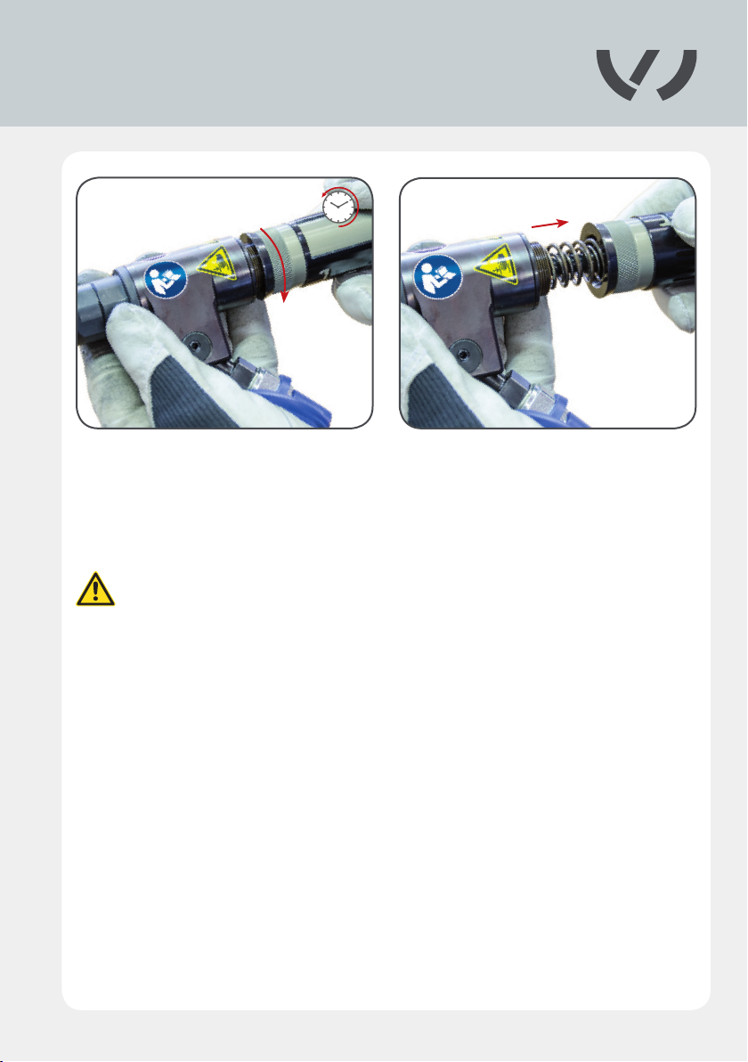
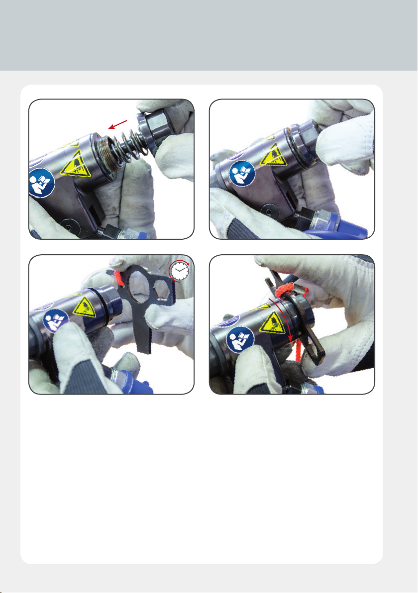
4.11 Fitting the front ejector
4.11.1 4.11.2
4.11.1/4.11.2
Turn the mandrel collector counterclockwise.
The compressed air supply MUST be switched off.
When opening the blind riveting tool, hold it angled slightly forward because
the conical grip can fall out.
37
Page 38
4.11 Fitting the front ejector
4.11.3 4.11.4
4.11.5 4.11.6
4.11.3/4.11.4
Insert the front ejector and tighten clockwise until the contact surface is reached.
4.11.5/4.11.6
Tighten by hand using the large opening of the assembly wrench.
When not in use, keep the front ejector in the protective cover provided for this purpose.
38
Page 39
4.12 Using with the operating unit
4.12.1 4.12.2
4.12.1 – 4.12.3
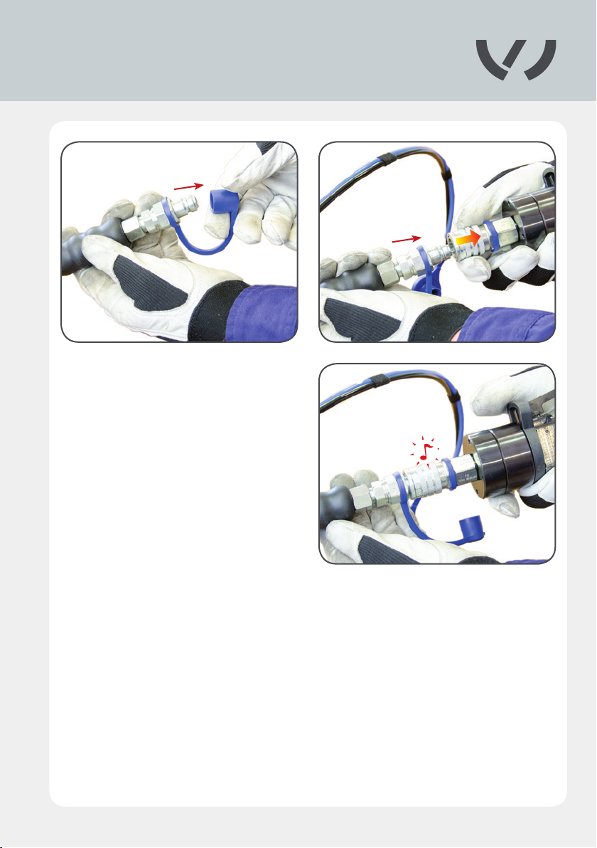
Remove the protective cap on the hose as-
sembly and connect the coupling to the
high-pressure coupling on the Compact
Booster.
4.12.3
39
Page 40
4.12 Using with the operating unit
4.12.4
4.12.5
4.12.4
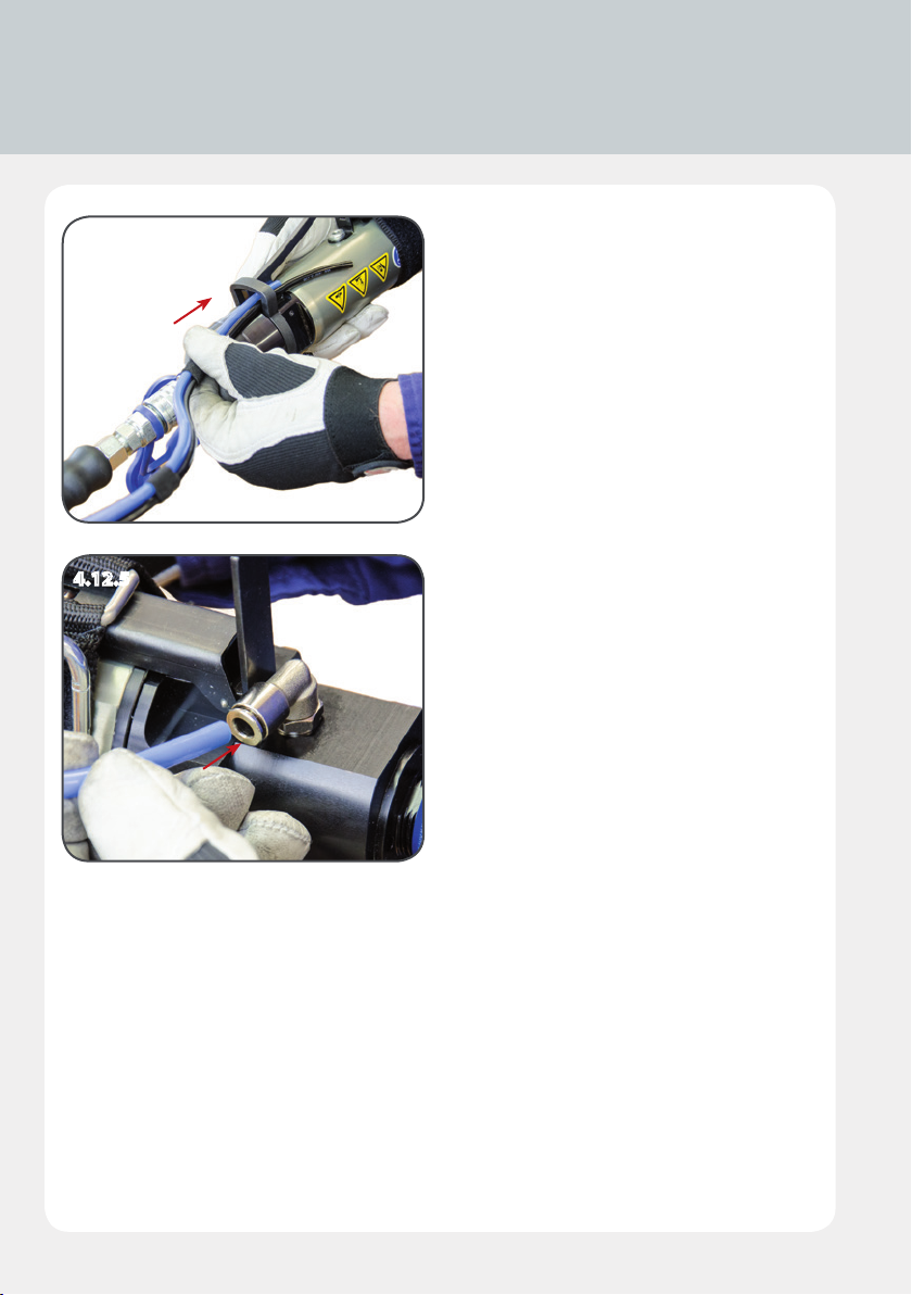
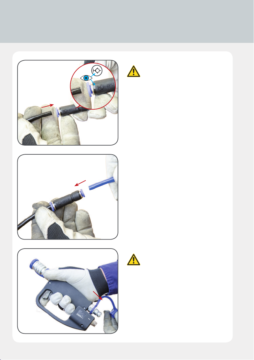
Lead the blue and black hoses through the
opening in the locking mechanism so they
are out of the way during use.
4.12.5
Connect the blue hose to the hose assembly
to the Compact Booster.
40
Page 41
4.12.6 4.12.7
4.12.84.12.6 – 4.12.8
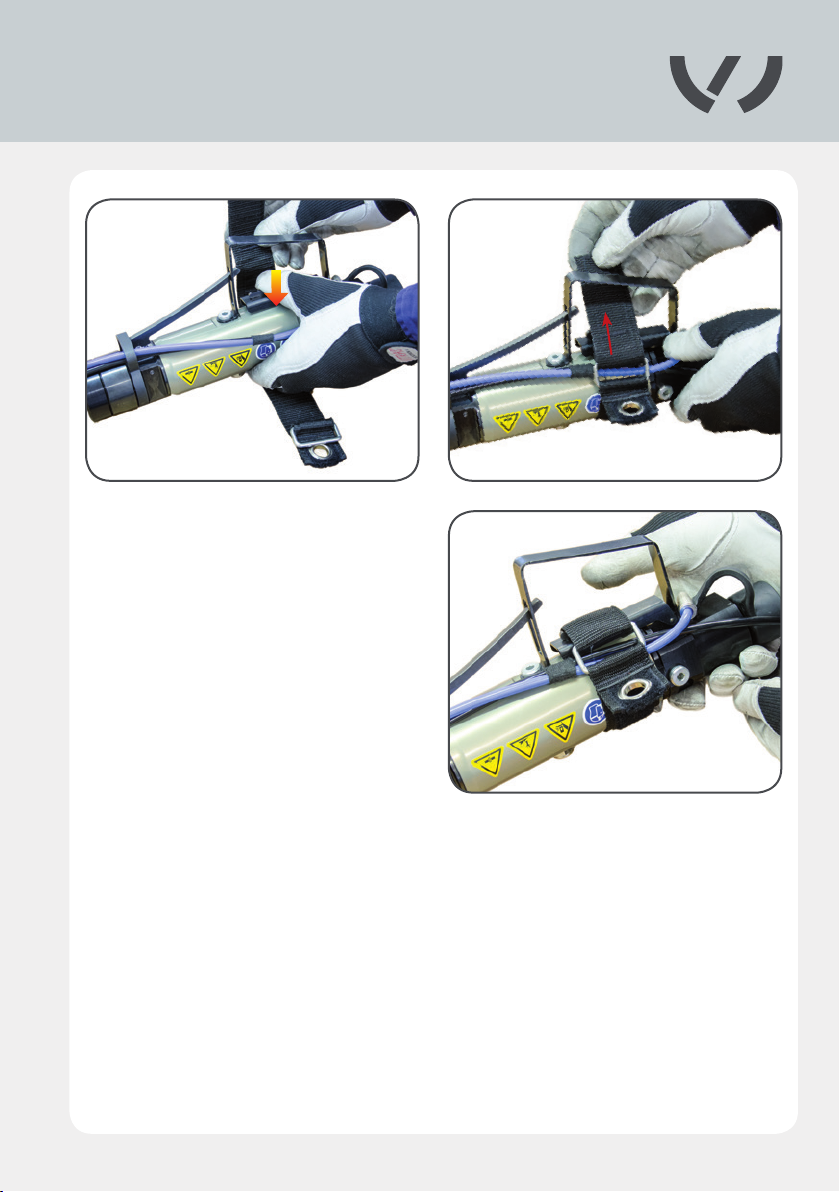
Secure the support belt around the depres-
sed lever on the Compact Booster because
rivet setting is controlled by the operating
unit.
41
Page 42
4.12 Using with the operating unit
4.12.9
4.12.10
4.12.9
Connect the black hose to the plug
connector.
Always ensure that the plug con-
nector symbol is pointing toward
the black hose.
4.12.10
Then connect the spiral hose to the other
side of the plug connector.
4.12.11
42
4.12.11
Remove the protective cap from
the pressure connection on the
operating unit.
Page 43
4.12.12 4.12.13
4.12.14 4.12.15
4.12.12 – 4.12.15
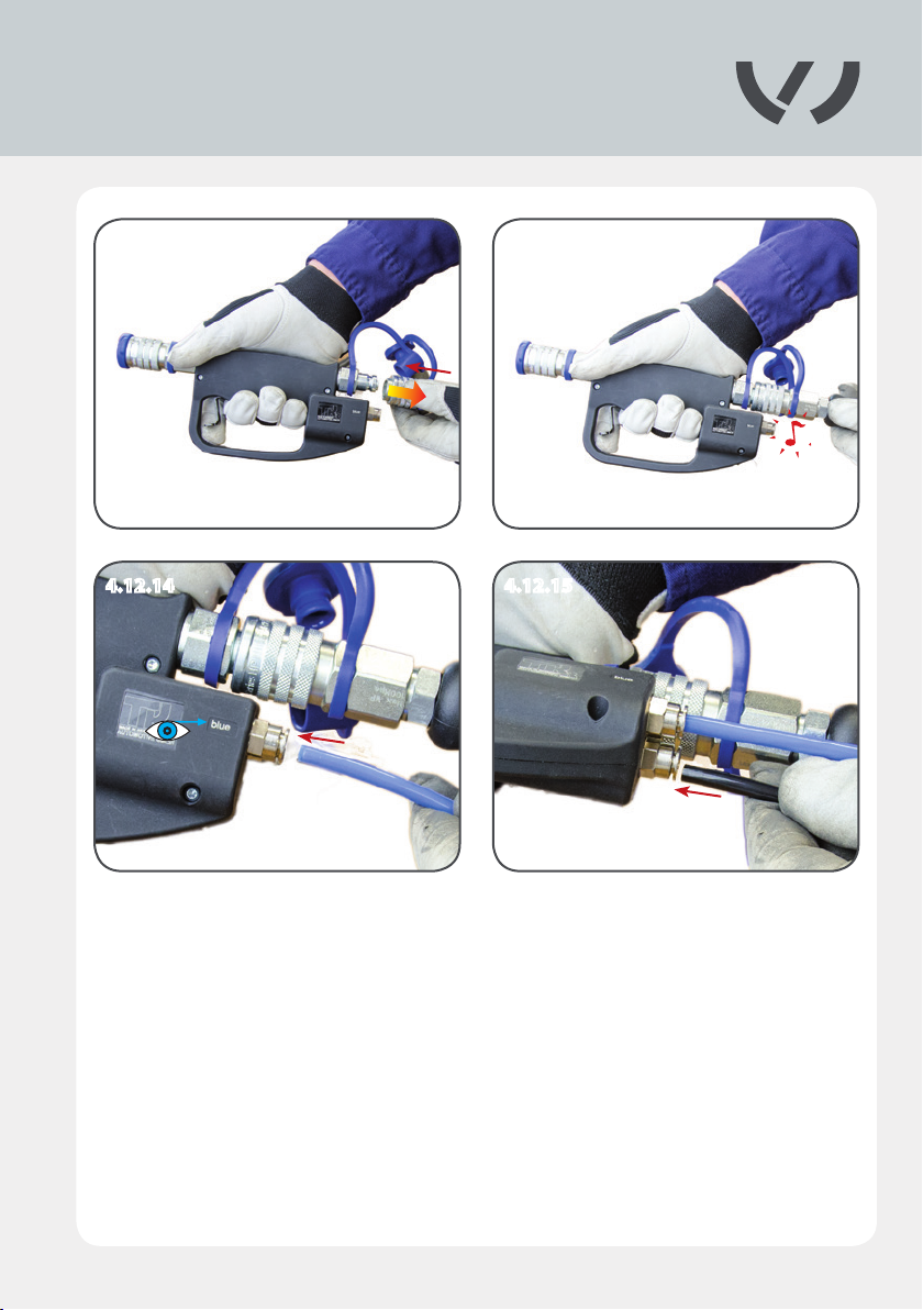
Now connect the hose assembly to the operating unit. Then connect the blue and black hoses
to the operating unit.
Note that the hoses must be inserted in accordance with the lettering.
43
Page 44
4.12 Using with the operating unit
4.12.16
4.12.17
4.12.16
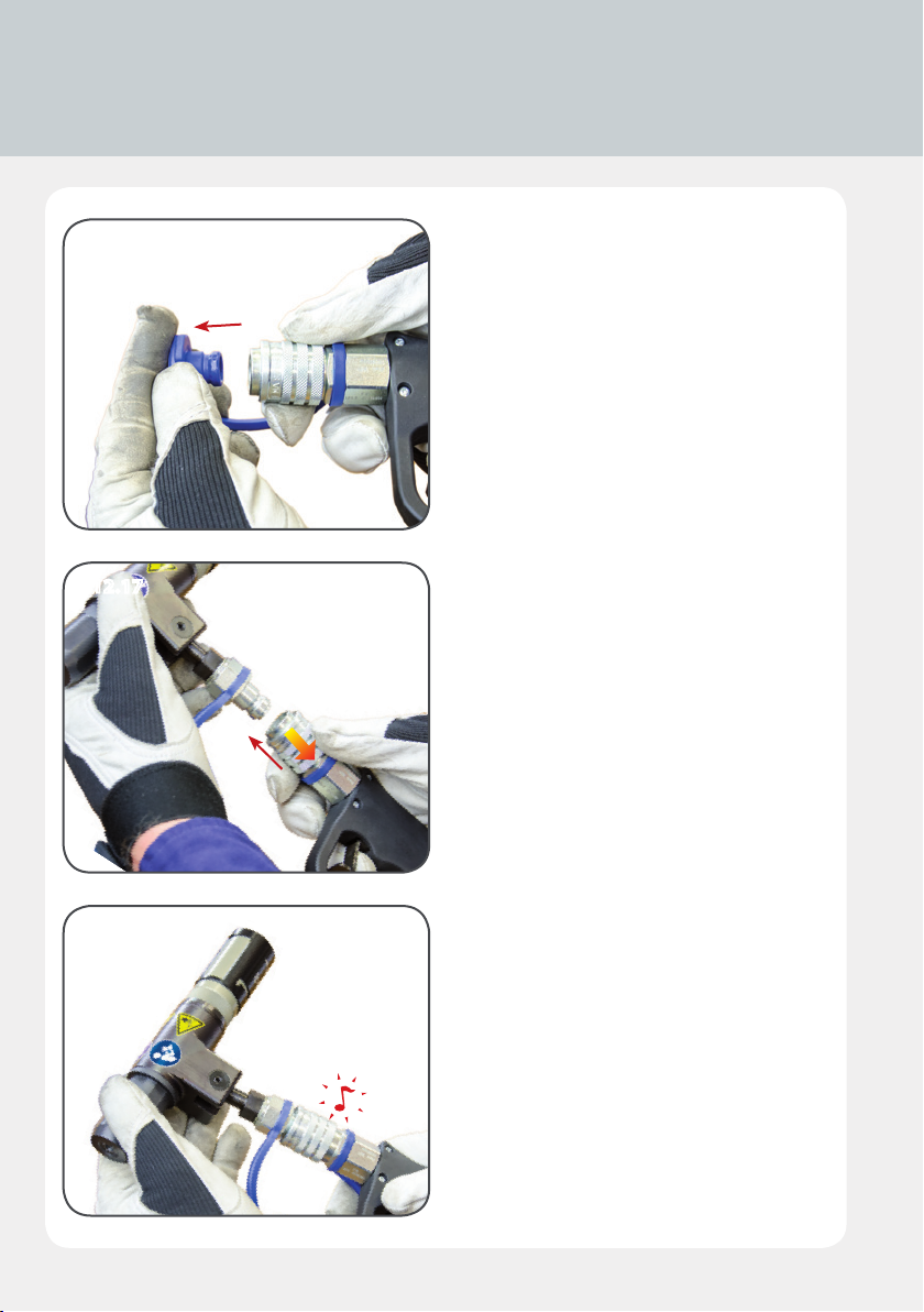
Remove the front protective cap on the ope-
rating unit and the protective cap on the
blind riveting tool.
4.12.17/4.12.18
The blind riveting tool can now be connected
to the operating unit.
4.12.18
44
Page 45
4.12.19
4.12.19
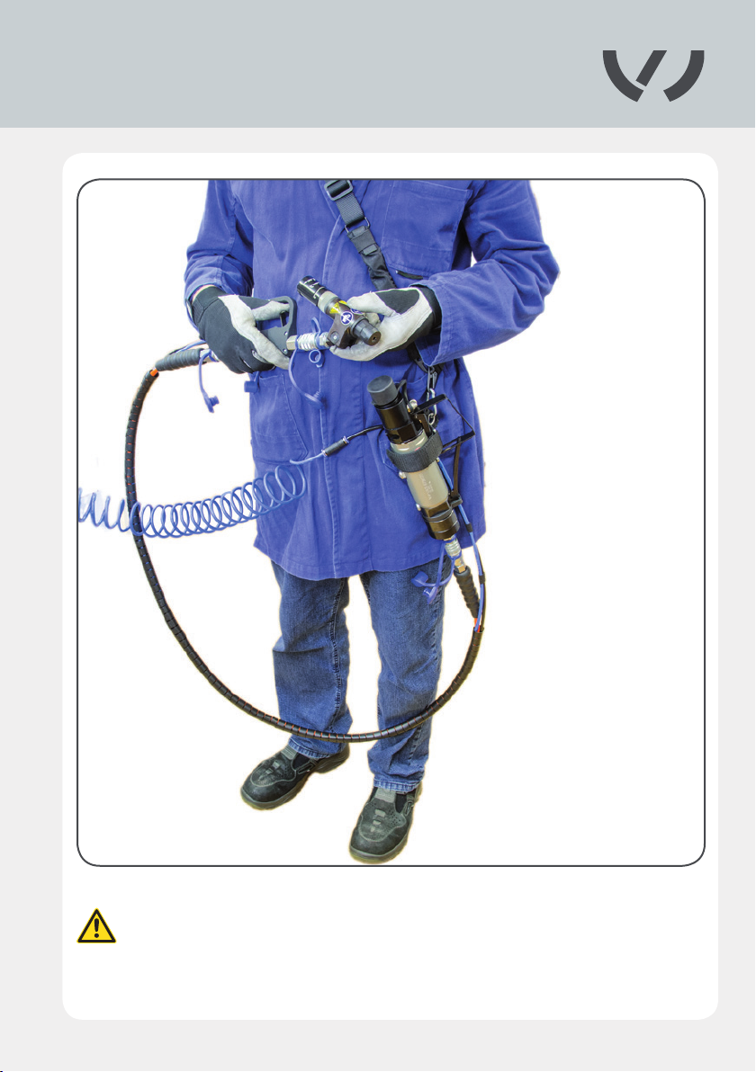
The blind riveting tool must be used as shown in the illustration, by a professi-
onal operator trained in its use.
45
Page 46
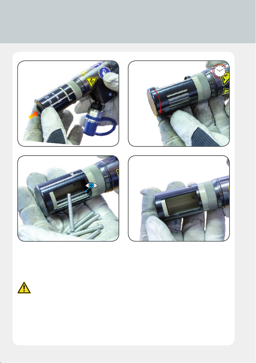
4.13 Emptying the mandrel collector
4.13.1 4.13.2
4.13.3 4.13.4
4.13.1
Press the mandrel collector towards the blind riveting tool, as shown in the laser engraving.
4.13.2 – 4.13.4
Turn the mandrel collector to open the recovery aperture to allow the mandrels to
be removed.
Empty the mandrel collector no more than 10 riveting operations. If there are
more than 10 mandrels in the collector, this can result in damage to the riveting
tool.
46
Page 47
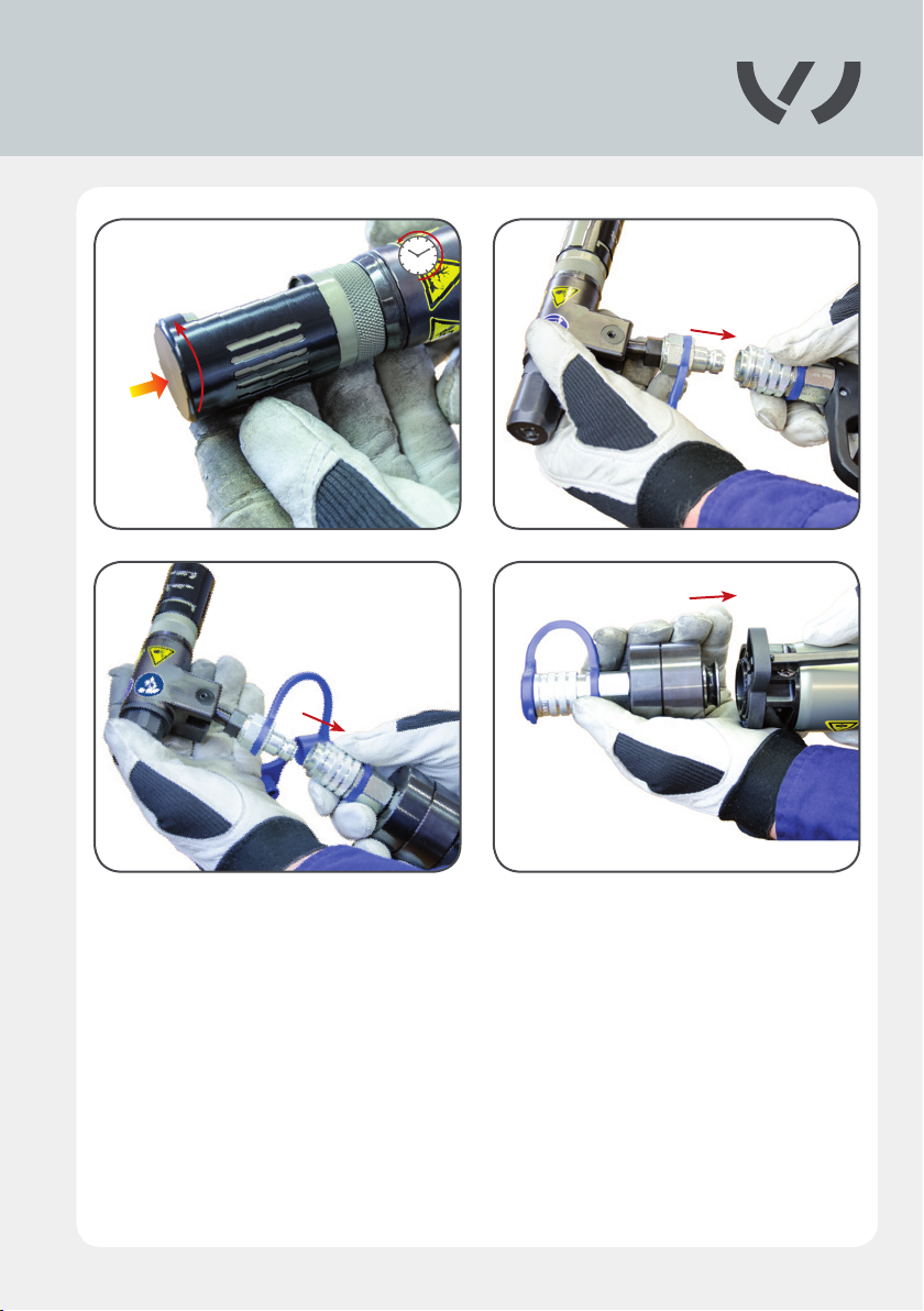
4.14 Maintenance and cleaning
4.13.5 4.14.1
4.14.2 4.14.3
4.13.5
To close, press the mandrel collector towards the riveting tool, as shown in the laser engraving.
Turn the mandrel collector to close the recovery aperture.
4.14.1 – 4.14.3
Disconnect the blind riveting tool from the operating unit and/or the high-pressure coupling.
Remove the high-pressure coupling from the Compact Booster.
47
Page 48
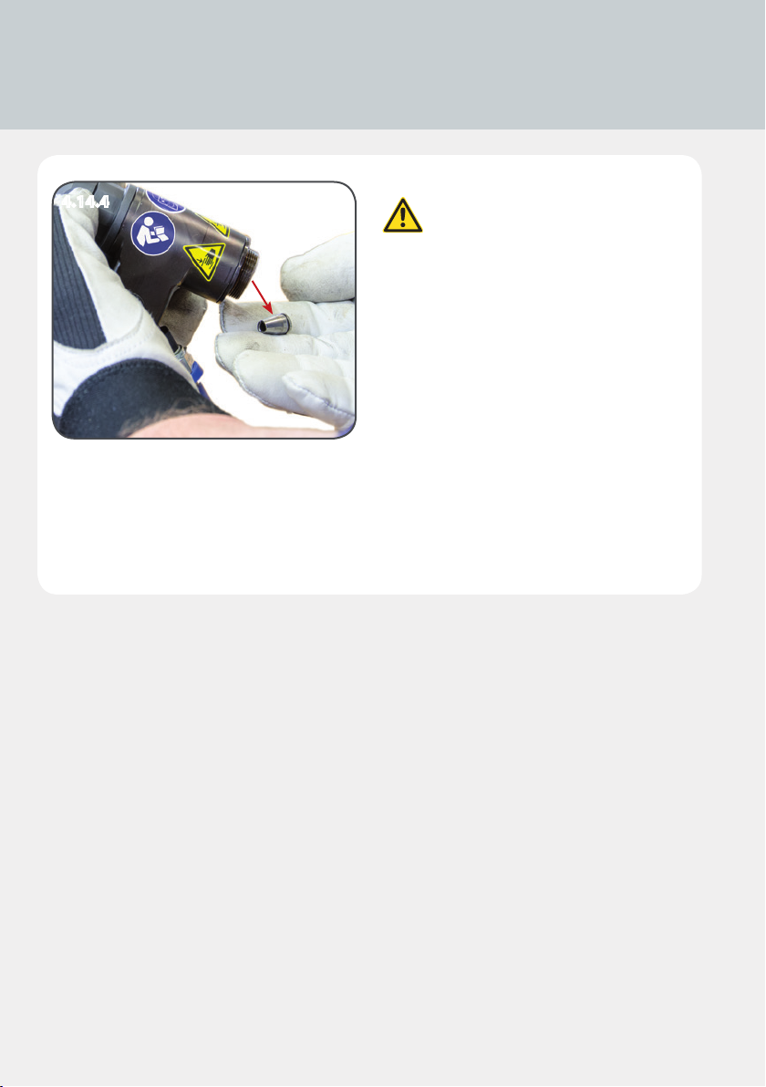
4.14 Maintenance and cleaning
4.14.4
4.14.4
Remove the conical grip from the
housing.
If a cone is left behind the piston
and the seal, both the tool and
cone will be damaged.
48
Page 49

Clean and check the gripper teeth on the conical grip. Replace the conical grip
if it is blunt.
Rounded teeth can cause faulty operation or damage to the tool.
Never use compressed air to clean the tool casing. This will result in dirt being blown into the
seals. Use a soft, lint-free cloth to clean the tool.
49
Page 50
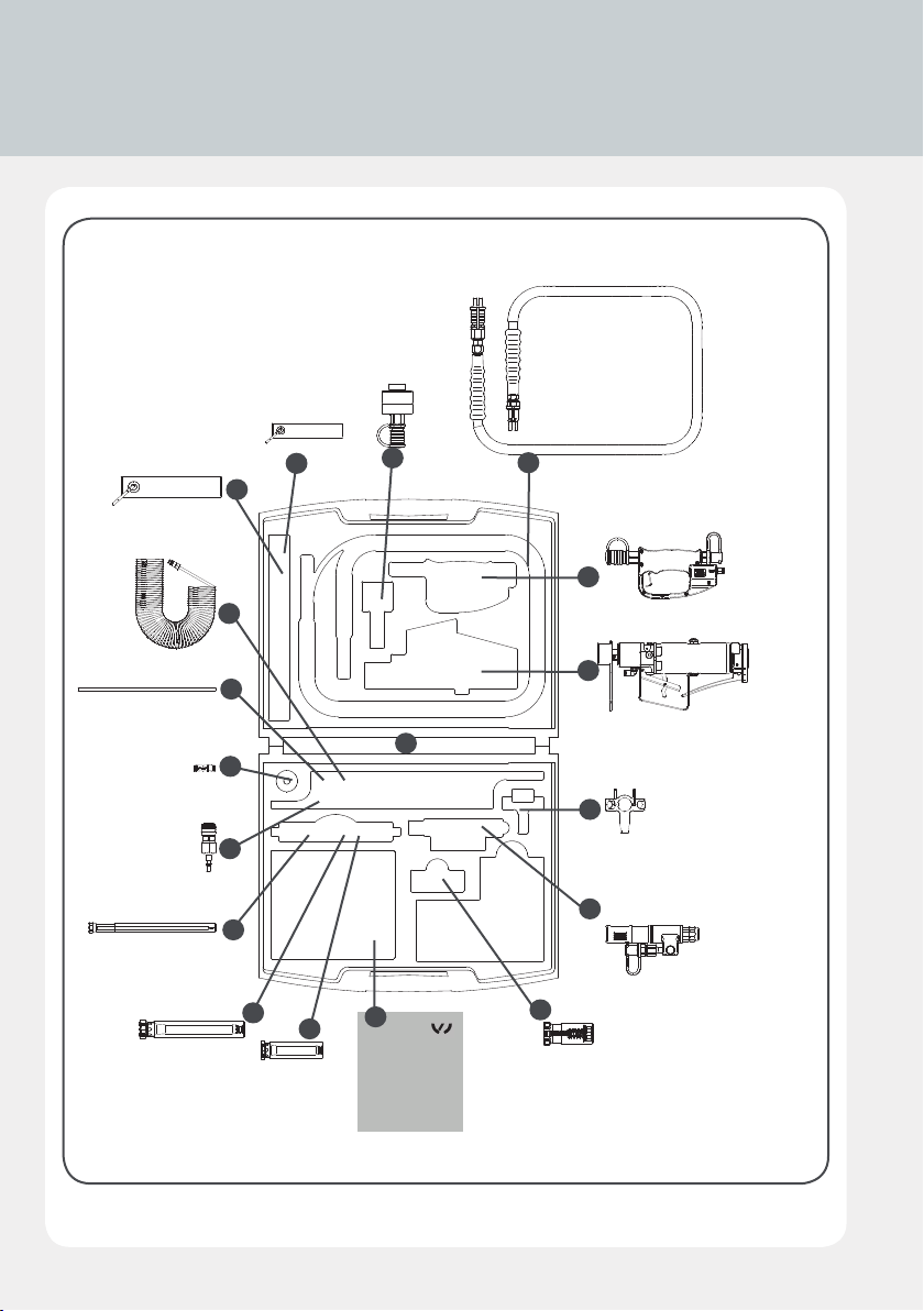
4.15 Spare parts
4.15.1
E1
G1
J1
K1
M1
B1
A1
O1
P1
C1
H1
Q1
D1
F1
I1
L1
N1
R1
50
Page 51
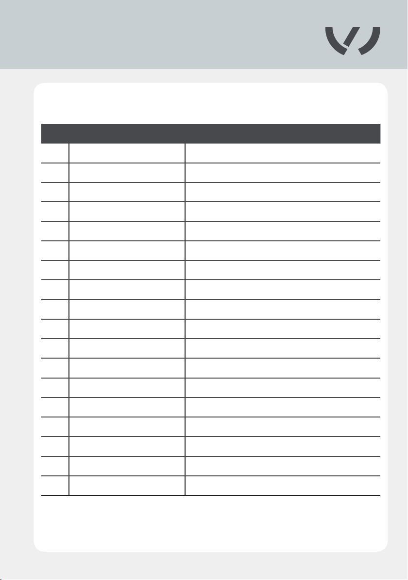
Overview
Artikelnr. Designation
A1 VAS 6790/56 Carrying strap
B1 VAS 6790/60 Supporting belt
C1 VAS 6792/7 High-pressure coupling
D1 VAS 6792/26 Hose package
E1 VAS 6790/55 Spiral hose
F1 VAS 6792/25 Operating unit
G1 VAS 6792/23 Pneumatic hose black Ø 6 mm
H1 VAS 6792/3 Blind riveting toolbox
I1 VAS 6790/20 Compact Booster
J1 VAS 6792/22 Plug connector
K1 VAS 6790/54 Compact Booster hose adapter
L1 VAS 6792/6 Assembly wrench
M1 VAS 6792/5 Assembly aid
N1 VAS 6792/4 Blind riveting tool
O1 VAS 6792/24 Extension 160 mm
P1 VAS 6792/2 Extension 59 mm
Q1 VAS 6790/50 Empty folder A5
R1 VAS 6792/21 Front ejector
51
Page 52
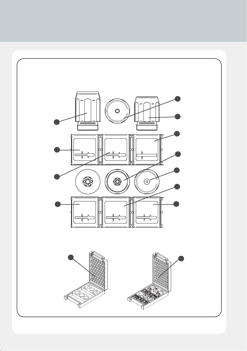
4.15 Spare parts
4.15.2
A2
E2
G2
,
3
4
Ø
VAS 6792/16
Ø 2,6 mm
–
0
,
4
Ø
J2
VAS 6792/20
Ø 4,0 – 4,2 mm
L2
VAS 6792/18
Ø 3,4 mm
Ø
4
,
2
Ø
–
6
,
2
Ø
VAS 6792/17
Ø 3,0 mm
VAS 6792/19
Ø 4,0 mm
2
3
,
0
Ø
VAS 6792/15
Ø 2,0 mm
B2
C2
D2
F2
H2
I2
K2
M2
52
Page 53
Overview
Artikelnr. Designation
A2 VAS 6792/14 Rivet holder for 2.6 mandrel
B2 VAS 6792/10 Rivet head for 3.4 mandrel
C2 VAS 6792/12 Rivet head for 4.0 mandrel
D2 VAS 6792/19 Conical grip, welding mandrel
E2 VAS 6792/16 Conical grip, 2.6 mandrel
F2 VAS 6792/13 Rivet holder for 3.0 mandrel
G2 VAS 6792/18 Conical grip, 3.4 mandrel
H2 VAS 6792/11 Rivet head for 2.0 mandrel
I2 VAS 6792/17 Conical grip, 3.0 mandrel
J2 VAS 6792/20 Conical grip, 4.2 mandrel
K2 VAS 6792/15 Conical grip, 2.0 mandrel
L2 VAS 6792/8 Blind rivet set box
M2 VAS 6792/9 Blind rivet set
53
Page 54

4.16 Troubleshooting
Problem Cause Remedy Chapter
Compressed air supply not connected
Control lines (black and blue hoses) incorrectly
connected
Control lines (black and blue hoses) not connected
Blind riveting tool not working
Insucient air pressure Check air supply at pressure intensier see BA1
Hydraulic hose assembly not coupled Connect hydraulic hose assembly in accordance with Operating Instructions 4.7,4.8
Compact Booster defective Arrange for repair by manufacturer/service partner
Control lines (black and blue hoses) incorrectly
connected
Control lines (black and blue hoses) not connected
Blind riveting tool cannot be switched o
Control valve defective (operating unit) Arrange for repair by manufacturer/service partner 2.5
Compact Booster defective Arrange for repair by manufacturer/service partner
Air leak Control valve defective (operating unit) Arrange for repair by manufacturer/service partner 2.5
54
Page 55

Connect compressed air
see BA1
Connect control lines (black and blue hoses) correctly, ensuring they are
properly seated.
Connect control lines (black and blue hoses) correctly, ensuring they are
properly seated.
Connect control lines (black and blue hoses) correctly, ensuring they are
properly seated.
Connect control lines (black and blue hoses) correctly, ensuring they are
properly seated.
4.12
4.12
see BA1
4.12
4.12
see BA1
55
Page 56

4.16 Troubleshooting
Problem Cause Remedy Chapter
Conical grips dirty
Blind rivet not being gripped, conical
grips slipping on mandrel
Blind riveting process not completed,
rivet shaft is not separated from rivet head
Oil leak
Gripper teeth on conical grips worn Replace worn conical grips with new 4.6
Incorrect conical grips Check and replace conical grips 4.6
Insucient quantity of oil (pressure intensier)
Gripper teeth on conical grips worn Replace worn conical grips with new. 4.6
Compact Booster defective Arrange for repair by manufacturer/service partner
Insucient air pressure Check air supply at pressure intensier see BA1
Hydraulic hose assembly defective
High-pressure coupling defective Arrange for repair by manufacturer/service partner 2.5
Blind riveting tool losing oil Arrange for repair by manufacturer/service partner 2.5
Screwing spring assembly/ejector into
housing requires application of excessive
force
56
Piston not in starting position - quantity of oil present
in housing
Defective thread Check thread and replace ejector, if necessary.
Page 57

Carefully clean conical grips 4.6
Check oil level and ll if necessary
see BA1
see BA1
Replace hydraulic hose assembly 2.5
Allow residual oil pressure to disperse by connecting the hydraulic hose and the
high-pressure push-t nipple (wait 10-20 seconds).
4.12
4.11
57
Page 58

4.16 Troubleshooting
Problem Cause Remedy Chapter
Conical grips in piston adapter (3-part) sitting in
dierent positions
Blind rivet cannot be inserted
Mandrel collector overlled - broken o mandrels can
no longer be carried back
Incorrect conical grips Check and replace conical grips
58
Page 59

Unscrew rivet guide and gently push conical grips back 2-5 mm with a blunt
implement until they are evenly positioned.
4.6
Empty the collector. Use a blunt implement to push back any mandrels left in
the casing.
4.13
4.6
59
Page 60

5.1 Disposal
Tools and machinery and components of idem and machinery must be dispo-
sed of in accordance with the laws, regulations and other stipulations of the
country in which they are located.
We recommend that disposal be undertaken by licensed professional operators.
Hydraulic oils and lubricants can be dangerous because they can contamina-
te groundwater. Used oil must not be mixed with other waste materials and
dierent types of used oil must not be mixed. Pay particular attention to the
terms of the German Environmental Liability Act and the Used Oil Directive,
including the stipulations they contain in regard to criminal acts and breaches
of regulations.
The manufacturer does not collected used hydraulic oils and lubricants free of
charge.
60
Page 61

5.2 Warranty
There is a warranty period of 24 on all TKR Spezialwerkzeuge GmbH stamping and riveting
tools that covers manufacturing or material defects. Otherwise, the statutory conditions go-
verning warranty periods and our General Terms and Conditions of Sale and Supply apply.
This does not cover those parts subject to wear and tear (rivet mandrels, rivet dies, screw
needles, extension) or hydraulic oil.
The warranty period begins on the date of delivery, as specied on the invoice or delivery
note.
The warranty is valid for the user/customer provided that the tool is purchased from an au-
thorised sales outlet and is used as described in the instructions and for the purposes for
which it was designed.
The warranty becomes invalid if the tool is used for purposes other than those for which it
was designed.
In addition, the warranty becomes invalid if the tool is not used as described in the instruc-
tion manual.
In the event of defect or fault, TKR Spezialwerkzeuge GmbH will only repair or replace faulty
parts at its own discretion.
Service department
TKR Spezialwerkzeuge GmbH
Service
Am Waldesrand 9-11
D-58285 Gevelsberg (Germany)
Phone: +49 23 32 666 07 - 0
Fax: +49 2332 666 07 - 941
E-Mail: [email protected]
Download-Service
www.tkr-support.com
61
Page 62

EU Declaration of Conformity
In accordance with EU Machinery Directive
2006/42/EC
Manufacturer: TKR Spezialwerkzeuge GmbH
Am Waldesrand 9-11
58285 Gevelsberg, Germany
Person authorised to
compile the technical
documentation: Thorsten Weyland
Tool type: Pneumatic/hydraulic stamping and riveting tool
Model designation: CB 1.0
Developed and manufactured in
accordance with the standards and
guidelines listed below by
TKR Spezialwerkzeuge GmbH
Am Waldesrand 9-11
58285 Gevelsberg (Germany)
Applied Product Safety Law (ProdSG)
harmonised EN 693; EN 11148-1; EN 11148-10; EN 792-13;
standards: EN ISO 4413; EN ISO 4414; ISO 11200;
ISO 11202; EN ISO 12100
Serial number range: 00001–10000
EU Machine Directive: 2006/42/EC
As manufacturer,
we declare that The products marked accordingly
comply with the requirements of the referenced
guidelines and standards.
Gevelsberg, 21.11.2014 Thorsten Weyland
Director of Development
62
Page 63

Page 64

Am Waldesrand 9–11
D-58285 Gevelsberg (Germany)
Phone: +492332 666 07 - 0
Fax: +492332 666 07 - 941
E-mail: [email protected]
Web: www.tkrgroup.com
PSD-BED-00000158, Rev4 19.01
 Loading...