

TKR Group PNP 90 UN 2.0 Instruction Manual
Pneumatic, hydraulic
Universal Riveting Tool
PNP 90 UN 2.0
Instruction manual

1.
2.
3.
4.
1. Information regarding this manual 3
2. Explanation of symbols 3
3. Designations 4
1. Operating principles 4
2. Scope of Supply and Accessories 5
3. Safety instructions 6
4. Principles for Handling the Tool Kit PNP 90 UN 2.0 7
5. Maintenance 8
6. Warranty 9
1. Technical Data Pump PNP 90 UN 2.0 10
2. Technical Data Hydraulic Actuator HP 35 UN 10
3. Technical Data Riveting Tool Kit RIVKIT UN 2.0 11
4. Technical Data Rivet Clamp 12
1. Startup 14
2. Riveting Tool Preparation and Connection of the Hydraulic Actuator 15
3. Safe Set-Up and Positioning of Equipment 17
4. Connecting the Tool to the Hydraulic Actuator 18
5. Riveting Tool Kit RIVKIT UN 2.0 – Fitting and Intended Use 19
5.
6.
1. Pressing out Rivets 20
2. Punching and Calibration of Holes for Flow Form Rivets 21
3. Setting of Flow Form Rivets 22
4. Installation of Semi-Tubular Punch Rivets 23
5 Checking Riveting Results 24
6. Cleaning the Riveting Tools 24
7. Completing an Operation and Riveting Tool Storage 25
1. Hydraulic pump maintenance 26
2. Replacement Part List 28
3. Troubleshooting 30
4. Declaration of Conformity 31
Accessories and spare parts:
www.tkr-powertools.com
2
1.1 Information regarding this manual
Information
Legislation stipulates that workers handling hydraulicallydriven riveting tools must be protected. If desired, training can be provided at TKR in Gevelsberg or on site at
the customer.
State of the technology
This riveting tool represents state-of-the-art technology.
To ensure the functionality of the equipment, it must be
operated in a proper and safe manner.
Read instruction manual
Read the instruction manual carefully before using the
riveting tool.
Handling
All handling necessary to ensure correct operation is
described in the instruction manual. No work method
other than that expressly approved by the manufacturer
may be used.
Faults
In the event of a fault, the user or owner may only carry
out repair work for faults for which the relevant maintenance
process is laid out in the instruction manual.
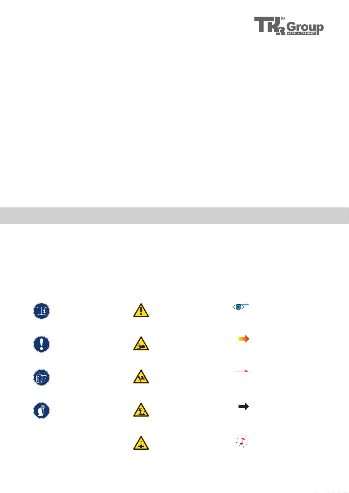
1.2 Explanation of symbols
In this instruction manual, some sections use internationally recognised warning symbols, warning
notes and general instructional symbols.
The individual symbols are explained below. Follow all instructions and safety rules.
Observe
Instruction manual
Observe
General instructions
Wear face mask
Wear gloves
Warning!
General source of danger
Warning!
Hand could become
trapped
Warning!
Fingers could become
trapped
Warning!
Danger of environmental
contamination
Please note the
following!
Arrow to clarify compression
Arrow showing direction
For further information
see chapter...
Warning!
System under pressure
Audibly engage
3
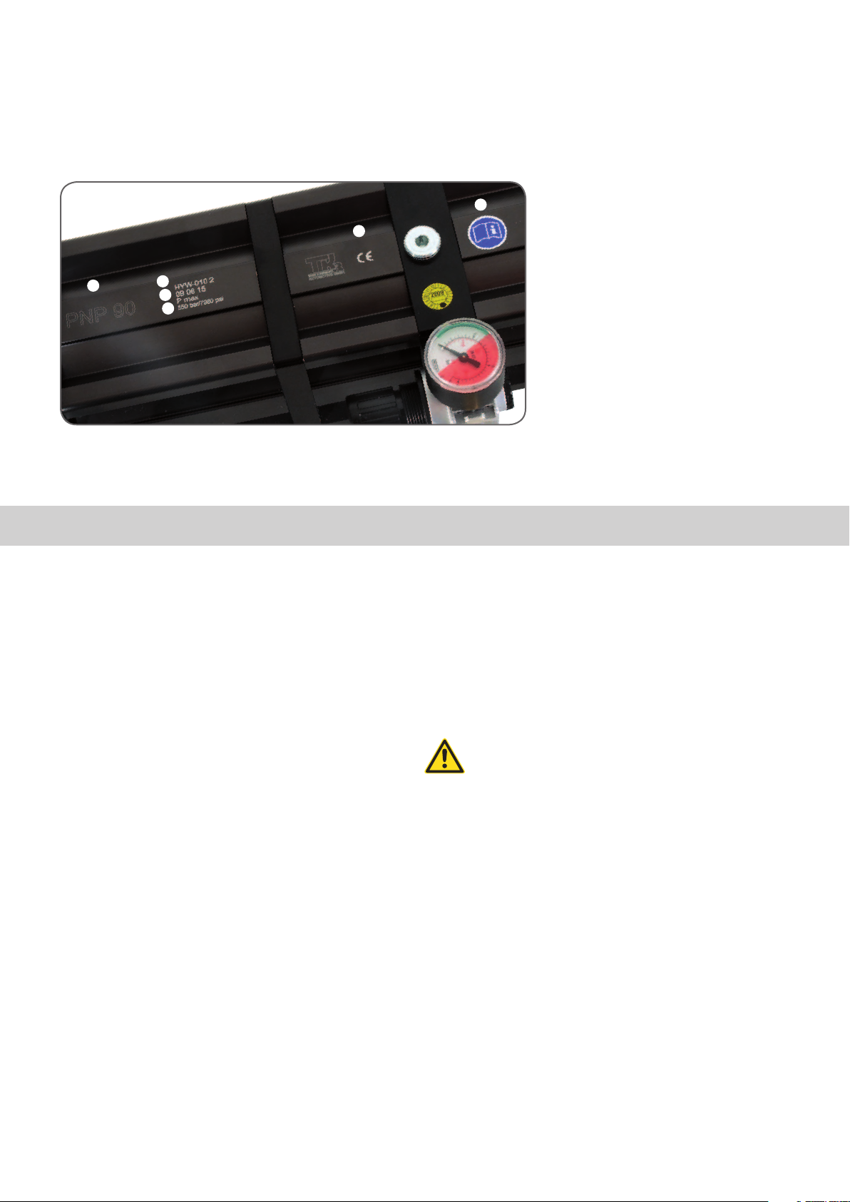
1.3 Designations
Designations on the stamping and riveting tool
1.3.1
E
A
B
C
D
2.1 Operating principles
F
A Type designation
B Serial number
C Manufacturer‘s designation,
production date
D Maximum permissible
operating pressure (oil)
E CE mark
F Symbol to read the
instruction manual
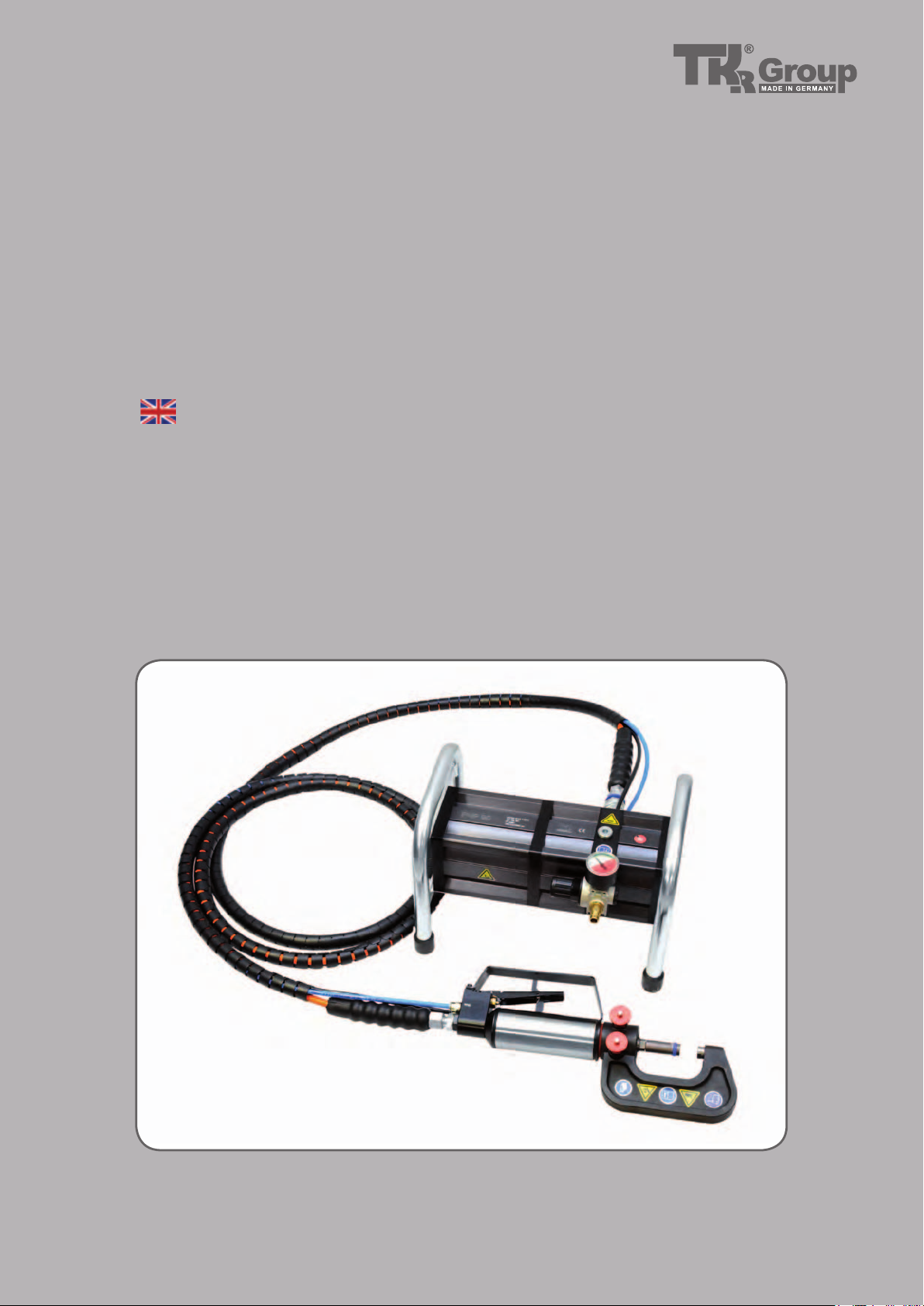
The pneumatic/hydraulic universal tool PNP90-UN 2.0
was specially developed for all common riveting operations in thin sheet metal structures.
The equipment‘s universal technology enables adaption
of various attachments for different applications.
The basic tool kit comprises the pneumo-hydraulic pressure
intensifier PNP 90 and a hydraulic actuator with hose
package. The kit is completed by an NB 40 rivet clamp
and a fully equipped RIVKIT UN 2.0 riveting tool kit.
The hydraulic pump is a pneumatically driven pressure
intensifier with a pressure ratio of 1:100. This means that
hydraulic output pressure of 600 bars is generated with
input air pressure of 6 bars. When the equipment‘s preset final pressure is reached, the pump stops automatically and keeps this pressure constant. The hydraulic pump
has a pneumatically controlled pressure relief valve.
The hydraulic actuator is connected to the hydraulic
pump via a high-pressure hose. The hose is connected
to the pump via a leak-free quick release coupling. The
coupling can only be connected to the equipment when
it is depressurised.
The two pneumatic control lines are also connected to
the pump. Make sure that the black and the blue hose
are inserted into the couplings with the relevant markings.
Compressed air can be connected to
the equipment as soon as the hydraulic
hose and the control lines are connected to
the pump.
The hydraulic actuator is equipped with a control valve that activates pump operation. The operating lever
is equipped with a safety catch to prevent unintended
operation.
If the valve is activated, the pump begins to run and the
hydraulic plunger extends.
If the operating lever is released, the pump is deactivated
and the hydraulic plunger retracts to its original position.
4
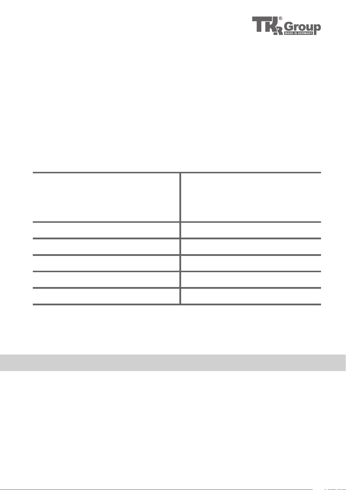
2.2 Scope of Supply and Accessories
Scope of supply basic kit PNP 90 UN 2.0
1x Pressure intensifier PNP 90
1x Hydraulic actuator HP 35 UN
1x Rivet clamp NB 40
1x Riveting tool kit RIVKIT-UN 2.0
2x Locking bolts
1x Owner‘s Manual
Technical Specifications
Permissible hydraulic oil
Max. air pressure
Accessories (not part of the basic kit)
1x Rivet clamp NB 115
1x Rivet clamp NB 230
1x Pop rivet adaptor RIVPULL 2.0**
1x Oval hole punch tool PUNCH-OV**
** in preparation
Filling capacity 280 ccm
Branded hydraulic oils as per DIN 51524
ATF as per DIN 51562-1
Viscosity approx. 68 mm²/s at 40 °C,
Example: Shell Tellus TX 68, Dexron, Mercon, Hydroclear
6 bar / 87 psi
Compressed air
Ambient temperature
Prescribed safety clothing
Noise emissions level
The effective value of the acceleration assessed at the hydraulic tool measured in accordance with ISO/FDIS B66211 is < 2.5 m/s²
Quality class 2 as per ISO 8573-1
5–50 °C / 41 –122 °F
Protective gloves, face mask
LPAI < 75 db(A)
5
2.3 Safety instructions
The hydraulic tool kit is strictly approved only
for the purposes intended by the manufacturer.
Only genuine accessories may be used. Use
of non-genuine tools or accessories presents a
major safety hazard.
Ensure that only trained and instructed
personnel use the equipment!
Use of the equipment by personnel that have
not been trained and instructed is prohibited.
Ensure that the instruction manual is made
available to operating personnel.
Observe the applicable national regulations for
prevention of accidents.
Do not use any hoses or fittings that are not
permitted for the equipment's operating
pressure.
Protective gloves and a face mask must strictly
be worn for all applications of the equipment,
because metallic parts can break up and fly
off with high energy if the tool is faulty or
operated incorrectly.
As a result, there is a risk of severe bodily injury!
See also ANSI Z87.1-1989.
Never throw the tool or allow it to fall.
Never misuse the tool or lend it to untrained
personnel.
The tool must only be used in ambient
temperatures of above 5 °C and up to a
maximum of 50 °C.
The tool must never be used in potentially
explosive areas.
6
2.4 Principles for Handling
the PNP 90 UN 2.0 Tool Kit
Risk of injury
Route all supply lines in a manner that prevents
people from tripping over them. Correctly route and attach the compressed air hose. If a
compressed air hose whips around wildly, it
could cause severe physical injury.
Before starting work, check the preset air
pressure! Incorrectly set air pressure could
cause equipment damage or physical injury!
Max. air pressure
Make sure that the maximum permissible operating air pressure of 6 bar / 87 psi is never
exceeded. Check the setting of the pressure regulating valve before each riveting operation!
Clean compressed air
Make sure that the pump is always supplied
with clean and dry compressed air. Moisture
and contamination could cause equipment
malfunction and/or damage. Only use compressed air of quality class 2 as per ISO 8573-1.
Warranty
The manufacturer accepts no liability for damage
or injury caused by improper repair or use of replacement parts made by other manufacturers.
Incorrect usage of the riveting tool that leads
to equipment damage invalidates the warranty.
Declaration of Conformity
6.4
Riveting tool PNP 90 UN 2.0 has been tested
and manufactured in accordance with European
guidelines. The Declaration of Conformity has
been included with this instruction manual.
The compressed air supply must be disconnected from the equipment before
any adjustment or maintenance work is
performed.
Always disconnect the riveting tool from
pressure when leaving the work site!
7
2.5 Maintenance
The tool‘s hydraulic system, pneumatic
control sys tems, hoses and couplings
must all be kept free of dirt and other
contamination. Foreign bodies in the hydraulic fluid or in the control air can cause the tool system to malfunction.
All maintenance and service work on the
stamping and riveting tool must only be
performed with the pump disconnected.
All maintenance and service work on the
pump must only be performed with the
air disconnected and the oil drained.
Normally, pump maintenance only entails a re-
6.1
gular oil change (see 2.2 for permissible oils).
All other necessary maintenance work and/or
repairs should be performed by the manufacturer or properly trained personnel.
Oil that is not properly disposed of could
harm the environment.
The user must only perform the maintenance
and repair measures outlined in this instruction
manual.
Maintenance and repair work not covered in
this instruction manual may only be performed
by professionals with proper training by TKR.
For further information on servicing and training, please contact us at our Service address:
TKR Automotive GmbH
Am Waldesrand 9–11
D-58285 Gevelsberg (Germany)
Phone +49 2332 66607-60
Fax +49 2332 6 66 07-90
Email info@www.tkrgroup.com
Internet www.tkrgroup.com
With normal use of the pump, hydraulic oil
should be changed every 80 operating hours
or every 12 months. Make sure that used oil
is disposed of as required by national environmental legislation.
8

2.6 Warranty
Stamping and riveting tools from TKR Automotive GmbH come with a 12-month warranty against material and manufacturing defects.
This does not cover wearing parts (rivet mandrels, rivet dies, spacing bolts and spacing
sleeves) or hydraulic oil.
The warranty period begins on the date of delivery, as specified on the invoice or delivery note.
The warranty is valid for the user/customer provided that the tool is obtained from an
authorised sales outlet and is used as described in the instructions and for the purposes
for which it was designed.
The warranty becomes invalid if the tool is used for purposes other than those for
which it was designed.
In addition, the warranty becomes invalid if the tool is not used as described in the
instruction manual.
In the event of defect or fault, TKR Automotive GmbH shall only repair or replace faulty
parts at its own discretion.
Your supplier and service partner:
TKR Automotive GmbH
Am Waldesrand 9–11
D-58285 Gevelsberg (Germany)
Phone +49 2332 66607-60
Fax +49 2332 6 66 07-90
Email info@www.tkrgroup.com
Internet www.tkrgroup.com
9
104.7
246.5
50
50
104.7
246.5
50
330
213
330
213
230
213
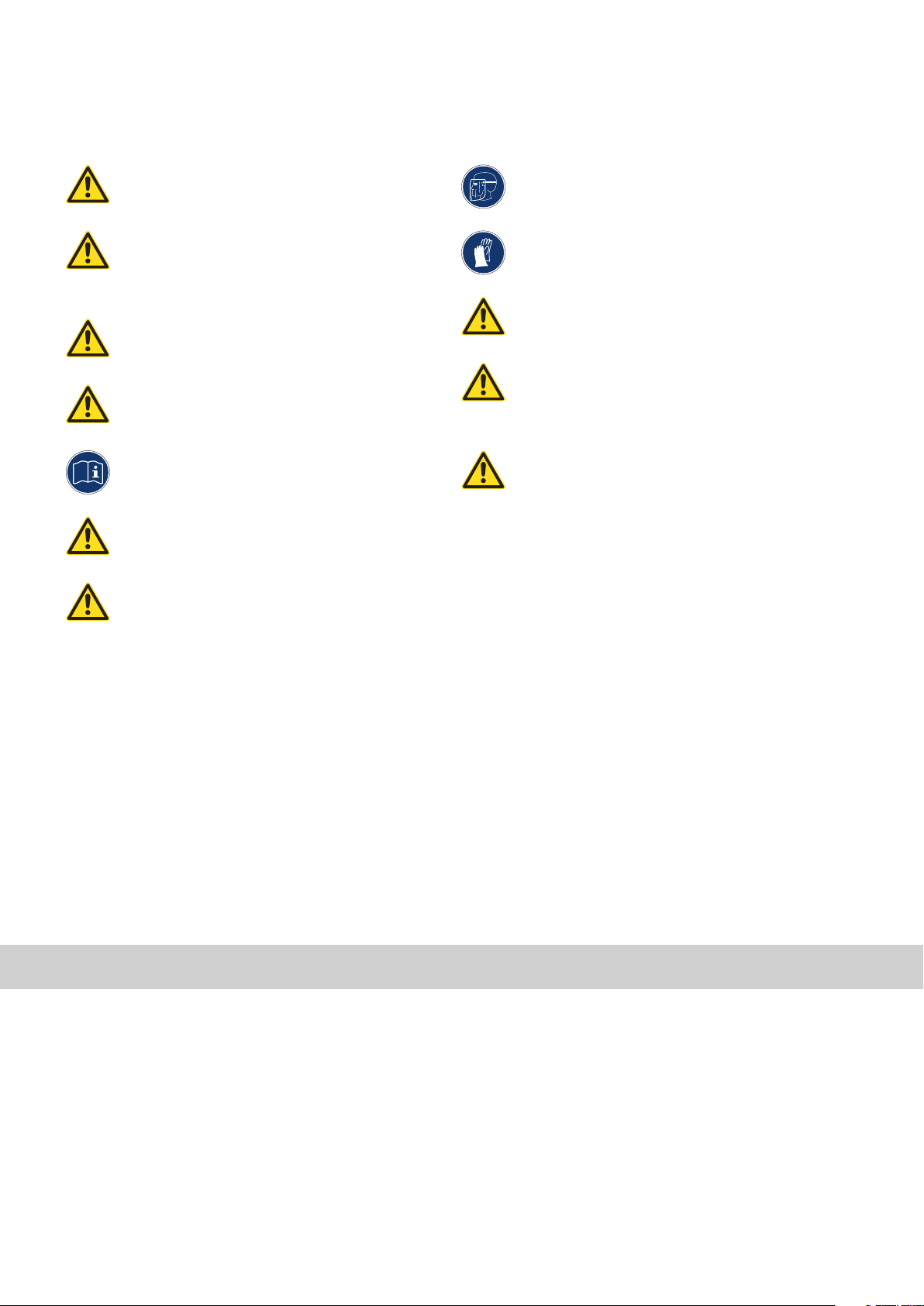
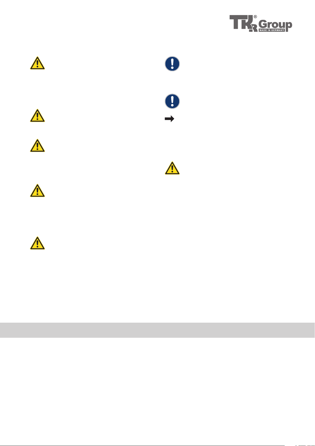
3.1 Technical Data Pump PNP 90 UN 2.0
3.1.1
3.1.3
3.1.2
Pump PNP 90 UN 2.0
Length
Width
Height (incl handle)
Weight
Max. input pressure
Max. operating pressure
330 mm
230 mm
213 mm
8 kg
5.5 bar
550 bar
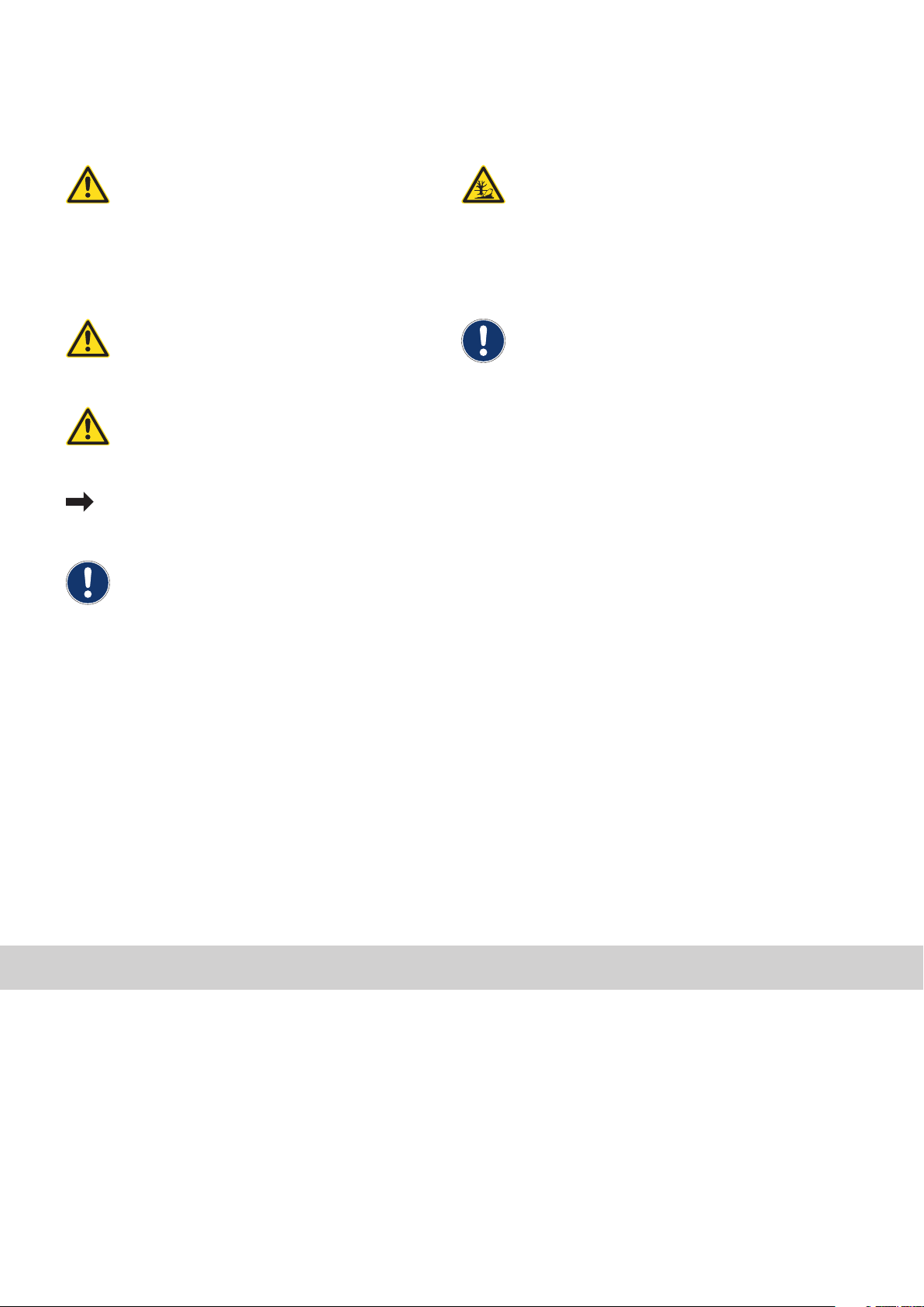
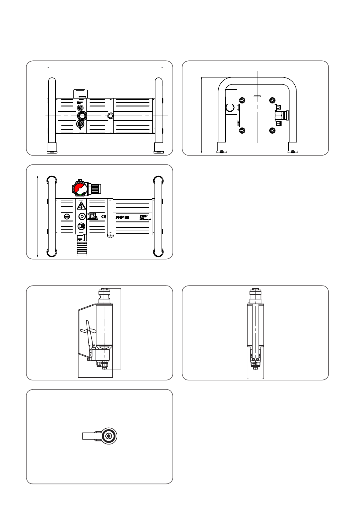
3.2 Technical Data Hydraulic Actuator HP 35 UN
3.2.1 3.2.2
3.2.3
Hydraulic actuator HP 35 UN
Length
Width
Height (incl handle)
Weight
Max. operating pressure
Travel
Length and weight without hoses
246.5 mm
50 mm
104.7 mm
2 kg
600 bar
15 mm
10
 Loading...