

Page 1
Public address systems
& Commercial sound systems
MC-300A
Conference system
www.t-koko.com
Page 2

MC-300A
Discuss/Voting/video/simoutaneous interpretation conference system
Welcome to use computer management conference series.Simultaneously,thanks for your
trust and patronization. This is a s high grade conference system featuring big power, good static
noise , anti-interference, widely used. This system is suitable for all kinds of conference
applications.
Main features
z The Control Main Unit handling power 400W, supporting up to 60 Groups of delegate
and chairman speech units, and could be extended to up to 200 groups by adding more
Extension machines .
z Easy access to speech with only one key touch.
z Volume control button, built-in loudspeaker, clear sound.
z Two earphone connectors, volume controlled independently.
z Ultra-directive mic with status indicating ring (red)
z With feedback eliminator. When mic turned on the built-in loudspeaker close automatically
to avoid feedback.
z Delegates speech units controlled on number, Support many working mode: Free mode,
FIFO mode and Limit mode.
z With connector for Telephone interface input, capable of carrying out teleconference via
telephone interface.
z Chairman units free of restriction of talking quantity.
z Chairman units have priority control over conference sequence.
z Chairman units can be connected as series anywhere.
z Easy connection and maintenance with T-shape cable serial connection. Shielded by
all-aluminum foil + live wire, much possibility of interference to cable from electromagnetic
wave is reduced.
Advice
It is highly recommended that you read through this user's manual before you start to run the
machine, although you may eager to know functions of the system. Pay a special at tention to
important security information. Moreover, the conference system also has some innovative
characteristics and functions you has not possibly met, before attempting to concretely apply.
Cautions
Do not attempt to turn on the cover, there is no deposited fitting for the user inside.
Please be far away the heat , otherwise it can influence this equipment to radiate .
Please deposit in the dry place and pay attention guards against aquosity.
Please prevent the object or the liquid fall into the product.
It is forbidden to place anything may overflow liquid on the AC power source and the equipment.
Please refer to the service info for any failure of function and abnormal phenomen.
I. Computer Management Conference System
1.1 The function explanation of Main unit
a LCD display the working mode.
b Support many working mode: Free mode, FIFO mode and Limit mode.
Page 3
z Free mode: All the microphone can turn on freely at same time
z FIFO mode: first in, first out. Attendance Units (1-12 pieces) can be set to turn on and turn
off at the same time in turn.
z Limit mode: Operator can limit the number of attendance Units (1-12 pieces) that can be
turned on at the same time.
z Chairman mode (optional): There are two working mode of chairman Unit. Chairman Only
Mode: Delegate microphones are turned off and can not be turned on again after chairman
microphone press Priority button unless chairman unit turns off. Normal Mode: Delegate
microphone are turned off but can be turned on again after chairman microphone press
Priority button. (operation in computer)
z Auto-off: It can be choosen whether microphone will turn off automatically within 30 or
60seconds after speech. (operation in computer)
z Chairman indicative music: On or Off (operation in computer)
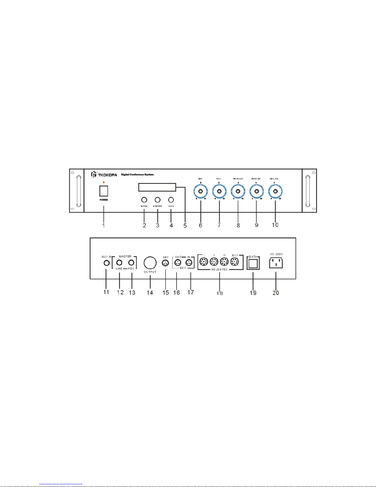
1.2 Operating diagram of main unit MC-300A
1. Power
2. Mode: Free mode, FIFO mode (1-12), Limit mode (1-12), main unit manage mode and
computer manage mode.
3. Speaking number key (NUMBER), (1-12 units)
4. SAVE
5. LCD display
6. Volume control of wire microphone (Mic)
7. AUX volume (AUX)
8. Monitor volume
9. System volume (MASTER)
10. Unit Volume
11. AUX IN
12. System line out (LINE)
13. System REC out (REC)
14. Signal out ( OUTPUT)
15. Wire microphone input (MIC IN)
Page 4
16. Effect OUT
17. Effect IN
18. Delegate Units connector
19. DATA
20. Power Jack (AC 220V/50Hz)
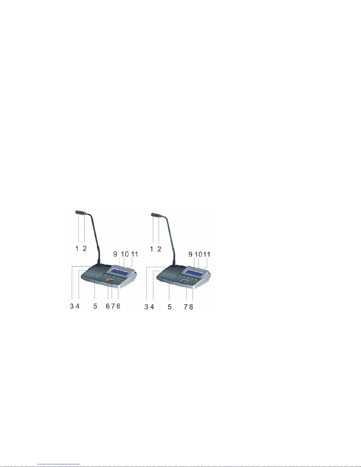
II. Operation instruction of Chairman Unit (MC-301A) and Delegate (MC-302A) Unit
1 Microphone Ultra-directional electret MIC
2 Lamp-ring. Lighting at talking status .
3 Earphone jack φ5mm
4 Wireless microphone connector for Chairman Unit; Recording output connector for the
Delegate Unit. Volume potentiometer(VOL) to adjust the volume of the loudspeaker
5 Built-in loudspeaker
6 (PRIO) priority key of chairman unit (Delegate unit without). By pressing this key Chairman
unit can turn off delegate unit.
7 Microphone switch (TALK)
8 Voting key
9 LED
10. IC CARD INTER
11. LINE
Chairman Unit
Delegate Unit
III. Extension unit function
When attendance units reach to 60 pcs, one Control Main unit can not meet the requirements,
so Extension unit is necessary to provide power supply.
z Handling Power: 400W
z 4 groups' 13P-DIN jack for the multiplex connection of the system or to connect other
Extension units.
z 220V AC power supply
z It can be set on the desktop or set into standard 19-inch rack.
z V. System has following functions when working with computer
z The operation software has simple and clear interface and are configurable instantly. Double
screen display available, Conference procedure controled by an operator.
Page 5

z Voting function
z Sign in
The indicator lamp "ATTEND" will flash when conference sign in start. Delegates sign in by
key-press and the "ATTEND" indicator in the vote unit will light, it means that delegates have
sign in. Then the vote unit can achieve other function.
z Vot e
There are five buttons on the vote unit, the first three are: yes/no/abstain. Each button has the
corresponding indicator lamp. After voting starts, delegate can press the corresponding button
according to their willing. The delegate can re-vote before the voting finishing if they want to
revise their vote; the voting results are subject to last key-press.
z Elect
The five buttons on the vote unit stand for Candidate 1/2/3/4/5. Each button has the
corresponding indicator lamp. There are three kinds elect mode optional (Three select three, five
select one, five select five). As election starts, delegate can press the corresponding button
according to their willing. The delegate can re-elect before the election finishing if they want to
revise their elect; the election results are subject to last key-press.
z Audience response
When conference start audience response, five button on the vote unit means: "--" (0),
"-"(25), "0" (50), "+" (75), "++" (100).
2. Video camera auto-track function
3. Discuss mode
z Free mode: All the microphones can turn on freely at the same time but PRIO ket of
chairman unit has effect on all delegate unit. operator and chairman unit can turn off the
delegate unit any time.
z FIFO mode: first in, first out. Operator can set the number of microphone that can be
Turned on at the same time in this mode. When talking units reach the number, the first on
microphone will turned off automatically to keep the limit microphone number.
z Limit mode: Operator can set the number of microphone that can be turned on at same time.
When talking units reach the number, the latter can be turned on only after the earlier turned
off.
z Auto-Meeting mode: Operator can set the limit time (1-250 minutes) of each delegate's
speaking. Only one microphone can be turned on at same time, but all delegates microphone
can wait to talk with requesting. The first delegate microphone can make a speech without
waiting and requesting. The system will start to count limit time automatically after the
microphone turned on and this microphone will turned off automatically after reach the limit
time. If there are some delegates wait to speaking, the delegate microphone will turn on one
by one, and the limit time start to count automatically. The operator also can force to turn off
the microphone by control panel, and the next microphone can start to speak.
z Request mode: Delegates need press "Talk" on the microphone to request speaking, all the
microphone need the operator's permit to make a speech
z Appoint addresser: Operator can appoint any mic turn on and turn off according to their
Willing
VI. System connection and debug
1. Preset conference main unit in racks or on the cou ncil board, chair man and delegate un its on
Page 6

the council board .
2. Install the conference software in the computer, plug in USB encryption software.
3. Install the video display card to the host of computer.
4. Connect projector or TV to computer ( when with vote function)
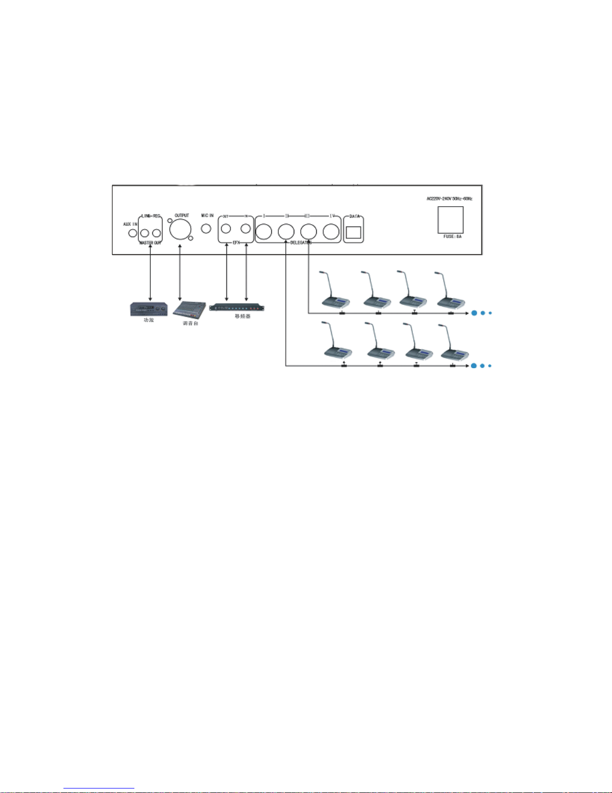
5. Please connect the male plug of extension cable (13M) to 13-DIN port (marked DELEGATES)
of the main unit.
6. Please connect male plug of T-shape main cable to the female plug of extension cable, branch
cable connect to the 13P-DIN port of the chairman unit.
7.Connect the delegate units by branch cable one by one in the system. If there are too many
conference units, please use multiplex connection way.
8.Please embedding the cable in the ground if the cable should not be seen in the meeting room.
(we will make the cable with size of conference project drawing)
9.Please connect the EFX out port of Main unit to balance input port of frequency shifter by audio
cable, connect the EFX in port to balance output port of frequency shifter by audio cable. (if
frequency shifter available)
10.Please connect mixer to output port of main unit if user use mixer.
11.Please connect the amplifier to LINE port of main unit
12.Please connect the speaker to the amplifier.
13.Please connect the recorder to REC port of main unit
14.After connect the system well, turn off the power of the system (the main unit) and debug the
main unit volume (VOL.) to minimum position, other volume control to middle position.
15.Connect the power cable to the main unit and Power supplier, and then turn on the main unit to
check the power indicator.
16.Turn on one microphone; debug the volume by VOL control of main unit to make sure the
system volume is suitable for speaking and listening.
17.Please test the function of main unit one by one first according to operation instructions.
18.System working mode setting: Press MODE key of the main unit, the LCD will display the
mode: Free, FIFO, Limit, Number, Panel and PC mode. Please press SAVE key after user select
the mode, then the LCD will display " MODE ALREADY SETTING"
Main unit control mode:
a. Press MODE key to select the LCD display "Panel mode"
b. Press SAVE key to save the select
c. Press MODE again to select the working mode: FREE, FIFO, LIMIT mode.
d. Press SAVE key to save the setting, if user select FIFO or LIMIT mode, then continue e and
f step, if select FREE mode, then the setting is finished.
e. Press MODE key to LCD display NUMBER, and press number key to set the number (1-12).
f.
Press SAVE key to save the setting
PC control mode:
a. Press MODE key to LCD display "PC MODE"
b. Press SAVE key to save the setting. The LCD will display" welcome to use PC mode" after
setting finished.
Page 7
Schematic diagram
DIGITAL CONFERENCE SYSTEM
SOFTWARE
Part A: System requirement:
Hardware required
Processor: Intel Pentium 4 or AMD Athlon XP, 2 GHz or more
RAM: 256 MB min. (512 MB recommended)
Hard disk: Min. 15 MB free hard disk memory
Drives: CD ROM or DVD ROM drive
drive for data backup (e.g. floppy disk drive,
CD recorder or ZIP drive)
Interfaces: At least one free RS 232 interface (serial interface)
Sound card: quality stereo sound card
Screen resolution: Exactly 1024 × 768 pixels
Display: Double display card (Please see the instruction belows)
Part B: Installation and Removing
Installing the software
Page 8
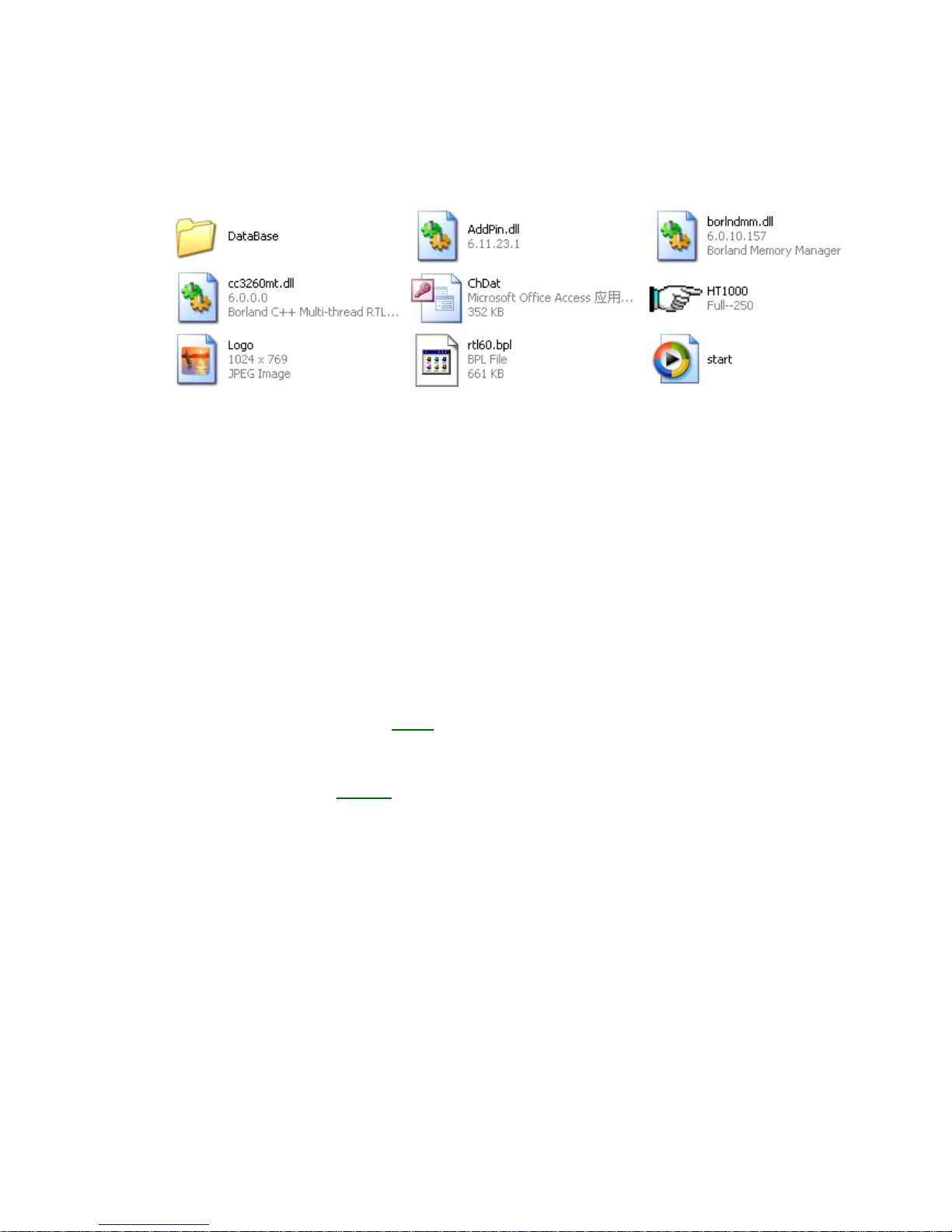
To install the “KO-1000” software on the hard disk of your computer, proceed as
follows:
1. Insert the software CD into the CD-ROM drive of the computer, double-click the
“My Computer” icon on your desktop and then click the icon for your CD-ROM drive.
2. Because “KO-1000” is a green software, user can copy the file from software CD to
computer or run it directly.
Removing the software
To completely remove the KO-1000 software from the hard disk of your computer,
please choose the files that user copy from software CD and delete them. KO-1000
software is removed from your computer.
Install video display card and setting
Video display is used to transmit the signals of voting or electing results. We
recommend customer to use our video display to configure the computer.
1. Specification of the video display card
Description: Radeon 9000 PCI 32MB
DDR
Manufacturer: ATI
Type of Video Card: Graphics Accelerator Card
AGP Support: AGP 2X, AGP 4X
Color Depth at Maximum Resolution: 16.7 Million Colors (32-bit)
Interface Type: Video - 15 pin High-Density D-shell (VGA)
Refresh Rate at Max Resolution: 60 Hz
Resolution: 1024 x 768 (XGA), 1280 x 1024 (SXGA), 1600 x 1200 (UXGA), 2048 x
1536
Slot/Port Type: PCI
System Type: PC
Video Chipset: ATI RADEON 7000
Installed Video Memory: 32 MB
Memory Technology: DDR-SDRAM (DDRRAM)
2. Please install the video display to the computer, and then install the driver.
3. Schematic diagram of the video display card
Page 9

① connect computer display ①
② Connect TV
③ Connect the projector ②
④ AGP
③
④
4. The system will search the second display after user connects TV or project to the
video display card.
5. Please click right mouse on desktop, choose “Properties to enter the “Display
properties” panel.
6. Click “Settings” to enter the setting panel, choose set the Screen
resolution: 1024 by 768 pixels, Color quality: highest (32 bit), and then tick off
before “Extend my windows desktop on to this monitors” .
Page 10
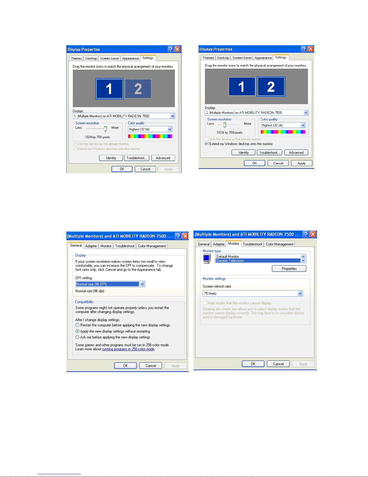
7. Click “Apply”, then the second display (TV or projector) has already setting.
8. If the second monitor still can not display normally, please resetting as process 5
and 6, then click” Advanced” icon to enter the “multiple monitors’ , choose “monitor”
to debug the setting.
Part C: Operation
Log on
1. Make sure the software Dongle connects to the USB interface of computer;
please do not remove the dongle from your computer when run the software. (Fig
1)
Page 11
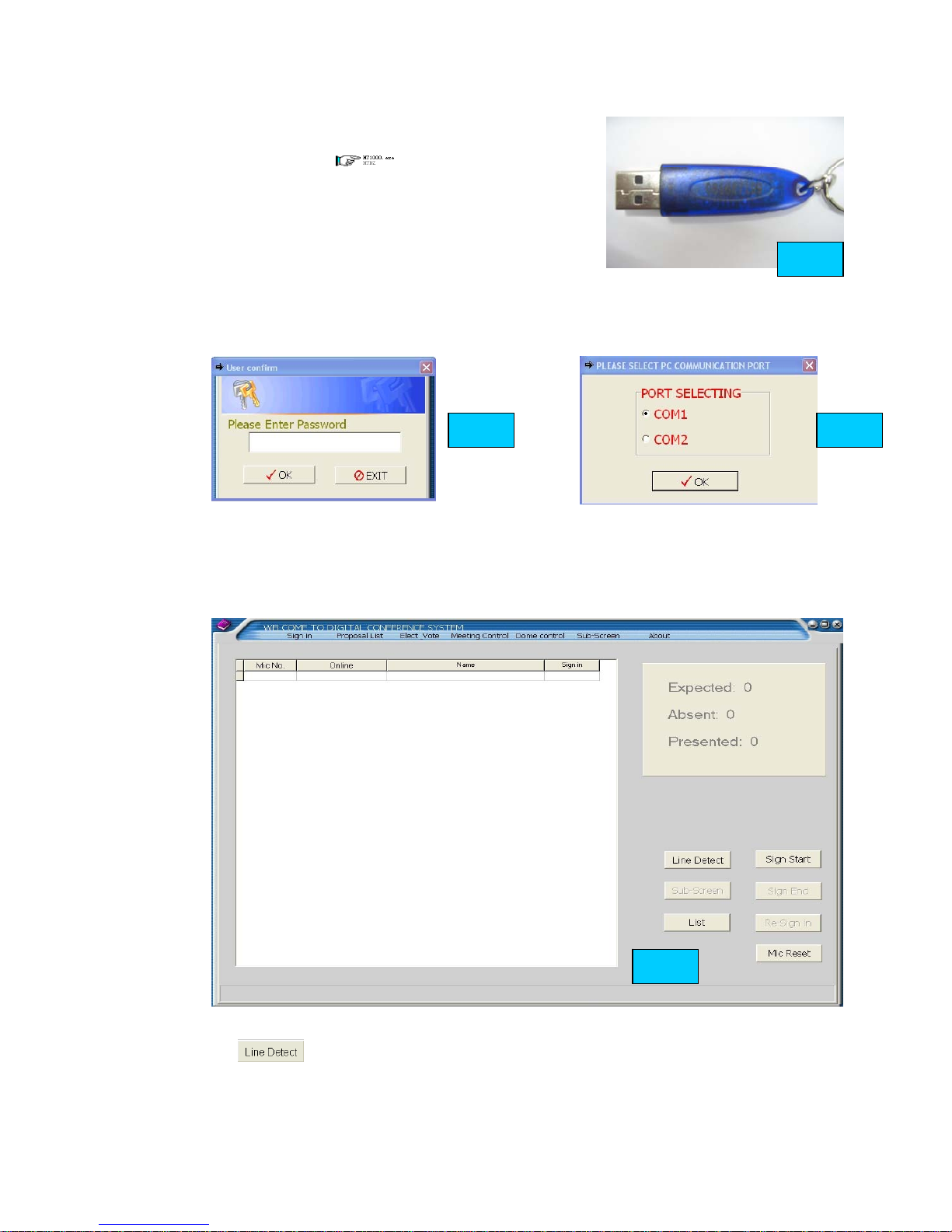
2. Make sure that conference system main unit and
microphone already connected. Double-click the
program icon to run the software.
Please enter the password (original password is “1234”)
to choose the communication port (Fig 2. 3). The
system will check the hardware after user chooses the
communication port. ( if the conference system
disconnect , the system will display the message to
suggest user check the connection and power) (Fig 4) The software will enter the
main panel after user chooses and check the communication port.
Main panel of the software
There are seven parts in the software main panel” Sign in”, “Proposal list”, “Elect &
Vote”, “Meeting control”, “Dome control”, “Sub-screen” and “About” (Fig 5)
Sing in
1. Click to detect the microphone connection in the system. The system
will display the results automatically after click line detect. (Fig 6) Microphone not
online means that microphone has problem or disconnected.
Fig. 1
Fig. 2 Fig. 3
Fig. 5
Page 12
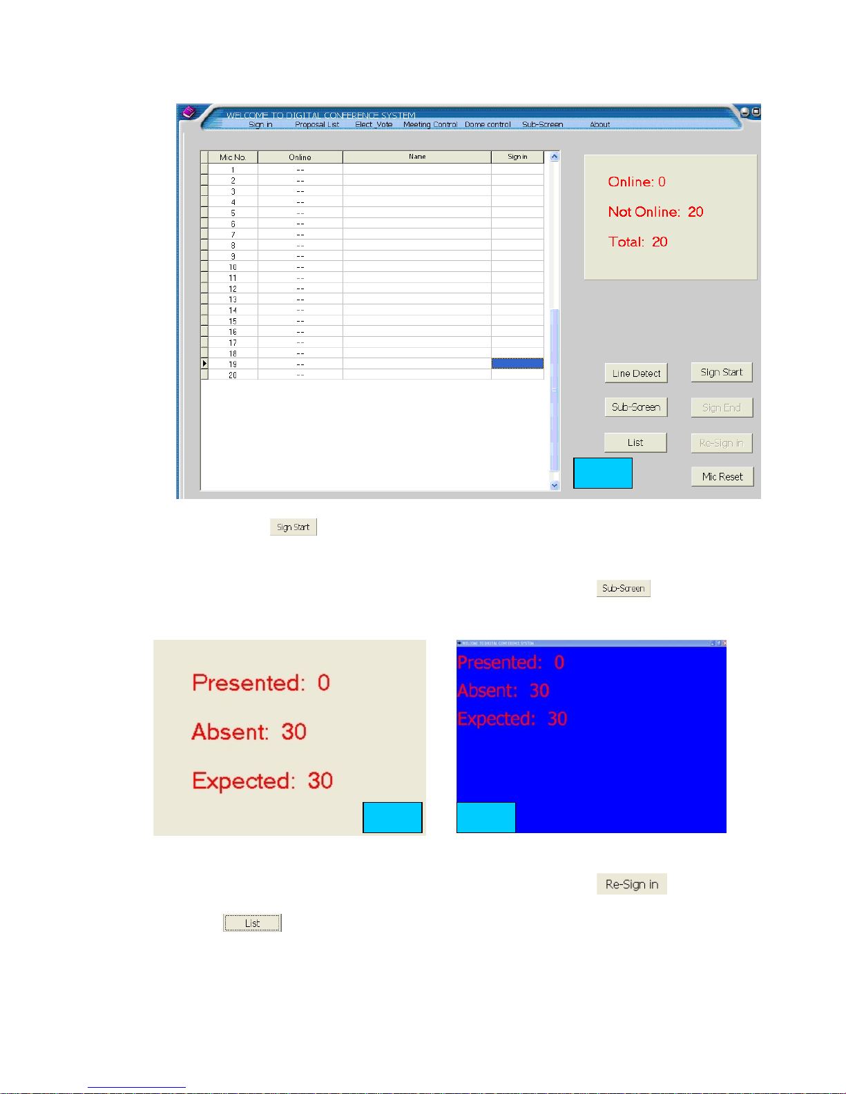
2. Please click to start sign in; the screen will display “start sing-in”,
the delegates can use IC card or press “attend” to sign-in.
3. Please click “Sign-in End” to end Sing-in, the results will display in the software.
(fig 7)
4. The sign-in results will displayed in the sub-screen if user click (fig 8)
5. If any delegates not sign-in or late for sign-in, user can click
then the not sign-in person can resign-in by IC card or key-press.
6. Click to enter the delegate list management panel. (Fig 9). User
can set the attendance, choose delegate list, modify name, add delegate, delete
delegate in this panel.
Fig. 6
Fig. 8 Fig. 7
Page 13
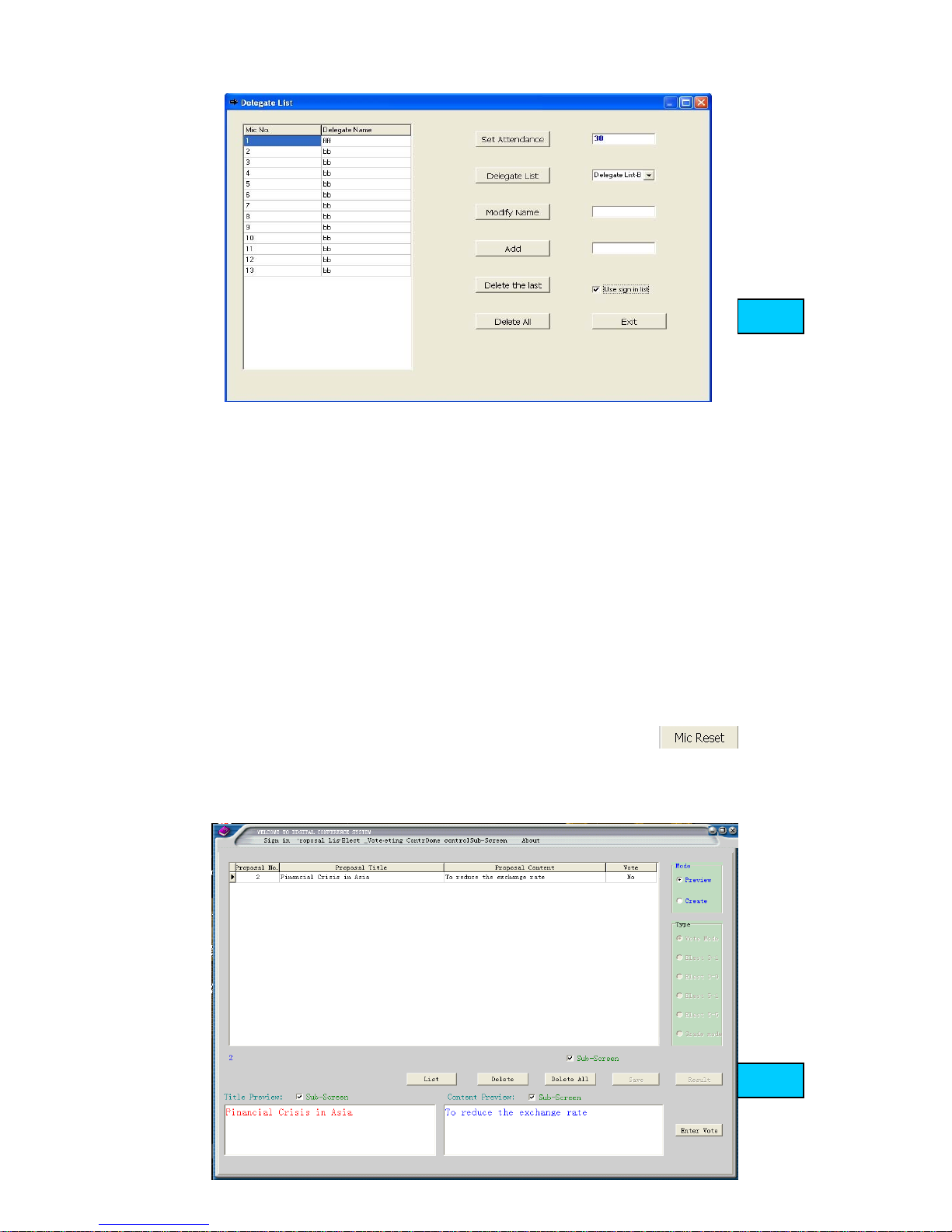
a. Set attendance: please input the attendance number of the meeting in the box,
and then click” Set Attendance” icon.
b. Delegate list: please choose the delegate list (A-D) in the list box, and then click
“Delegate list” icon to finish the choice. Please choose candidate list (A-D) when
Voting and electing.
c. Modify Name: Please choose the delegate name in the delegate list, and then
modify the delegate name in the box, then click “Modify name” icon.
d. Add: please input the delegate name in the box, then click “Add” icon to add the
delegate in the list.
e. Delete the last: user can delete the last delegate in the list after click this icon.
f. Delete all: all delegates will be deleted in the list when user clicks this icon.
g. After use set the list, please tick off “use delegate list”
h. Please click “exit” to return the ‘Sign in’ panel after use set the delegate list.
7. System microphone will be initialized and reset when user click
Proposal List
Click “Proposal list” to enter the proposal panel (Fig 10).
Fig. 9
Fig.10
Page 14
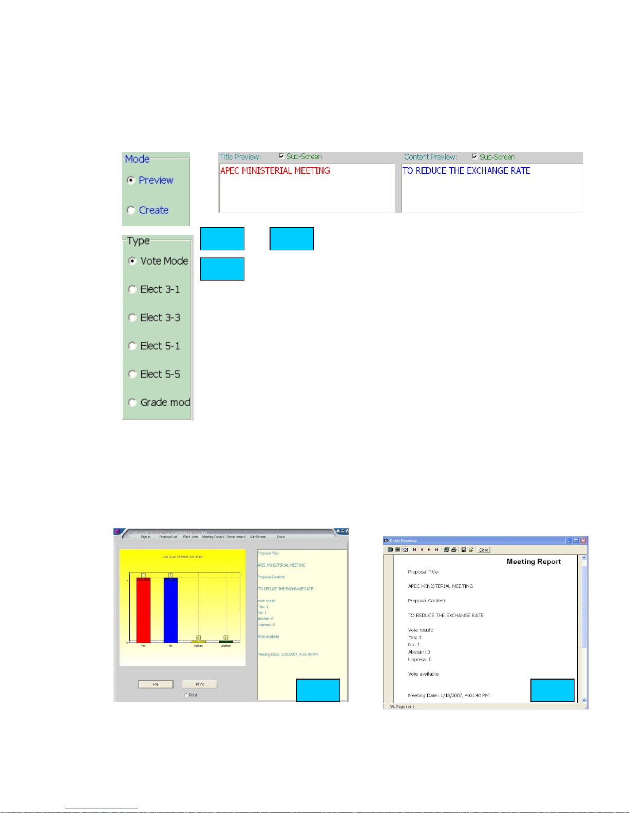
1. User can preview the proposal list in this panel, if use wants to create a new
proposal. Please click “create”. (fig.11)
2. User can set the proposal type, input the proposal title and content when the
panel in proposal create mode. (fig 12. 13)
a. vote mode: only for voting “ yes, no, abstain”
b. 3 select 1: only one candidate can be selected among the 3
candidates, same as voting. (Single-ballot)
c. 3 select 3: 3 candidates can be selected at same time
(Multiple-ballot)
d. 5 select 1: only one candidate can be selected among the 5
candidates. (Single-ballot)
e. 5 select 5: 5 candidates can be selected at same time
(Multiple-ballot)
f. Grade mode: To mark a score for a proposal: - -/-/0/+/++.
3. After user set the proposal type, title and content, then the proposal can saved
by “save” icon. User also can delete the proposal in “preview mode”.
4. User can choose the proposal and click “result” to see the voting or electing
results if the proposal already voted or elected. (Fig. 14).User can see the voting
or electing results in “Pie/Bar” display and words.
5. User can print the meeting report to save the results. (Fig 15)
Fig.11 Fig.12
Fig.13
Fig.14 Fig.15
Page 15
6. List setting in this part is same as item 6 in “sign-in” panel. Please choose
candidate list (A-D) when Voting and electing.
Vote & Elect
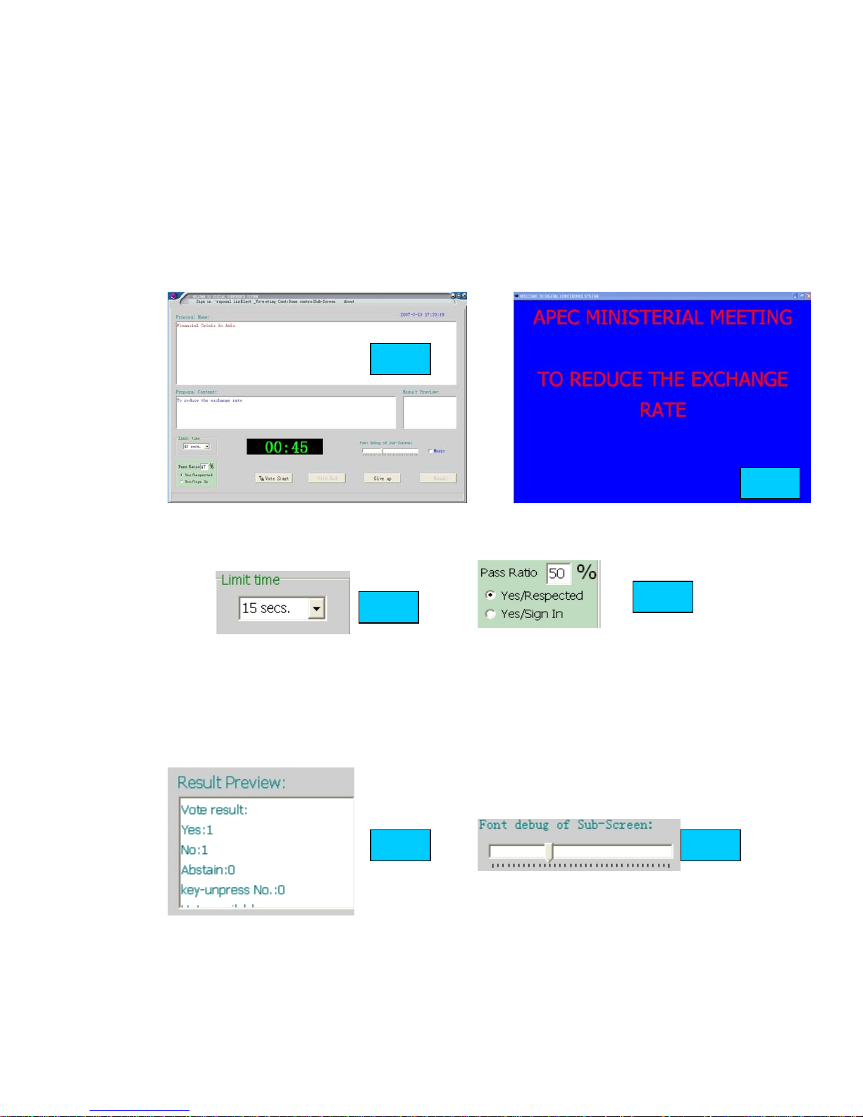
Please choose one proposal that you want to vote or elect in proposal list panel. Then
click “enter vote” or “enter elect” to enter the “vote & elect” panel. The sub-screen
will display the proposal title and content if user setting “sub-screen” (Fig 14 15)
1. User can set the vote/elect limit time and pass ratio of the proposal. (Fig.16. 17)
3. After setting the limit time and pass ratio, please click “Vote/Elect Start” to
start voting or electing, and the software will start to count the limit time
automatically, user can end the vote/elect by “Vote/Elect End” icon any time.
4. the Vote/elect results will display in “ results preview” textbox.( Fig 16)
5. User can debug the font size displayed in the sub-screen. (Fig.17)
5. User can check the vote/elect results by “result” icon; the operation way is same
as item 4-5 in “proposal list” part.
6. If users choose the wrong proposal or want to return the proposal list panel or
other panel, please click “Give up” icon, then choose other panels in the top of the
Fig.14
Fig.15
Fig.15
Fig.15
Fig.16 Fig.17
Page 16
software.
Meeting Control
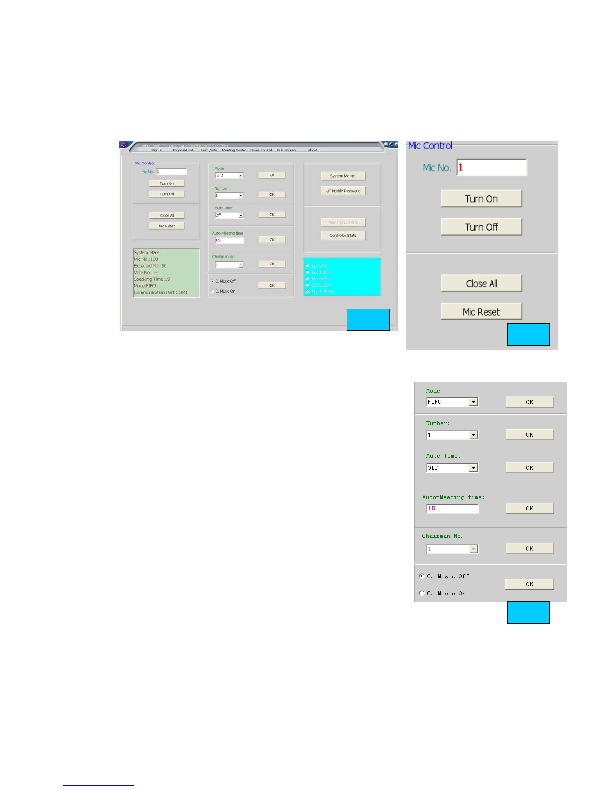
Please click” Meeting Control” in the top of the software to enter the main panel of
meeting control. (Fig.18)
1. Microphone control: this part is for user easy to control the meeting. (Fig. 19)
a. Please input the Mic No.( each microphone has one ID or
No. ) in the test box, then click “turn on” icon, that
microphone will turn on to enter speaking state.
b. If user want to turn off the microphone when it’s on,
please input the Mic No.( each microphone has one ID or
No. ) in the test box, then click “turn off” icon, that
microphone will turn off to .
c. User can click “close all” icon to turn off all the
microphone in the system.
d. Mic Reset: System microphone will be reset and
initialized to the first time that system turn on.
2. This part is for user setting the working mode of the
system.
a. FIFO mode: first in, first out; first indicators, first
offers. Operator can set the number (1-9) of microphone
that can be turned one at same time in this mode
b. Limit mode: Operator can set the number of microphone (1-9) that can be
turned on at same time. For example operator set 3, then only 3 microphone
can be turned on at same time
c. Free mode: All the microphones can turn on at same time. User can set the
auto-close time (Mute time 15 secs. 30secs. 60secs.) in this mode,
Microphone will turn off automatically if there is no action of this microphone
Fig.18
Fig.19
Fig.20
Fig.19
Page 17
within the setting time.
d. Chairman Only: Delegate microphone can not be turned on again after
chairman microphone press Priority button. The chairman need quit this mode
first, and then delegate microphone can be turned on again.
e. Request mode: Delegates need press “Talk” on the microphone to request
speaking, all the microphone need the operator’s permit to make a speech.
Operator can control the microphone state by “close all, turn on, turn off”
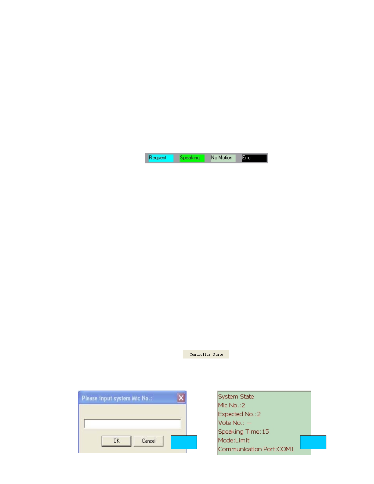
icon. The following icons are the state of microphone. (speaking Mic: Green
color; Next speaking Mic: Yellow color; Request Mic: Blue Color; No motion:
Grey color), the Mic indicator lamp will be on the Mic speaking, and the
indicator lamp of next speaking Mic will be flash.
f. Auto-Meeting mode: Operator can set the limit time of each delegate’s
speaking. Only one microphone can be turned on at same time, but all
delegates microphone can wait to talk with requesting. The first delegate
microphone can make a speech without waiting and requesting. The system
will start to count limit time automatically after the microphone turned on
and this microphone will turned off automatically after reach the limit time.
If there are some delegates wait to speaking, the delegate microphone will
turn on one by one, and the limit time start to count automatically. The
operator also can force to turn off the microphone by control panel, and the
next microphone can start to speak.
g. User can set the chairman Mic number and music of the chairman unit in this
part.
3. System Mic No.: this function usually used when install the system, the
software will display Fig 21 when click “System Mic No.”, please input the
system microphone number (include delegate and chairman microphone), then
click OK to finish the setting. The system microphone number will not setting
again except the system mic number changed.
4. Modify password: please enter the original password to setting the new
password.
5. Controller state: please click
to check the controller
current state, the state information will display in Fig 21.
6. Meeting control: Please click “ Meeting control” icon to enter the main panel
of meeting control.(Fig 22)
Fig.20 Fig.21
Page 18
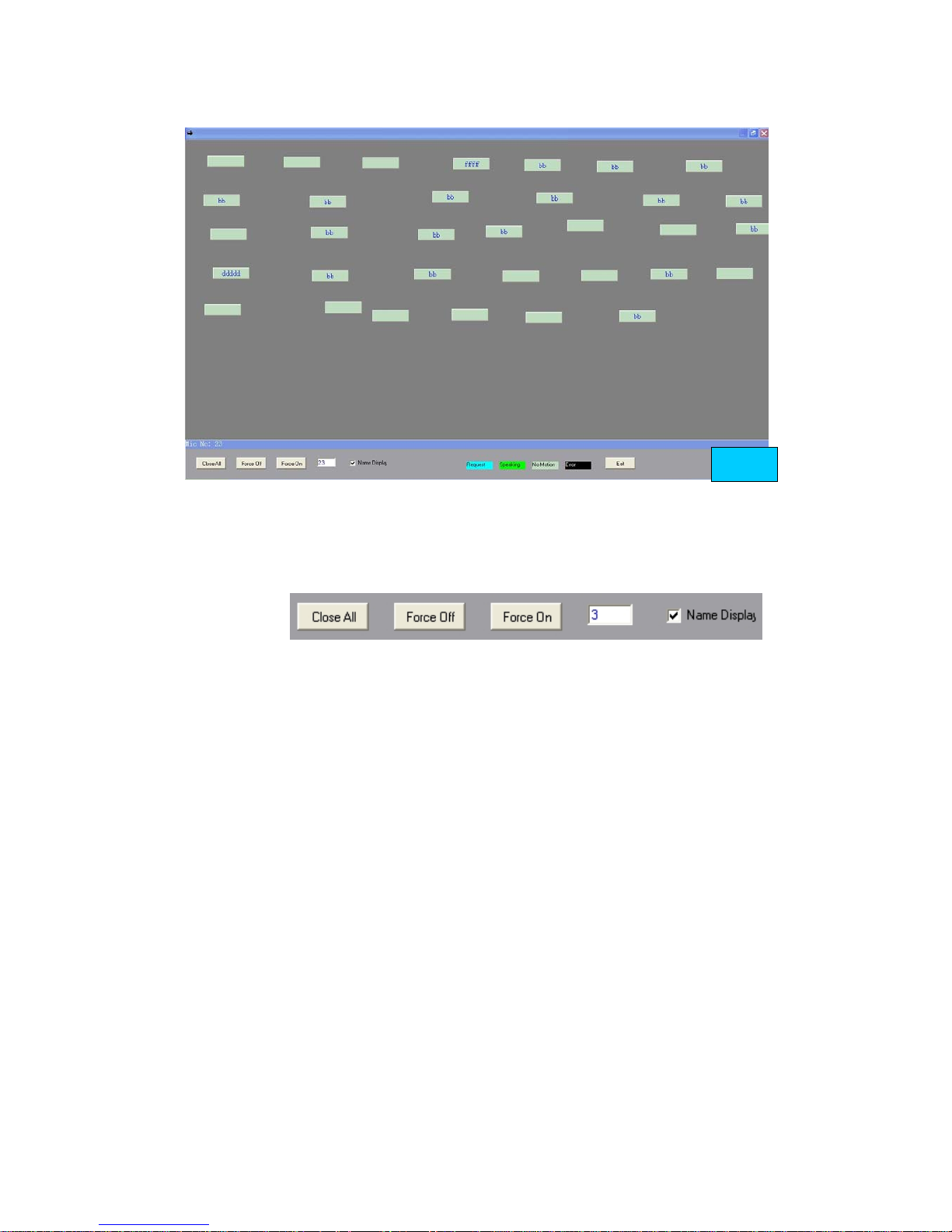
Operator can control the state of microphone with this panel, such as Display the
delegate’s name on the box icon, operator need to click the microphone icon first
before he control that microphone. Please see the following function keys:
a. Close all: User can turn off all the microphone with this icon.
b. Turn off: Operator need to click the microphone icon (the icon will display the
microphone ID or delegate name) first before he control that microphone, or
input the Mic ID in the textbox, then click “turn off”, that microphone will be off.
c. Turn on: Operator need to click the microphone icon (the icon will display the
microphone ID or delegate name) first before he control that microphone, or
input the Mic ID in the textbox, then click “turn on”, that microphone will be on.
d. Name Display: the microphone icon will display the delegate name after tick off
“ name display” when user enter this panel next time.
e. Please click” Exit” to quit this panel to return the main panel.
Dome Control
Please click” Dome Control” in the top of the software to enter the main panel of
dome control. (Fig.23)
Fig.22
Page 19
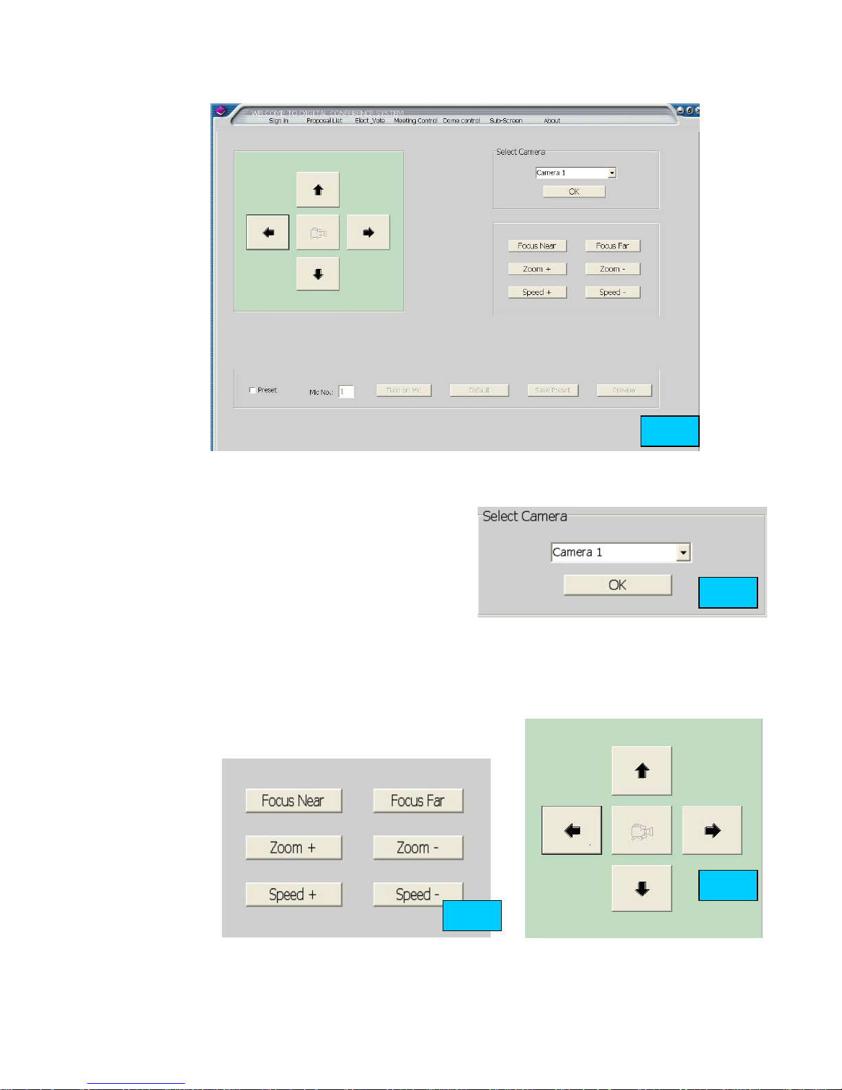
1. Please select the camera number in Fig 23.
2. Please tick off “Preset”, the system
will display a message (Fig 24), please
check that the system working mode
is FIFO, please click “yes’ if the
system in FIFO mode if the system
working mode is not FIFO, please set
this mode in “meeting control” panel first, we recommend FIFO number is
“1”.
3. Turn on one microphone by “Talk” key first (or input the Mic ID in the
Mic number textbox, then click “Turn on” the mic), please debug the
camera with the software in fig 24 and 25 to get the clear image.
4. P
l
e
a
s
e
click “Save preset” to save the preset data after user finish the camera
debug setting of that microphone
Fig.22
Fig.23
Fig.24
Fig.25
Page 20
5. Repeat the operation to finish preset all
the microphone.
6. If there is mistake in preset, please click
“Default” to preset the data again.
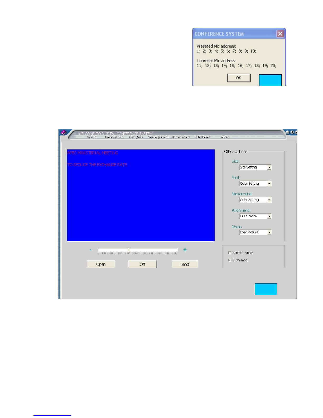
7. Please click “Preview” to check the
preset and un-preset microphone
address.,( fig 26)
Sub-Screen
Please click” Sub-Screen” in the top of the software to enter the control panel of
Sub-screen. This panel is used for display the contents in the meeting (fig 27)
1. Open the Sub-screen.
2. Size: Please select the sub-screen resolution (size) in the left part of
this control panel. Projector usually select 800*600, TV usually select
640*480, please select the correct screen resolution for the display
equipments.
3. Font: this is used for select the font color.
4. Background: this is used for select the color of sub-screen background.
5. Alignment: this is used for setting the font alignment.
6. Photo: User can select the picture send and displayed in sub-screen.
Fig.26
Fig.27
Page 21

7. User can input the content in the right top screen of this panel. And
debug the font size in fig 28.
8. Please click” send” to send the content to the Sub-screen.
About
User can enter About panel to exit the software or click to exit the
directly.
Note:
a. Please make sure that video processor and conference main unit is turn on before
preset the video function.
b. Please make sure that video processor is in preset state before preset the video
function.
c. The data will download to the processor after user preset the microphone. It’s
unnecessary to preset again in next meeting if the microphone position not
change.
d. If the conference main unit power off during the operation, please exit the
software and enter again.
DIGITAL VOTING SYSTEM
This voting system is suitable for the People's Congress, Government,
enterprises, etc. The delegates can register, vote, elect, and participate in the
democratic meeting on seat. This system is with multiple functional, reliable, steady
and attractive designs. The quantity can be from dozens to thousands of people
according to the conference requesting.
1. SYSTEM CONFIGURATION
Each central processor equipped with two output ports, and every channel could
connect up to 64 units. The system could be extended up to 4096units. The system
including software, central processor, vote unit, IC-card, and computer, etc. Adopt
T-type connection, it’s easy to install.
Vote software
The system software is working with security, reliability, convenience, and
simplicity. All operation windows are very simple, which is more suitable for
operation. The operator could control the state of vote units easily. (Please
operation software with the instruction manual)
Central processor
The central processor provides power to the vote unit and collects the voting
data.
Fig.28
Page 22

Vote unit
The vote unit has the following functions and characteristics (The functions of
the vote unit may have some differences because of the models)
1). Discern the identity
Each vote unit is furnished with a personal IC card for voting (The IC card No.
should be the same as the vote unit No.), or all the vote unit use the same kind IC
card, it means the delegate can sign in by IC card with any vote units.
2). Sign in
The delegate sign in by IC card after taking a seat, the system provides IC card
ID checking. Only when IC card is well inserted and the indicator lamp “ATTEND”
on the vote unit is bright, it could work if system is equipped with IC card.
3). Voting
There are three buttons on the vote unit: yes/abstain/no. Each button has the
corresponding indicator lamp. After voting starts, delegate can press the
corresponding button according to their willing. The delegate can re-vote before
the voting finishing if they want to revise their vote; the voting results are
subject to the button pressing at the last time.
4). Election:
There are five buttons on the vote unit:: candidate 1/2/3/4/5. Each button has
the corresponding indicator lamp. After election starts, delegate can press the
corresponding button according to their willing. The delegate can re-elect before
the election finishing if they want to revise their elect; the election results are
subject to the button pressing at the last time.
5). Audience response
To mark a score for something or someone: - -/-/0/+/++.
z COMPUTER
1). Display
The system connecting corresponding display device by the displaying socket, it’s
demonstrates the meeting process clearly such as meeting topic, discussion topic,
vote content, voting process and voting results, etc
2). Print
The system can prints out the vote result with the printer.
3) System management
The system has perfect self-check and management function. It can check the working
status to find out mistakes and have it revised. The operator can control all the units
by background process.
3. MC-903V
The central processor provides power
to the vote unit and collects the voting
data. The processor has four-group
Page 23
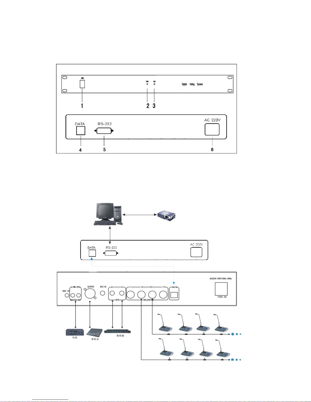
9P-DIN port for system connection. Each processor can connect 64 vote unit. The
system can support 4096 vote unit by processor series connecting. This voting system
is suitable for the People's Congress, Government, enterprises, etc. The system is
easy to install and operate.
1 POWER 2 POWER LAMP
3 BUSY LAMP 4 DATA
5 RS-232 6 AC Power
Schematic diagram
Page 24

Digital video camera auto-track Conference System
With the videoconference is more and more popularization, the requesting of the
meeting equipments are higher for the multi-functional meeting room, it need the
function of video camera auto-track in lots of the discussion meeting situation. Our
company developed the multi-functional meeting control system on the base of
summarizing the experience of videoconference and speaking system for many years.
The system control software have soft keyboard function may replace various kinds
of video-controlled keyboard, it’s more convenient to operating.
Please see the figures of Video Camera Auto-track System, before the meeting
begins, set each microphone corresponding the video recording position of the
camera. When some delegate press the speaking button to make a speech, the annular
red indicator lamp glimmers on the microphone, and the camera aims at the
spokesman automatically according to the position settled in advance. After the
delegate’s speaking, the system is turn to tracing other spokesman’s position
automatically.
★ This system include meeting host, central processor, chairman unit, delegate unit,
high-speed dome, software for system controlling and computer, etc.
A. Meeting Host
1. Designed accordance to ISO and IEC914 standards.
2. Built-in power supplying device and signal amplify, which can support more
than 60 groups of the speech equipment.
3. Four groups of 8P-DIN plugs for several systems join.
4. Can offer the power and data communication socket for video central
processor.
5. Possess the output socket of audio frequency equipment.
6. Equipped with BAL socket for connecting kinds of result device.
7. Built-in telephone coincidence for telephone meeting.
8. Built-in volume processor for volume regulating.
9. Built-in 2*50W amplifier for volume regulating.
10. Built-in monitor loudspeaker (1W) for volume regulating.
11. System volume can be regulated independently.
12. Equipped with AUX input socket and the volume can be regulated
independently.
13. Equipped with a group of wire microphones input socket, which can regulate
volume independently.
14. Equipped with nine LED system audio frequency indicator light
B. Central Processor MC-904C
1. Designed by the latest digital
technology in accordance with
Page 25
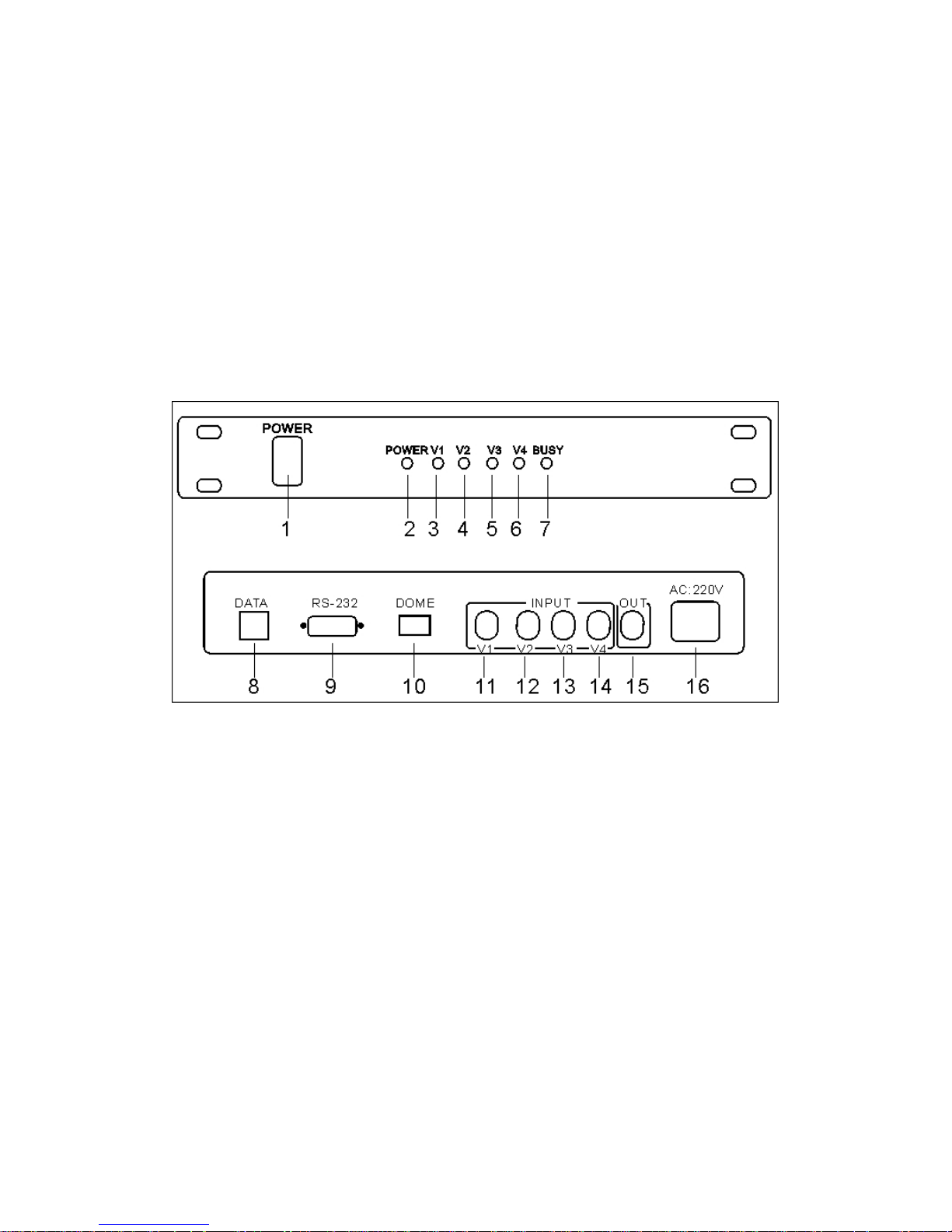
IEC914 and ISO standards
2. Many speed-dome can work at the same time. (Build-in 4 cameras, it can
expand to 8)
3. 256 video camera auto-track control points.
4. Support many kinds of dome’s communication protocols.
5. The central processor can communicate with the equipments by RS232 jack,
such computer or video switching matrixes.
6. Support many kinds of meeting mode: Free mode, FIFO mode, and limit mode.
a. Free mode: All the delegates can give a speech freely.
b. FIFO mode: First in, first out, first indicators, first offers.
c. limit mode: Can set up MIC on number (1-12) restriction
7. Build-in video switching matrixes (4 input, 1 output).
(1). Power switch ; (2). Power indicator; (3). AV1; (4). AV2; (5). AV3; (6). AV4; ( 7).
Busy led (8). Data port; (9) RS-232 port;
(10) Dome (A-G-B) A: +, B: -, G: GND
(11) V1 input; (12) V2 input; (13) V3 input; (14) V4 input; (15) Video out; (16) AC power
C. Chairman Unit
1. Designed by the latest digital technology in accordance with IEC914 and ISO
standards
2. Be with functions of speaking, listening.
3. Be with functions of video camera auto-track.
4. It does not have power equipment; the meeting host supplied the power for
all the delegate units at 24 safe voltages.
5. 8P-DIN plugs for “T” type connecting with the system.
6. Built-in high-fidelity loudspeaker and volume regulate.
7. Electric capacity type microphone, equipped with windshield cover.
8. Extended pipe optional.
9. The microphone has a speaking key (TALK) and indicator lamp to control the
state of speech.
Page 26
10. The annular red indicator lamp shows the state of the microphone.
11. The chairman unit in the system is unrestricted, can join with any position in
the circuit.
12. The quantity of chairman unit is unrestricted in the system.
13. Equipped with earphone output socket and wireless MIC socket.
14. Be with the preferential function of stop the delegates’ speech by force.
15. Be with the function of voice controlling to turn off the microphone. The
microphone will close automatically in 30 seconds after making a speech.
16. Have the precedence prelude music when the chairmen make a speech.
17. Frequency response: 100HZ to 13KHZ
18. Sensitivity: -44dB±2dB (Reference sound-receiving distance: 20 to 120cm)
19. Be with the function of “chairman only” working mode
D. Delegate Unit
1. Designed by the latest digital technology in accordance with IEC914 and ISO
standards
2. Be with functions of speaking, listening.
3. Be with functions of video camera auto-track.
4. It does not have power equipment; the meeting host supplied the power for
all the delegate units at 24 safe voltage..
5. 8P-DIN plugs for “T” type connecting with the system.
6. Built-in high-fidelity loudspeaker and volume regulate.
7. Electric capacity type microphone, equipped with windshield cover.
8. Extended pipe optional.
9. The microphone has a speaking key (TALK) and indicator lamp to control the
state of speech.
10. The annular red indicator lamp shows the state of the microphone.
11. Equipped with earphone output socket and wireless MIC socket.
12. Be with the function of voice controlling to turn off the microphone. The
microphone will close automatically in 30 seconds after making a speech.
13. Frequency response: 100HZ to 13KHZ
14. Sensitivity: -44dB±2dB (Reference sound-receiving distance: 20 to 120cm)
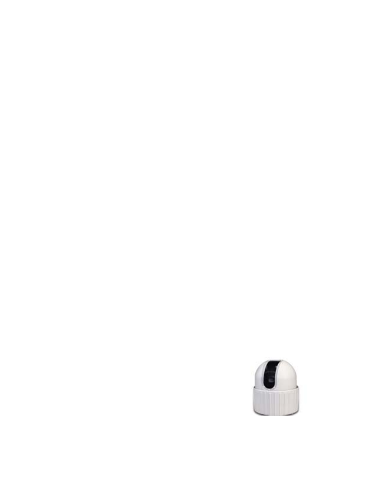
E. High-speed dome HB-906
1. 18X Auto Focus Lens: Built-in 18X optical lens
with a focal length of 4.1~73.8mm.
2. Fast Rotation: The 360 degrees seamless
rotation can rotate at up to 245 degrees per
second; can rotate vertically at 80 degrees per
second with a vertical range of 95 degrees.
3. 64 Pre-set Angles: Can be programmed and
stored for convenient monitoring anytime.
4. Up to 63 cameras: Up to 63 speed dome cameras can be connected.
5. Automatic Control and Manual Control: Shutter white balance, back light
Page 27
compensation and AGC can be set for automatic or manual.
6. Auto Monitor Mode: Automatically rotates to the present angles for
monitoring.
7. Low illumination and High Sensitivity: Can operate in illumination as low as 0.15
Lux
Note:
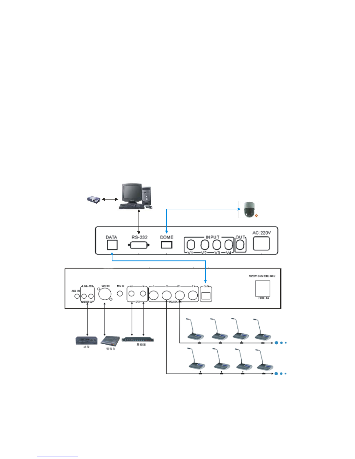
1. Dome port is used for connect Camera
2. There are three connectors of the camera A-G-B, and Dome port in the video
processor also have A-G-B connector, please connect each corresponding
connectors please use parallel connection way when connect more than one
camera.
3. the Data port is used for connect to the Data port on the conference system
main unit
Schematic diagram
Page 28
INTERPRETATION SYSTEM
Interpreter unit MC-303A
★ Designed by the latest digital technology in accordance with IEC914 and ISO.
★ Totally 7+1 channels, includes the original voice channel.
★ The system power supply for the interpreter unit is provided by main unit at 12V
safe voltage.
★ Unidirectional electret MIC and HIFI loud-speaker.
★ Voice adjustable and with prevention on feedback.
★ Digital display of the channels.
★ Equipped with a set of earphone.
★ Prevention on interpreter’s cough.
★ Frequency Response: 100-16000Hz
★ Sensitivity:-44±2dB
★ ON/OFF button on the microphone.
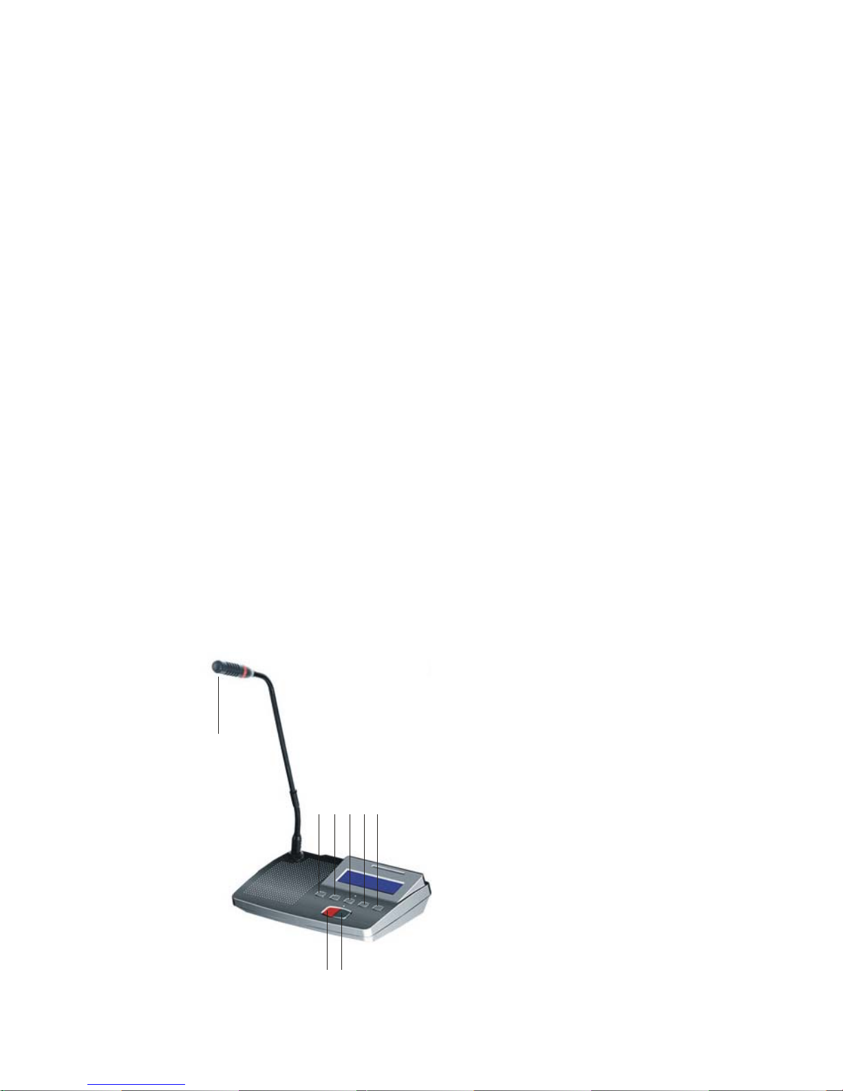
Schematic diagram of Interpreter unit
1.Transmit channel display
2.Transmit channel for choose, includes the original voice channel
3.Receiving channel display
4.Receiving channel for choose, includes the original voice channel
5.SLOW
6.On/Off button
7.Prevention on interpreter’s cough.
8.Annular red indicator lamp
1 2 3 4 5
6
7
8
Page 29
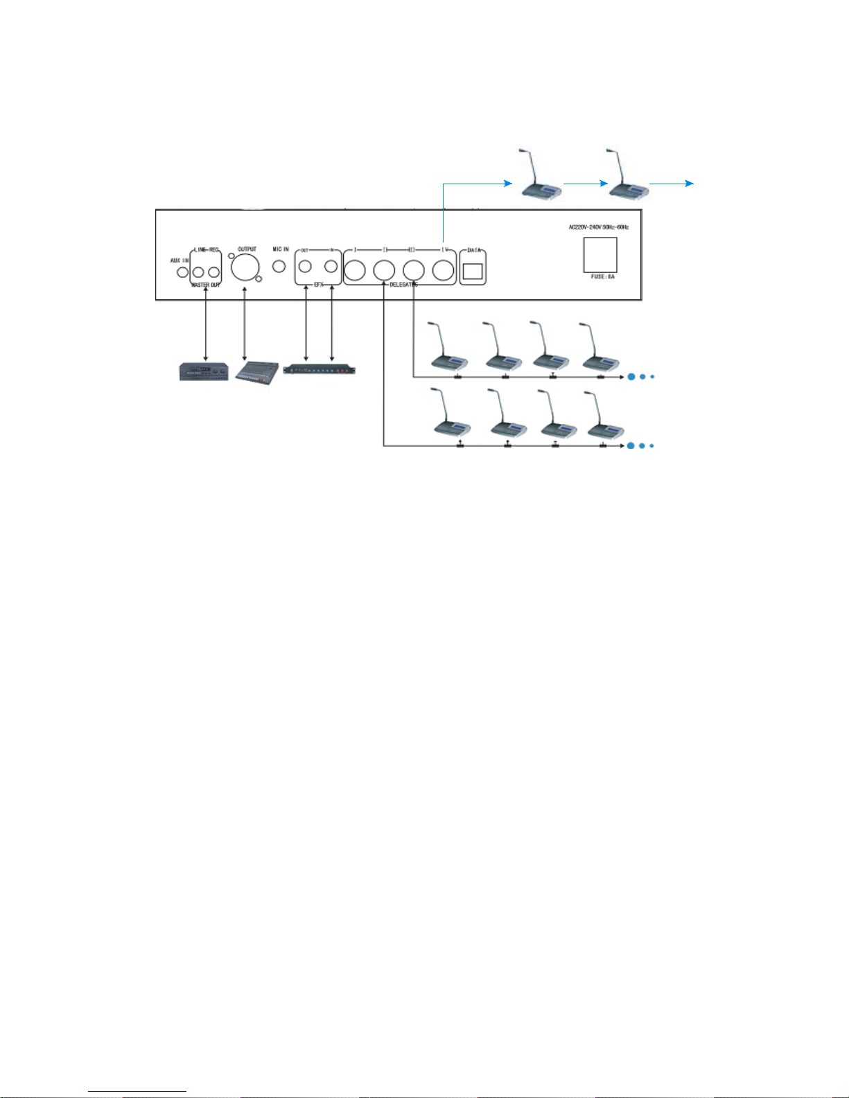
Schematic diagram
Interpreter unit
 Loading...