

Page 1

Technical Description of TANDBERG
8000 with software version E3/B8
TANDBERG
D12008 Rev. 11
Page 2

Technical Description of TANDBERG 8000 with software version E3/B8
Table of contents
1. INTRODUCTION............................................................................................................................................ 5
2. PRODUCT DESCRIPTION ........................................................................................................................... 7
2.1 CODEC ........................................................................................................................................................... 7
2.1.1 Software Versions..................................................................................................................................... 7
2.2 WIDE ANGLE VIEW (W.A.V.E.) CAMERA ...................................................................................................... 8
2.2.1 Camera Features ...................................................................................................................................... 8
2.2.2 Camera Pinouts and connectors............................................................................................................... 9
2.2.3 Multiple Camera Control ....................................................................................................................... 10
2.2.4 Camera Tracking.................................................................................................................................... 10
2.2.5 Calculation of Horizontal Viewing Area ................................................................................................ 11
2.2.6 Camera Control Interface....................................................................................................................... 11
2.3 REMOTE CONTROL....................................................................................................................................... 12
2.3.1 Transmission Protocol............................................................................................................................ 12
2.3.2 Key Pad Layout and Codes..................................................................................................................... 12
2.4 MONITORS ................................................................................................................................................... 13
2.4.1 Specifications TANDBERG 8000 monitors ............................................................................................ 13
2.5 STAND.......................................................................................................................................................... 14
2.6 TANDBERG NATURAL AUDIO MODULE (NAM II).................................................................................... 14
3. OPERATION AND USER INTERFACE ....................................................................................................15
4. CODEC INTERFACES................................................................................................................................. 16
4.1 NETWORK INTERFACES AND FEATURES....................................................................................................... 16
4.1.1 PRI E1/T1 ISDN & Leased Line E1/T1 Interface................................................................................... 17
4.1.1.1 PRI E1/T1 ISDN.............................................................................................................................................17
4.1.1.2 Leased Line E1/T1..........................................................................................................................................19
4.1.2 BRI ISDN Interface................................................................................................................................. 20
4.1.2.1 ISDN Subaddress & MSN..............................................................................................................................20
4.1.3 Ethernet / LAN Interface (H.323) ........................................................................................................... 21
4.1.3.1 Default IP Password .......................................................................................................................................21
4.1.3.2 Quality of Service features (QoS)...................................................................................................................21
4.1.3.3 Automatic selection of H.323 or H.320 outgoing calls...................................................................................22
4.1.3.4 IP adaptive bandwidth management ...............................................................................................................22
4.1.3.5 Gatekeeper authentication...............................................................................................................................22
4.1.3.6 Registration to Call Manager..........................................................................................................................22
4.1.3.7 Configuring an H.323 client on the CallManager 4.0 .....................................................................................23
4.1.3.8 H.323 ID.........................................................................................................................................................23
4.1.3.9 Dynamic playout buffering.............................................................................................................................23
4.1.3.10 Asymmetrical media capabilities....................................................................................................................23
4.1.3.11 Diagnostic tools for IP....................................................................................................................................23
4.1.3.12 NAT support...................................................................................................................................................24
4.1.3.13 Latency & Jitter ..............................................................................................................................................24
4.1.3.14 Layer 4 Ports used in H.323 calls ...................................................................................................................24
4.1.3.15 IP packet sizes ................................................................................................................................................25
4.1.3.16 Intelligent Packet Loss Recovery (IPLR) .......................................................................................................25
4.1.3.17 IP Conflict Warning........................................................................................................................................25
4.1.4 NET Interface ......................................................................................................................................... 26
4.1.5 Streaming................................................................................................................................................ 27
4.1.5.1 Automatic announcement of Streaming..........................................................................................................27
4.1.6 Intelligent Call Management (ICM) ....................................................................................................... 27
4.1.7 Network Profiles ..................................................................................................................................... 28
4.1.8 Encryption .............................................................................................................................................. 29
4.2 AGGREGATION STANDARDS......................................................................................................................... 30
4.2.1 BONDING .............................................................................................................................................. 30
4.2.2 H.221...................................................................................................................................................... 30
4.2.3 Encoding delay....................................................................................................................................... 30
4.3 DATA INTERFACE/APPLICATION PROGRAMMABLE INTERFACE (API) .......................................................... 31
4.3.1 Data Protocols........................................................................................................................................ 32
4.3.2 Translation in RS232 cable for TANDBERG 8000 dual monitor........................................................... 33
4.4 VIDEO INTERFACES AND SPECIAL VIDEO FEATURES.................................................................................... 34
4.4.1 Video Inputs............................................................................................................................................ 34
4.4.2 XGA Input (‘PC Presenter’) ................................................................................................................... 34
D12008 Rev. 11 2
Page 3

Technical Description of TANDBERG 8000 with software version E3/B8
4.4.2.1 VGA, SVGA and XGA Pin layout .................................................................................................................35
4.4.3 PC Soft Presenter ................................................................................................................................... 35
4.4.4 Video Outputs......................................................................................................................................... 36
4.4.5 XGA Output ............................................................................................................................................ 36
4.4.6 Optimized Video Compression ............................................................................................................... 37
4.4.7 Intelligent Video Management (IVM)..................................................................................................... 37
4.4.7.1 IVM Resolution..............................................................................................................................................38
4.4.8 Duo Video............................................................................................................................................... 38
4.4.9 Digital Clarity......................................................................................................................................... 40
4.4.10 Natural Video (iCIF/iSIF).................................................................................................................. 40
4.4.11 Native Resolutions ............................................................................................................................. 40
4.4.12 One-touch Snapshot........................................................................................................................... 41
4.4.13 Screen Saver ...................................................................................................................................... 41
4.5 AUDIO INTERFACES AND SPECIAL AUDIO FEATURES ................................................................................... 42
4.5.1 Audio Inputs............................................................................................................................................ 42
4.5.1.1 Specification microphone Inputs ....................................................................................................................42
4.5.1.2 Specification audio line Inputs .......................................................................................................................43
4.5.1.3 Specification standard microphone (AT841R) ...............................................................................................43
4.5.1.4 Specification Audio Science microphone (Optional Equipment) ...................................................................44
4.5.2 Audio Outputs......................................................................................................................................... 44
4.5.2.1 Specification Audio line Outputs....................................................................................................................45
4.5.3 Flexible Audio Features ......................................................................................................................... 45
4.5.4 Acoustic Echo Cancellers....................................................................................................................... 46
4.5.4.1 Adjusting the Acoustic Echo Cancellers.........................................................................................................46
4.5.5 Noise Reduction (NR) ............................................................................................................................. 47
4.5.6 Audio levelling/ Automatic Gain Control (AGC).................................................................................... 47
4.5.7 VCR Audio Features............................................................................................................................... 48
4.5.8 Telephony ............................................................................................................................................... 48
4.5.9 Analogue Telephone add-on (US option only)........................................................................................ 48
4.5.10 Microphone Off.................................................................................................................................. 48
4.5.11 Audio Compression Algorithms ......................................................................................................... 49
4.6 SYSTEM MANAGEMENT ............................................................................................................................... 50
4.6.1 LAN Interface Set-up .............................................................................................................................. 50
4.6.2 Platform Requirements ........................................................................................................................... 51
4.6.3 Protocols Supported ............................................................................................................................... 51
4.6.4 System Management Functionality......................................................................................................... 52
4.6.4.1 Remote software upgrades using FTP: ...........................................................................................................52
4.6.4.2 Remote software upgrades during a call.........................................................................................................52
4.6.4.3 Management using a standard Web-browser:.................................................................................................52
4.6.4.4 Management using a standard Telnet-client: ..................................................................................................52
4.6.4.5 Management using a terminal connected to the RS232 port:..........................................................................52
4.6.4.6 Remote Management using SNMP:................................................................................................................53
4.6.5 Security................................................................................................................................................... 53
4.6.5.1 Disable Services .............................................................................................................................................53
4.6.5.2 Security Alert..................................................................................................................................................53
4.6.6 System Protection ................................................................................................................................... 53
4.6.6.1 System Access (/Account) codes....................................................................................................................53
4.6.6.2 Menu Password...............................................................................................................................................54
4.6.6.3 Authentication of Remote Management System.............................................................................................54
4.6.7 Layer 4 ports used by the system ............................................................................................................ 54
4.7 WEB SNAPSHOTS.......................................................................................................................................... 56
4.8 TANDBERG MULTISITE ............................................................................................................................ 56
4.8.1 MultiSite Cascading ............................................................................................................................... 59
5. MISCELLANEOUS FEATURES................................................................................................................. 60
5.1 MULTI-LANGUAGE OPTIONS ........................................................................................................................ 60
5.2 DIRECTORY .................................................................................................................................................. 60
5.2.1 MultiSite Entries..................................................................................................................................... 60
5.3 BOOT UP LOGO ............................................................................................................................................. 61
5.4 STARTUP SCRIPTS......................................................................................................................................... 61
5.5 LOOPBACK TESTING FOR REMOTE DIAGNOSTICS......................................................................................... 61
5.6 MAXIMUM CALL LENGTH ............................................................................................................................. 62
5.7 CLOSED CAPTIONING/TEXT CHAT ............................................................................................................... 62
5.8 OTHER STANDARDS SUPPORTED .................................................................................................................. 62
5.8.1 H.320...................................................................................................................................................... 62
5.8.2 H.323...................................................................................................................................................... 62
5.8.3 H.331 (Broadcast mode)......................................................................................................................... 62
D12008 Rev. 11 3
Page 4

Technical Description of TANDBERG 8000 with software version E3/B8
5.8.4 H.231/H.243 (MCU control) .................................................................................................................. 63
5.8.5 H.243 Password...................................................................................................................................... 63
5.8.6 H.281 (FECC) ........................................................................................................................................ 63
5.8.7 KG-194/KIV-7 (NATO encryption)......................................................................................................... 63
6. ENVIRONMENTAL ISSUES....................................................................................................................... 64
6.1 TANDBERG’S ENVIRONMENTAL POLICY................................................................................................... 64
6.2 ENVIRONMENTAL CONSIDERATIONS.......................................................................................................... 64
7. PRODUCT APPROVALS............................................................................................................................. 65
7.1 CONNECTION OF TELE-TERMINAL EQUIPMENT ............................................................................................ 65
7.2 EMC EMISSION - RADIATED ELECTROMAGNETIC INTERFERENCE ............................................................... 65
7.3 EMC IMMUNITY........................................................................................................................................... 65
7.4 ELECTRICAL SAFETY.................................................................................................................................... 65
8. PRODUCT RELIABILITY .......................................................................................................................... 65
9. TECHNICAL SPECIFICATION OF TANDBERG 8000.......................................................................... 66
9.1 MECHANICAL INFORMATION ........................................................................................................................ 66
9.2 PACKAGING.................................................................................................................................................. 67
9.2.1 TANDBERG 8000 parcels ...................................................................................................................... 67
9.3 OPERATING TEMPERATURE AND HUMIDITY................................................................................................. 67
9.4 STORAGE AND TRANSPORT TEMPERATURE .................................................................................................. 67
9.5 SYSTEM POWER CONSUMPTION ................................................................................................................... 67
10. TECHNICAL SPECIFICATION SHEET.............................................................................................. 68
D12008 Rev. 11 4
Page 5

Technical Description of TANDBERG 8000 with software version E3/B8
1. Introduction
The TANDBERG 8000 is truly a combination of aesthetics and superior technology using two
wide screen 50” plasma monitors. It is a videoconferencing system designed for use with
network rates from 56 kbps up to 2 Mbps, using ITU-T H.320 standards for video compression
and a combination of H.221 and BONDING for communication on up to 30 ISDN B-channels.
The system also support calls up to 3 Mbps when connected to a LAN, using the ITU-T H.323
standard. All features of the TANDBERG 8000 are based on standards set by the ITU-T.
• When directly connected to BRI ISDN networks, TANDBERG's SoftMux enables
BONDING calls up to 768 kbps.
• When directly connected to PRI ISDN networks, TANDBERG's SoftMux enables
BONDING calls up to 2 Mbps.
• When directly connected to special data networks, TANDBERG's network manager
enables automatic detection of speeds up to 2 Mbps.
• When directly connected to a Local Area Network, TANDBERG's network manager
enables automatic detection of speeds up to 3 Mbps.
If the system is connected to both ISDN and LAN the TANDBERG 8000 can handle both ISDN
sites and IP sites in the same call.
D12008 Rev. 11 5
Page 6
Technical Description of TANDBERG 8000 with software version E3/B8
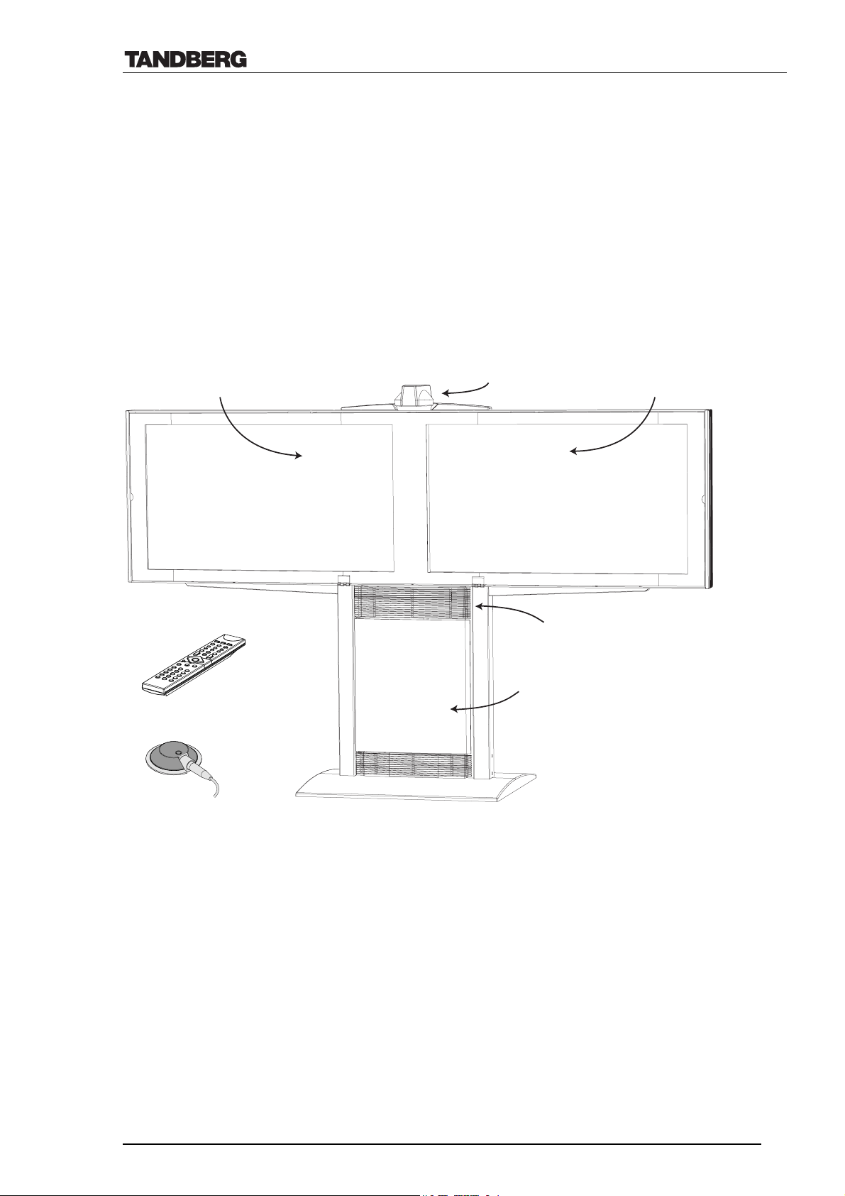
The TANDBERG 8000 videoconferencing system consists of a Codec (COding / DECoding
unit), combined with two PAL or NTSC monitors, a remotely controllable PAL or NTSC
camera, the TANDBERG Natural Audio Module, a hand held remote control unit, a tabletop
microphone and a single stand; consisting of the Base & the Monitor Rack. The TANDBERG
8000 is installed as a dual monitor system as shown below.
The Codec and Natural Audio Module are installed inside the Base while the plasma monitor(s)
are installed inside the Monitor Rack.
main monitor
W.A.V.E. camera
2nd (dual) monitor
Remote Control
Microphone
Natural Audio Module
Codec
D12008 Rev. 11 6
Page 7
Technical Description of TANDBERG 8000 with software version E3/B8
2. Product Description
2.1 Codec
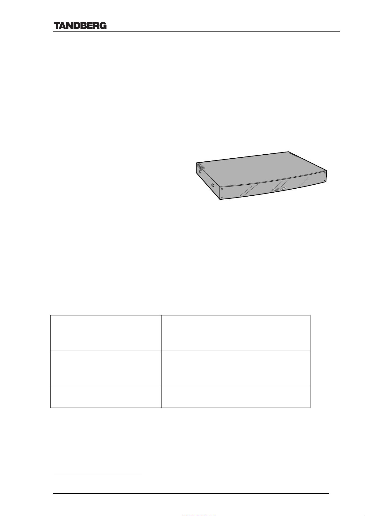
The Codec1 is the "brain" of the system and handles all incoming and outgoing video, audio and
data towards the switched public telephone networks, Local Area Networks (LAN) or external
networks.
The Codec receives pictures from a video source e.g. the TANDBERG Camera, encodes and
compresses the live video and audio at rates of up to 30 frames per second (60 fields per
second). The coded image and audio is transmitted to a remote unit at rates up to 768 kbps
(ISDN BRI), 2 Mbps (ISDN PRI/IP networks/External networks) or 3 Mbps (IP networks).
The Codec also receives incoming video
and audio at rates up to 3 Mbps, decodes the
live video and audio and passes the video
signal to the monitor for display. Audio is
decoded and passed to the TANDBERG
Natural Audio module.
2.1.1 Software Versions
There is one software version for TANDBERG 8000; available in either PAL or NTSC. The
software allows for calls up to:
• 768 kbps on ISDN BRI
• 2 Mbps on ISDN PRI/E1 (1.5 Mbps on ISDN PRI/T1)
• 2 Mbps on External Networks
• 3 Mbps on IP networks
The software includes all the following features:
Natural Presenter Package (NPP)
• Duo Video
• Full Digital Clarity (Transmit&Receive)
2
(4xCIF/4xSIF/VGA/SVGA/XGA
)
• PC Soft Presenter
MultiSite (MS)
• NPP
• Internal MCU
• Audio Bridge
Security
• DES (56 bit key) and AES (128 bit key)
Encryption
1
TANDBERG Codec 6000 is used in the TANDBERG 8000 system
2
XGA only supported from software E1 onwards
D12008 Rev. 11 7
Page 8
Technical Description of TANDBERG 8000 with software version E3/B8
2.2 Wide Angle View (W.A.V.E.) Camera
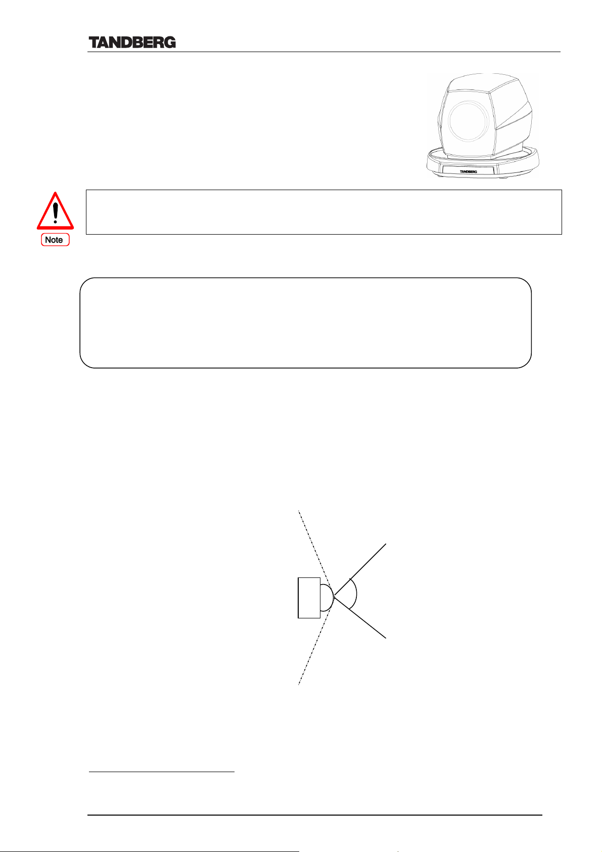
The TANDBERG 8000 is equipped with the W.A.V.E. Camera,
which is controlled by the remote control. This allows the user to
zoom, focus, pan and tilt the camera. The camera is either PAL or
NTSC depending on the country of use.
The power on the codec must be switched off whenever connecting/disconnecting a camera
to/from the codec or a ‘daisy chain’3. Only cameras with software revision TT0a or later support
camera tracking and daisy chaining.
2.2.1 Camera Features
Camera Specifications 1/3” CCD Colour Camera (single chip) PAL or NTSC
190° Pan+77° Horizontal Field of View 10 x Zoom (optical)
35° Tilt +61° Vertical Field of View 15 Camera Pre-sets
Auto/Manual Focus/Brightness/White Balance Min. illumination 2.0 Lux (F1.8 wide)
Max camera cable length supported 10m (32,8 ft) Focal length f=4,2 mm to 42 mm
Power reqmnts DC 12 V, min. 1Amps ±5% Aperture F=1,8 to 2,7 (wide to tele)
Max. focus response time 0.5sec (∞ to near) Zoom speed wide to tele 1,8sec
• The system is able to store up to 15 pre-set camera positions, making it easier for the user to
change the selected view rapidly during a presentation or a meeting. If the main camera is
selected, pan, tilt, zoom and focus will also be stored with the preset. The first 10 presets may
be accessed via the remote control, while the 5 remaining presets are accessed by data port
commands or IR-codes (e.g. by using the TANDBERG Tracker4).
• The camera is equipped with a wide angle lens and covers a wide area as shown below:
The camera covers a horizontal field of view of 77°, while panning takes the range up close
5
to 270°
• Minimum horizontal field of view (maximum zoom in) is 7.7°.
• The camera covers a vertical field of view of 61°, while tilting takes the range up to 96°.
• Tilting the camera max. 15° upward and max. 20° downward.
• Automatic or manual brightness, focus and white balance ensures that the user obtains the
best possible picture.
.
267° field of view
Camera seen
from above
77° field of view
3
See chapter 2.2.2 for Multiple W.A.V.E. camera support
4
Information of the TANDBERG Tracker is found in the User Manual.
5
Maximum wide angle for all camera measurements.
D12008 Rev. 11 8
Page 9
Technical Description of TANDBERG 8000 with software version E3/B8
• Horizontal resolution: 450 TV lines for PAL and 460 TV lines for NTSC.
• Number of picture elements: 752 (h) x 582 (v) for PAL and 768 (h) x 494 (v) for NTSC.
• Shortest Subject Distance: 10 mm (wide end) and 1000 mm (tele end)
• At the codec’s side, the camera cable splits in two: One presents the S-video Output (for
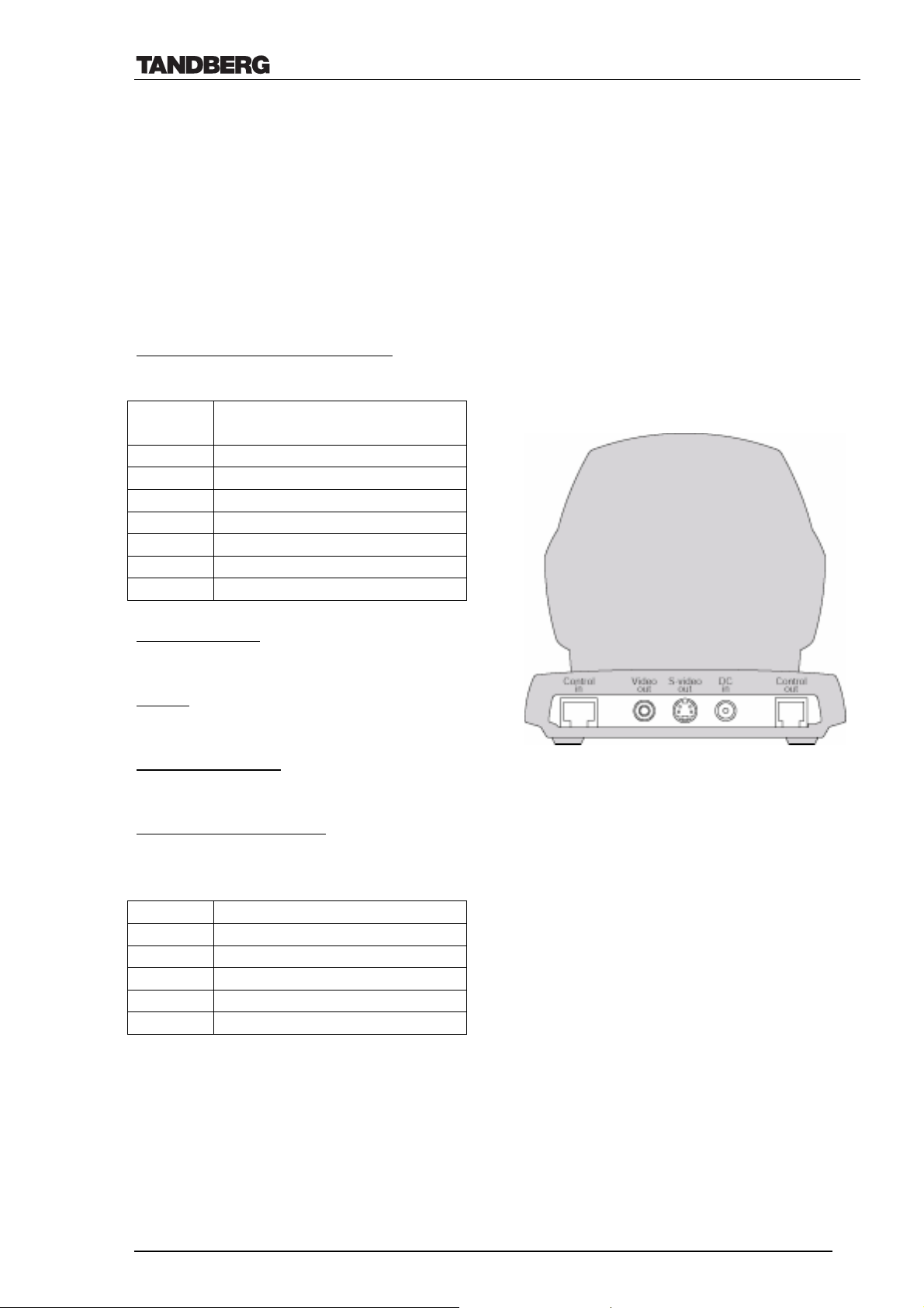
connection to codec’s Video Input1) while the other 9-PIN D-sub connector presents power
(12V) and control signals for moving the camera.
• The maximum length of the camera cable for main camera supported by TANDBERG is 10m
(33 ft)- may be extended up to 20 m (66 ft) when using cable with external power supply.
2.2.2 Camera Pinouts and connectors
8-PIN RJ (shielded modular jack):
This connector is used for the power and control signals to the main camera.
pin-8 +12 V (presence when
connected in daisy chain)
pin-7 GND
pin-6 GND
pin-5 RXD (in)
pin-4 TXD (out)
pin-3 +12V
pin-2 GND
pin-1 +12V
Standard Phono:
Used for composite video signal
Power:
2.0 mm DC power jack (+12V, 1A required)
Standard Mini Din:
Used for S-Video signal
6-PIN RJ (modular jack):
This connector is used when cascading cameras: Control (out) signal and external camera
detection. Note: It does not provide power for cascaded camera.
Pin 6 GND
Pin 5 GND
Pin 4 RXD (in)
Pin 3 TXD (out)
Pin 2 Presence (+12V in daisy chain)
Pin 1 GND
D12008 Rev. 11 9
Page 10
Technical Description of TANDBERG 8000 with software version E3/B8
2.2.3 Multiple Camera Control
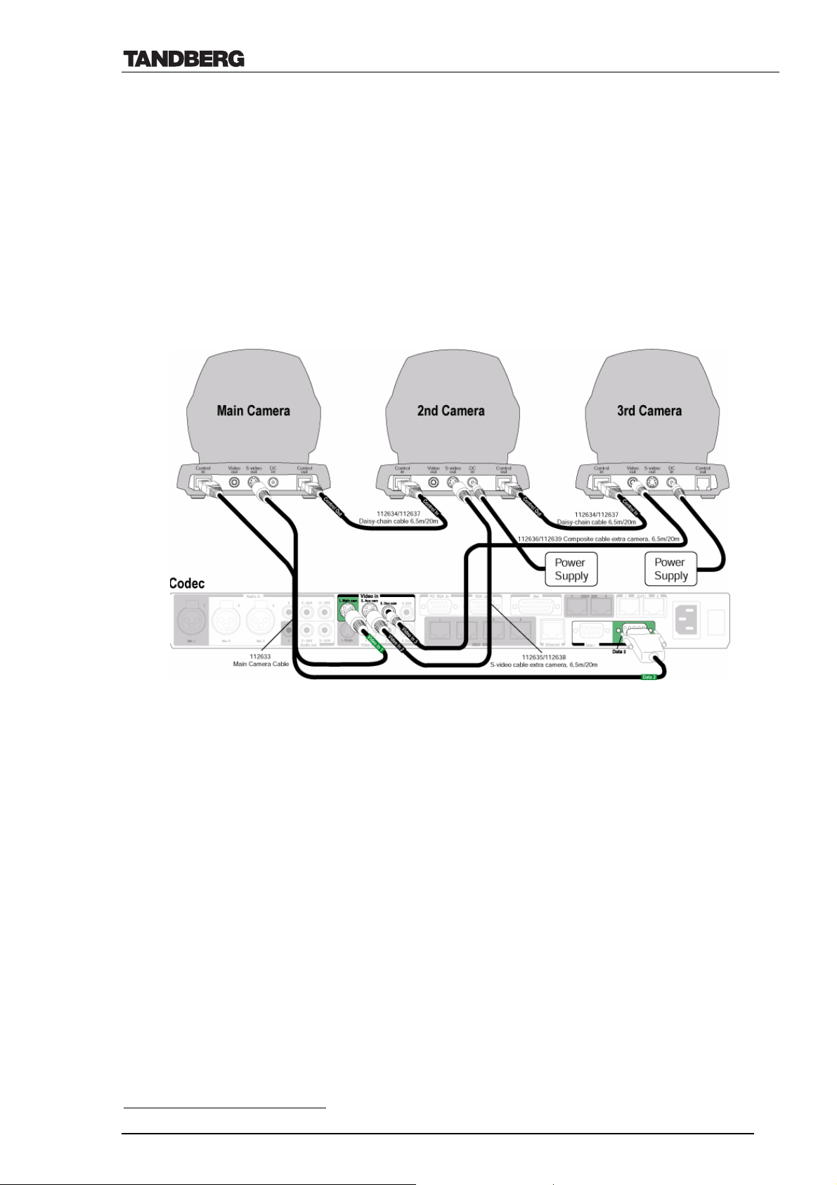
The TANDBERG 8000 is able to control up to four W.A.V.E. cameras from the remote control.
The Main Camera must be connected to data port 2 on the Codec. The other cameras must be
daisy-chained to the Main Camera. The Codec will provide power for the Main Camera only.
The other cameras each need a separate power supply. The Main Camera must be connected to
Video Input 1; the second camera must be connected to Video Input 2 and so on.
The codec will automatically detect the number of cameras and the camera ID can be read in the
‘System self test’ menu. The maximum length of the camera cable for multiple cameras
supported by TANDBERG is 20 m (65 ft).
The figure below is an example of how multiple cameras should be connected:
2.2.4 Camera Tracking
Voice-activated camera tracking with noise suppression and preset-combination has been
implemented in the TANDBERG 8000 software. A W.A.V.E. Camera connected to Video Input
1 can be used for camera tracking6. Two or three microphones must be installed and each
microphone must be associated with a camera-preset position (preset P7 to Mic1, P8 to Mic2
and/or P9 to Mic3). Camera tracking is temporarily turned off when another video source is
selected (e.g. a document camera) or when the camera is manually adjusted.
6
If more than one W.A.V.E. camera is connected to the system, the presets may also be put on these cameras.
D12008 Rev. 11 10
Page 11
Technical Description of TANDBERG 8000 with software version E3/B8
2.2.5 Calculation of Horizontal Viewing Area
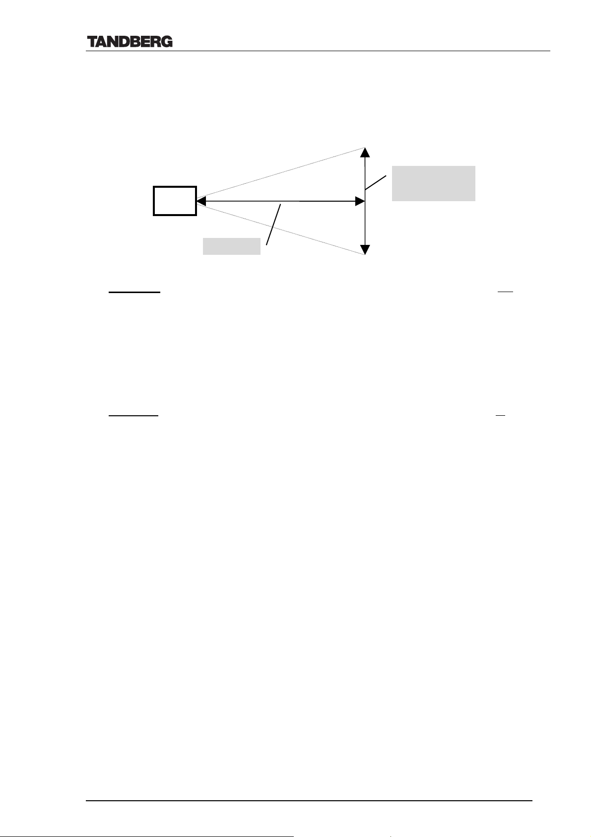
The W.A.V.E. Camera’s viewing area is maximized when the camera is zoomed fully out and
minimized when the camera is zoomed fully in. To calculate the viewing area, the following
measurements need to be taken:
Camera
Horizontal
Viewing Area B
Distance A
The maximum viewing area for the W.A.V.E. camera, with the camera zoomed fully out is
calculated by the formula:
(Distance) A x 1.6 = (Max. viewing width) B
max
E.g. If A is 5 meters then the width of the viewing area B will be 5 x 1.6 = 8.0 meters
The minimum viewing area for the W.A.V.E. camera, with the camera zoomed fully in is
calculated by the formula:
(Distance) A x 0.13 = (Min. viewing width) B
min
E.g. If A is 5 meters then the width of the viewing area B will be 5 x 0.13 = 0.65 meters
2.2.6 Camera Control Interface
The control cable for the camera must be connected to Data port 2. When the Codec is powered
up, Data port 2 will automatically detect if a camera is attached to it.
The TANDBERG 8000 supports two different camera protocols, the TANDBERG camera
protocol and the VISCA protocol. To control the W.A.V.E. Camera, the following parameters
are required on Data port 2:
• 9600 Baud
• 8 data bits
• 1 stop bit
• No parity
• Auto or VISCA
TANDBERG 8000 also supports:
• Cameras such as Sony EVI D30/31 using the Sony VISCA protocol.
The camera type in use will be automatically detected in the system boot-sequence except
cameras using the VISCA protocol, where this option must be selected in the data port menu.
D12008 Rev. 11 11
Page 12
Technical Description of TANDBERG 8000 with software version E3/B8
2.3 Remote Control
2.3.1 Transmission Protocol
The Infra Red (IR) sensor for the remote control is located in front of
the W.A.V.E. Camera, just below the front glass. There is also a
second IR-sensor located in the front of the Codec itself, which will
be automatically enabled if the W.A.V.E. Camera is not connected to
Data port 2. The TANDBERG handheld remote control transmits IRsignals using the following parameters:
Protocol Siemens SDA2208
Reference Freq. 485 kHz
Address 4 & 7
IR wavelength 940 nm
IR carrier Freq. 30 kHz
2.3.2 Key Pad Layout and Codes
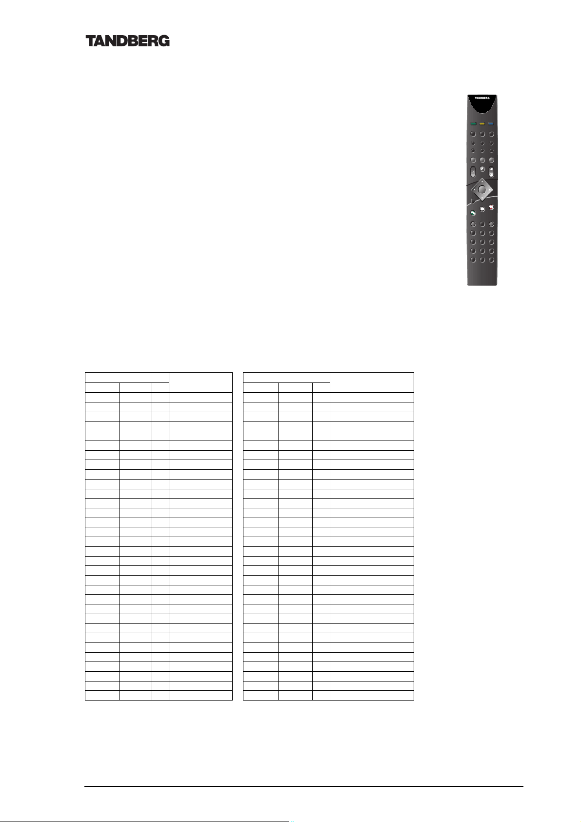
The hand held remote control transmits 46 different codes. The
keypad will not transmit additional codes if more than one key is
pressed simultaneously.
The following table shows relationship between the remote’s buttons
and their respective codes.
BUTTON CODES REMOTE BUTTON CODES REMOTE
Address Decimal Hex BUTTON NAME Address Decimal Hex BUTTON NAME
4 1 01 NUMBER 1 4 33 21 OK
4 2 02 NUMBER 2 4 34 22 CONNECT(GREEN)
4 3 03 NUMBER 3 4 35 23 DISCONNECT (RED)
4 4 04 NUMBER 4 4 36 24 DIRECTORY
4 5 05 NUMBER 5 4 37 25 MENU
4 6 06 NUMBER 6 4 38 26 DELETE
4 7 07 NUMBER 7 4 39 27 STORE
4 8 08 NUMBER 8 4 40 28 PRESET
4 9 09 NUMBER 9 4 41 29
4 10 0A NUMBER 0 4 42 2A
4 11 0B * 4 43 2B SCREEN MENU A (LEFT)
4 12 0C # 4 44 2C SCREEN MENU B (MIDDLE)
4 13 0D MAIN CAM 4 45 2D SCREEN MENU C (RIGHT)
4 14 0E AUX 4 46 2E
4 15 0F DOC 4 47 2F
4 16 10 VCR 4 48 30 P1
4 17 11 PC 4 49 31 P2
4 18 12 SELFVIEW 4 50 32 P3
4 19 13 SNAPSHOT 4 51 33
4 20 14 FAR END 4 52 34
4 21 15 PIP MOVE 4 53 35
4 22 16 ZOOM OUT 4 54 36
4 23 17 ZOOM IN 4 55 37
4 24 18 4 56 38
4 25 19 VOLUME DOWN 4 57 39
4 26 1A VOLUME UP 4 58 3A
4 27 1B MIC OFF 4 59 3B
4 28 1C 4 60 3C
4 29 1D UP 4 61 3D
4 30 1E DOWN 4 62 3E
4 31 1F LEFT 4 63 3F TOUCH DET ECT
4 32 20 RIGHT 7 25 19 LOW BATT
P1P3P
2
aux doc cammain cam
vcr
snapshotpc
move pip
selfviewfar end
mic off
+
zoom
-
OK
u
n
e
m
t
c
e
n
n
o
c
s
i
d
y
r
o
t
c
e
r
i
d
t
c
e
n
n
o
c
storepresetsdelete
P
abc
def
32
1
jklghi
mno
4
5
wxyztuvpqrs
7
968
#
0
*
D12008 Rev. 11 12
Page 13

Technical Description of TANDBERG 8000 with software version E3/B8
2.4 Monitors
The TANDBERG 8000 is supplied with either PAL or NTSC
plasma monitors depending on the country of use, both
supporting up to XGA resolution. The monitors are placed
side by side inside the Monitor Rack.
2.4.1 Specifications TANDBERG 8000 monitors
Specifications7:
Screen size 50” diagonal
Aspect ratio 16:9 or 4:3
Number of pixels 1280 H / 768 V (16:9) or 1024 H / 768 V (4:3)
View angle Horizontal/Vertical 160 x 160 degrees
TV standard PAL, NTSC, Composite, Y/C, RGB, VGA,
SVGA, XGA
Inputs Analogue RGB (G on synch) / Composite / S-
Video / RS-232C / D-sub 15 (HD compatible)
7
See ch.9 for mechanical specifications
D12008 Rev. 11 13
Page 14

Technical Description of TANDBERG 8000 with software version E3/B8
2.5 Stand
TANDBERG 8000 stand consists of the Base and the Monitor Rack, both with a removable rear
panel8.
The Natural Audio Module and the Codec are located inside the base. The Codec’s connections
are easily accessible once the front door of the Base has been opened.
To place the monitor(s) inside the Monitor Rack, the large one-piece plastic front-cover must be
opened.
The cables that need to go out from the system (e.g. ISDN cables, power cables) can be routed
through a hole at the back of the Base. To install/add cables going out of the system through this
hole, the rear panel of the Base needs to be opened.
2.6 TANDBERG Natural Audio Module (NAM II)
The NAM II is a specially designed TANDBERG audio module that provides the user with
unique audio qualities.
The Natural Audio Module II consists of the following:
Three way active speaker system with active crossover
• 2 x 130mm bass speaker elements
• 1 x 25mm tweeter
Audio amplifier9: 3 x 50 Watts
The Natural Audio Module is placed inside the Base of the system.
8
To remove the rear panel(s), a phillips/starshaped screwdriver is needed.
9
The Amplifier has a power selector for 230V or 115V operation which includes a fuse.
D12008 Rev. 11 14
Page 15
Technical Description of TANDBERG 8000 with software version E3/B8
3. Operation and User Interface
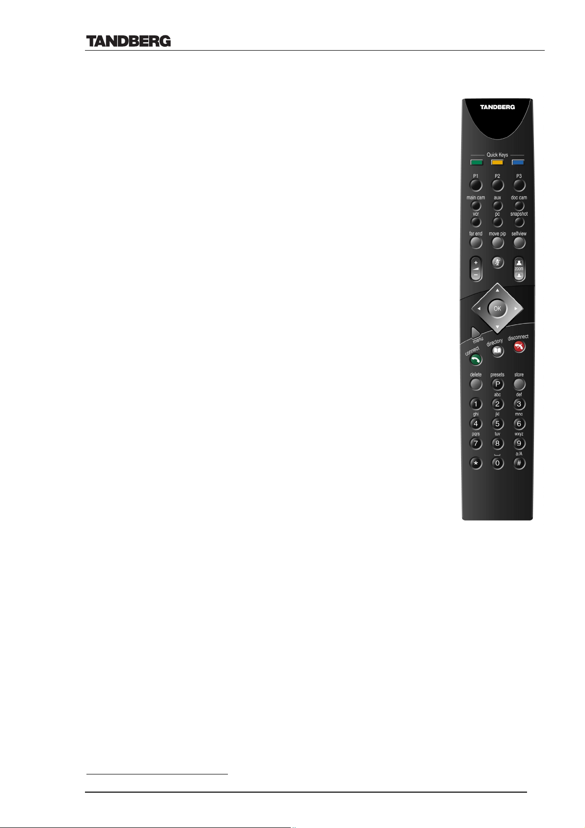
The TANDBERG 8000 is normally operated via a hand-held, infrared
remote control. TANDBERG 8000's simple and concise multi-coloured
on-screen menu ensures that the user will be guided directly to the option
or the feature required. The menu system is cursor driven and easy to use.
With the intelligent on-screen user feedback the system always ensures the
relevant information is given to the user. (E.g. if a channel is lost, the user
will see on-screen text message ‘please wait, re-establishing the call’).
The Quick Keys (located on the top of the remote) relate to the three
blocks
at the bottom of the screen. The text on these blocks will change depending
on which menu is selected.
The user will hear a key tone when entering letters and digits via the
remote control. The key tones may be turned off via the system’s data port
if desired.
The TANDBERG 8000 can also be controlled via the data port of the
Codec by using a comprehensive set of data port commands10. This
enables the Codec to be controlled by a different user interface, such as an
AMX or Crestron system.
The web browser can be used as another interface to the TANDBERG
8000. By connecting the codec to a LAN, the codec may be accessed from
a PC located on the same LAN or WAN; allowing the codec’s features to
be controlled remotely via the web interface.
For information on how to operate the system, please see the
‘TANDBERG 8000 User Manual’ supplied with the system.
10
Please, refer to ‘TANDBERG API – (Dataport User Guide)’ (D11943)
D12008 Rev. 11 15
Page 16
Technical Description of TANDBERG 8000 with software version E3/B8
4. Codec Interfaces
Extensive use of industry standard interfaces and connectors ensure effortless integration of
external equipment with the TANDBERG 8000. These interfaces can easily be controlled via
one of the intuitive user interfaces. The TANDBERG 6000 codec is used in the TANDBERG
8000 system.
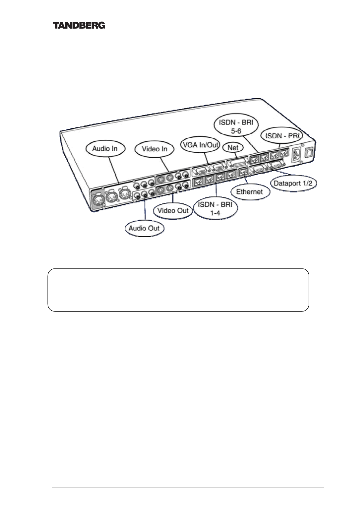
4.1 Network Interfaces and Features
Network Interfaces 1 x PRI (RJ-45 Jack) Primary Rate & Leased Line E1/T1 (G.703) Interface up to 2 Mbps
1 x PRI (RJ-45 Jack) Primary Rate (for cascading)
6 x ISDN I.420 (RJ-45 Jack) Basic Rate Interface S/T (2B+D) up to 768 kbps
1 x X.21 / V.35 / RS449 with 1 x RS366 Call Control up to 2 Mbps
1 x Ethernet (RJ-45 Jack) LAN interface (10/100 Mb) up to 3 Mbps
The TANDBERG 8000 can easily switch between the different networks ‘on-the-fly’, via the
user interface. The Codec does not need to reboot after changing the network. The supported
networks are:
• 1 PRI (RJ-45 jack) Primary rate interface & Leased Line E1/T1 (G.703) interface for
transmission speeds from 56 kbps to 2 Mbps.
• 1 PRI (RJ-45 jack) Primary rate interface for transmission speeds from 56 kbps to 2 Mbps
(for cascading to other ISDN terminals).
• 6 x BRI ISDN I.420 (RJ-45 jack) Basic rate interface S/T (2B+D) for up to 768 kbps.
• 1 x X.21 or V.35 / RS449 with RS366 call control for special applications or leased line
networks for transmission speeds up to 2 Mbps with automatic detection of bit rates.
• 1 x Ethernet (RJ-45 jack) Local Area Network interface (10/100 Mb) for transmission speeds
up to 3 Mbps.
D12008 Rev. 11 16
Page 17

Technical Description of TANDBERG 8000 with software version E3/B8
4.1.1 PRI E1/T1 ISDN & Leased Line E1/T1 Interface
The main RJ-45 jack supports bit rates from 56 kpbs up to 2 Mbps (1.5 Mbps PRI/T1) and may
be used as a PRI E1/T1 interface or a Leased Line E1/T1 interface. Port number 2 is designed
for cascading features when PRI is used.
4.1.1.1 PRI E1/T1 ISDN
Both the Intelligent Call Management (ch. 4.1.6) and the call status are implemented for PRI.
The PRI interface may require an external CSU depending on the network layout. ‘Cable
Length’ in the PRI set-up menu specifies the distance from the Codec to the CSU or last
repeater.
A CSU should not be required if the system is within 200 m (655 ft) of the last repeater
depending on the PRI cable quality.
The TANDBERG 8000 supports the PRI protocols AT&T Custom, National ISDN and ETSI
(Euro ISDN). Within these protocols the following switches are supported:
Switches Protocols supported
4ESS (AT&T) AT&T Custom
5ESS (AT&T) AT&T Custom and National ISDN11
DMS250 (Nortel) National ISDN
DMS100 (Nortel) National ISDN
(any switch) ETSI (Euro ISDN)
When booting up with PRI selected, the boot-up text will display ‘Waiting for network
activation’. The boot-up text will not be removed until the PRI line is active or a remote control
button is pressed.
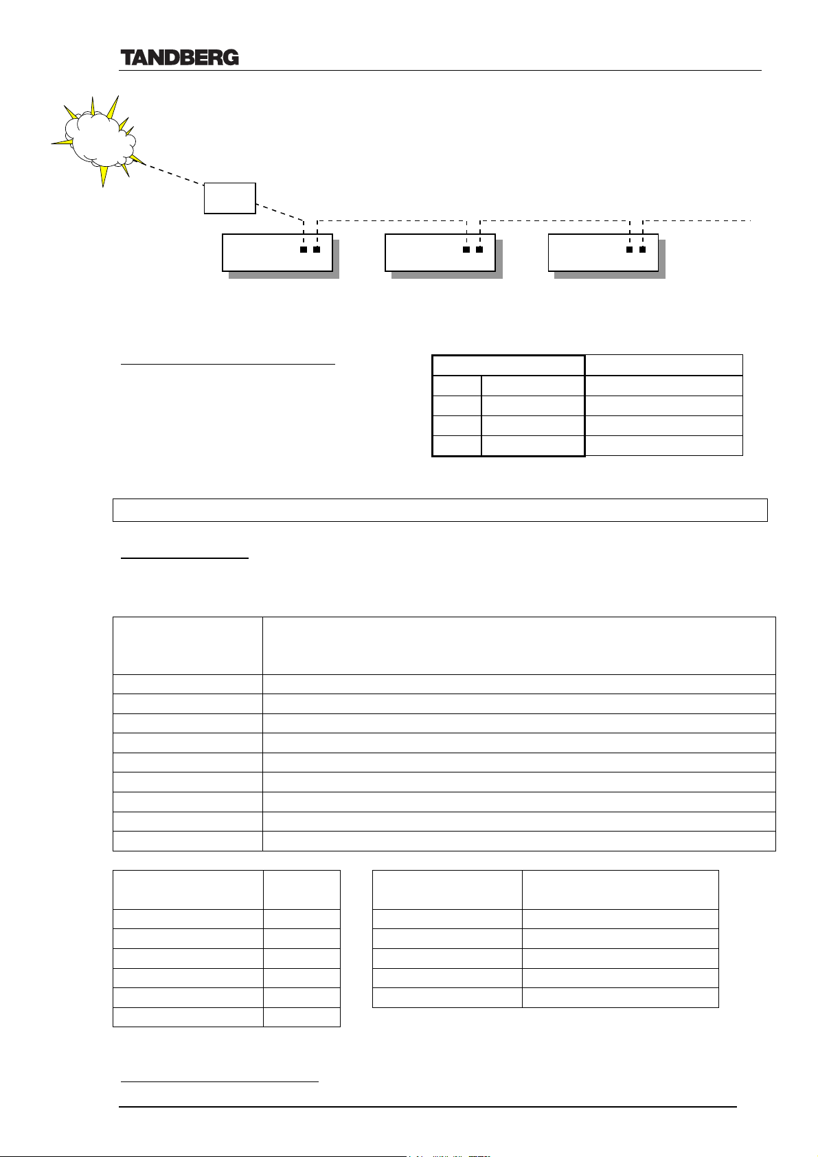
Several TANDBERG 8000 (i.e. 6000 codecs) can be connected to the second PRI port on the
TANDBERG 8000 by cascading. Calling systems on the same PRI port is easily done through
MSN.
Channel hunting is provided for outgoing calls, this feature is normally used when the number
of channels needs to be specified and when a National ISDN PRI is used with a nonTANDBERG PRI unit in the cascading chain. The channels outside low and high can then be
reserved by other devices. When no value is specified for low or high channel, they default to 1
(low), 23 (high US) and 30 (high Europe). Default search is from high to low.
11
Dependent on the configuration of the switch
D12008 Rev. 11 17
Page 18
Technical Description of TANDBERG 8000 with software version E3/B8
Cascading TANDBERG 6000 codecs
ISDN
Your PRI line
Line Numbe rs
….7610
….7611
….7612
…..etc.
…..
…..
CSU or
NT
Codec 6000
Codec # 1
PRI 1
….7610
MSN ON
PRI 2
PRI 1 PRI 2
Codec 6000
Codec # 2
….7611
MSN ON
PRI 1 PRI 2
Codec 6000
Codec # 3
….7612
MSN ON
….etc……
Pinout of PRI E1/T1 Interface:12
Cascading codecs requires a PRI crossover
PRI Pinout Crossover PRI cable
1 TIP RX 4
2 RING RX 5
4 RING TX 1
5 TIP TX 2
cable, wired as described above.
NOTE: TANDBERG recommends always using category 5 cabling.
PRI T1 (US only):
Network Service Facility (NSF) can be configured as blank/no value (i.e. NSF not used –
default) or any value between 0 and 31, to describe the service facility on the PRI/T1 line.
AT&T
Service code
Service
(ref.1)
0 Disable
1 SDN (Including GSDN)
2 Toll Free Megacom (800)
3 Megacom
6 ACCUNET Switched Digital Service (incl. Switched Digital International)
7 Long Distance Service (incl. AT&T World Connect)
8 International Toll Free Service (1800)
16 AT&T MultiQuest
23 Call Redirection Service
Sprint
Service code (ref.2) Service
MCI
Service code (ref.2) Service
0 Reserved 1 VNET/Vision
1 Private 2 800
2 Inwatts 3 PRISM1, PRISMII, WATS
3 Outwatts 4 900
4 FX 5 DAL
5 TieTrunk
Ref. 1: AT&T TR 41459 Specification, June 1999, page 76
Ref. 2: Ascend Multiband Plus-T1/PRI, User Documentation, Page 6-8
12
The cable of use should be a straight through configuration (the cascaded codecs- if any- should use the PRI crossover configuration).
D12008 Rev. 11 18
Page 19

Technical Description of TANDBERG 8000 with software version E3/B8
Description of PRI Alarms
A PRI cable consists of four wires (two pairs of wires): One pair for Transmit (TX) and one pair
for Receive (RX) signals.
Red Alarm
Red alarm or Loss of signal (LOS) means that there is no signal and thus no framing info
received. (This has same effect as pulling out the PRI cable).
Yellow Alarm
Yellow alarm or Remote Alarm Indicator (RAI) means that the TANDBERG system is receiving
framing info, but in this framing info the other side tells the system that it is not reading the
system’s transmitted framing info. Typically, this may be a broken connector in the TX part of
the system PRI cable. This could also indicate weak or noisy signal in the TX part of the system
PRI cable.
Blue Alarm
Blue alarm means that network on the far side of the CSU is unavailable.
Scenario: TANDBERG codec is connected via a CSU (i.e. a NT ‘Network Termination’) as
follows:
Codec–cableA–CSU–cableB–Network
If a CSU loses framing/sync from the network (example: a bad cable B), it shall no longer send
valid framing out on cable A towards the codec. Instead it transmits "Blue Alarm". Seen from a
codec receiving blue alarm, this means that the network on the far side of the CSU is
unavailable.
4.1.1.2 Leased Line E1/T1
The TANDBERG 8000 has implemented the G.703 ITU standard as a network interfaceLeased Line E1/T1.
When connected to a Leased Line E1 network it is possible to run calls from 64 kbps up to 2
Mbps. When connected to a Leased Line T1 network from 56 kbps up to 1.5 Mbps.
There are two Call Control setting for the Leased Line T1/E1:
• Manual dial mode is supported on Leased Line E1/T1 (i.e. The green ‘connect’ button must
be pressed to initiate a leased line E1/T1 call).
• The Auto mode is supported on the Leased Line T1/E1. This allows the systems to
automatically answer an incoming call.
D12008 Rev. 11 19
Page 20

Technical Description of TANDBERG 8000 with software version E3/B8
4.1.2 BRI ISDN Interface
TANDBERG 8000 is supplied with the following BRI ISDN Protocols13:
• Euro-ISDN (ETSI)
• Japan/Taiwan ISDN
• National ISDN
• AT&T custom
• Fetex ISDN
Pinout of S/T Interface:14
4.1.2.1 ISDN Subaddress & MSN
Subaddress:
It is possible to set a subaddress on the TANDBERG system when more than one system
share ISDN lines (must be ordered from ISDN provider). Dialing from a TANDBERG
system using subaddressing, is achieved by adding a star plus the subaddress at the end
of the ISDN number.
E.g., If ISDN number is 67117777 and the subaddress is 123, the number to dial into this
system will be: 67117777*123
Incoming calls without subaddress will be handled by all units on that ISDN line (i.e. all
systems would ring). For incoming calls with subaddress, only the unit with matching
subaddress will accept the call.
MSN:
Multiple Subscriber Number is also implemented in the TANDBERG system. If MSN is
set to ON, the system will only accept incoming calls to the ISDN numbers programmed
in the ISDN settings menu.
• Australia ISDN
• 1-TR6
• Italy ISDN
3 TX +
4 RX +
5 RX 6 TX -
13
Available networks correct at time of printing- additional networks may become available.
14
The cable of use should be a straight through configuration
D12008 Rev. 11 20
Page 21

Technical Description of TANDBERG 8000 with software version E3/B8
4.1.3 Ethernet / LAN Interface (H.323)15
The RJ-45 jack for the Ethernet interface (manual or automatic detection of 10/100Mb) supports
bit rates from 64 kbps up to 3 Mbps. The ITU-T standard H.323 v4 protocol is implemented in
the TANDBERG 8000.
The following features are specifically relevant for this network interface16:
4.1.3.1 Default IP Password
New systems or systems that have loaded factory defaults will have a default password
“TANDBERG” all caps and the strict password enabled.
Strict password: IP password that is at least 8 characters long and contains both letter and
Numbers (alphanumeric). When off all IP password are accepted including blank ones.
Command is: “strictpassword <on/off>” Default is on. The strict password needs to be disabled,
via Data Port or Telnet to set a blank or simple password.
4.1.3.2 Quality of Service features (QoS)
4.1.3.2.1 IP precedence
IP precedence is a classification of packets from 0 (low priority) to 7 (high priority). The
values 6 and 7 are typically reserved for congestion control. IP precedence helps a router
select what kind of traffic to prioritise. By means of queue mechanisms, it can select
which packets to send first and which to throw away. Some information/traffic is time
critical while other is not, and classification is used to differentiate this traffic.
One may set separate IP precedence for Signalling, Audio, Video and Data (values 1 – 7)
as well as turn IP precedence off.
The auto setting uses the following values for IP precedence:
Signalling=6
Audio/Video=4
Data=3 (e.g. FECC commands)
This means that in auto, IP precedence has the value 6 (i.e. signalling value) while both
audio and video value is 4; data value is 3. Setting the IP precedence value in system’s
menu is actually setting the signalling value. The audio/video and data values are
changed accordingly in respect to the signalling value (i.e. audio/video value = - 2; data
value = - 3).
4.1.3.2.2 Diffserv
Diffserv is an extension of IP precedence, where one can set values from 0 to 63
(63=Highest priority).
15
For further info on H.323, please refer to document ‘TANDBERG and IP’ (D12434)
16
NOTE: E3/B8 software does not support T.120 when running H.323 calls
D12008 Rev. 11 21
Page 22

Technical Description of TANDBERG 8000 with software version E3/B8
4.1.3.2.3 IP type of service (TOS)
TOS helps a router select a routing path when multiple paths are available.
Delay- tells router to minimize delay
Throughput- tells router to maximize throughput
Reliability- tells router to maximize reliability
Cost- tells router to minimize cost
Off- Turns TOS off
4.1.3.2.4 Resource-Reservation Protocol (RSVP)
RSVP is a protocol that allows the TANDBERG system to request the network to
reserve the bandwidth needed for the IP call.
4.1.3.3 Automatic selection of H.323 or H.320 outgoing calls
• IP address or E.164 number dialling.
• Automatic selection based on network address type or predefined prefixes.
4.1.3.4 IP adaptive bandwidth management
• The codec never produces more traffic than needed, for better utilization of network
resources. Most of the data sent in a videoconference is video data. Thus, by
incorporating smart video algorithms, the codec sends no more video data than
necessary. Little movement in the picture gives low bit rate; while a lot of movement
gives higher bit rate.
• The codec regulates outgoing and incoming media bit rates by means of flow control
signalling.
An example of this is automatic adjustment of total bandwidth used when sites are added
in a MultiSite call or when DuoVideo is added.
4.1.3.5 Gatekeeper authentication
When set to auto, this feature automatically locates a gatekeeper on the same subnet and
registers the system using the E.164 alias.
If the gatekeeper supports alternate gatekeepers, the TANDBERG system will receive a
primary and secondary gatekeeper address. If the primary gatekeeper fails, the system
will register to the secondary gatekeeper that was declared by the primary gatekeeper.
Re-registration at the gatekeeper will occur regularly and automatically.
17
4.1.3.6 Registration to Call Manager
The TANDBERG systems support registration to a CallManager. It is only possible to
register the TANDBERG system to a CallManager when the gatekeeper registration is
disabled, and the CallManager is configured with a H.323 client that matches the IP
address and the E.164/phone number of the TANDBERG system.
When the “Use Gatekeeper” is set to off, enable “Use CallManager” by setting it to On,
and set the IP address of the CallManager in the ”CallManager IP” field. The endpoint
will now register to the CallManger
17
alternate gatekeeper supported in the Cisco MCM Sw 12.2 gatekeeper
D12008 Rev. 11 22
Page 23

Technical Description of TANDBERG 8000 with software version E3/B8
The registration of a H.323 client in CallManager is supported on the CallManager
(CCM) 4.0 software and forward.
Note: CallManager does not support features like Duo Video, H.264 and encryption. A
TANDBERG endpoint registered to CallManager will loose these capabilities.
There is no confirmation on the TANDBERG system that it is registered to a
CallManager.
4.1.3.7 Configuring an H.323 client on the CallManager 4.0
To configure the CallManager with an H.323 client, log on to the administration web
interface and go to the phone configuration page. The Phone configuration page is
located on: device (top menu) -> Add a New device -> Phone -> H.323 Client.
In the phone configuration page type the IP address of the TANDBERG system in the
Device name field, select device pool and push the insert button. A pop-up box will now
appear on the screen and ask you if you would like to configure the directory number.
Push the ok button. You should now see the Directory Number Configuration WEB
page. Enter the E.164/phone number of your TANDBERG system in the Directory
number field, and in the “Forward and Pickup Settings” enter the time of “No Answer
Ring Duration”. The time selected has to have a value from 1 to 300 seconds. Push the
Add button to update the CallManager with the directory number settings.
You have now configured the CallManager with a H.323 client and should be able to
register the TANDBERG system to it.
When the TANDBERG system is registered to a CallManager, it will be possible to
place and receive calls from this system to any other video and voice systems that are
registered on the same CallManager.
4.1.3.8 H.323 ID
H.323 ID is a feature allowing text names instead of E.164 numbers to be dialled. The
TANDBERG system will use the System Name as its H.323 ID. Even though one
cannot dial out with an H.323 ID via the remote control one can use the web interface or
the dataport. Other systems can also dial in using the H.323 ID.
4.1.3.9 Dynamic playout buffering
Shapes the incoming data for better playout and re-sequencing of packets delivered out
of order. This ensures better lip sync.
4.1.3.10 Asymmetrical media capabilities
Audio and video protocols can be fully asymmetrical.
E.g., the TANDBERG system can send H.263 and receive H.261 at the same time.
4.1.3.11 Diagnostic tools for IP
Q.931 To show Q.931 trace during a call you need to issue the command syslog on.
One can get traces for RAS, Q.931 and H.245 with this command. It is a complex
trace and requires an extensive knowledge in H.323 signalling to be understood.
Ping Ping is used to see if the codec is able to reach a specific IP-address, using a
mechanism in IP called ICMP. If a codec is unable to register to its gatekeeper,
or if it is unable to dial a specific endpoint, one can use ping to see if there is at
least an IP-route to the gatekeeper or to the endpoint. In case you have problems,
D12008 Rev. 11 23
Page 24

Technical Description of TANDBERG 8000 with software version E3/B8
one would first ping the default gateway, then the gatekeeper, and then the other
endpoint.
Traceroute Traceroute does exactly that; it traces the route an IP-packet takes to reach its
destination and displays all router hops. Traceroute is very useful for seeing
exactly where there is a routing-problem in the IP-network, and for checking
where transport-delay is introduced.
4.1.3.12 NAT support
Network Address Translation is implemented to support small/home office applications
requiring a single endpoint behind a NAT router. NAT also supports the use of a
gatekeeper outside the NAT router.
4.1.3.13 Latency & Jitter
Latency is defined as the time between a node sending a message and receipt of the
message by another node. The TANDBERG systems can handle any value of latencyhowever, the higher the latency, the longer the delay in video and audio. This may lead
to conferences with undesirable delays causing participants to interrupt and speak over
each other.
Jitter is defined as the difference in latency. Where constant latency simply produces
delays in audio and video, jitter can have a more adverse effect (e.g. the video may be
‘blocky’). Jitter causes packets to arrive out of order or at the wrong times, which again
leads to packet loss. TANDBERG can manage packets with jitter up to 100ms. If
excessive packet loss is detected, the TANDBERG systems will downspeed the
connection until acceptable packet loss is achieved.
4.1.3.14 Layer 4 Ports used in H.323 calls
The layer 4 ports used by the system in a H.323 call can be defined as follows:
• Dynamic: The ports are allocated at random from 2048 to 65535.
• Static: Will use the predefinded layer 4 ports listed in the tables below.
Point-to-point + Duo Video
Function Port Type
Gatekeeper Discovery (RAS) 1719 UDP
Q.931 Call Setup 1720 TCP
H.245 Range 5555—5556 TCP
Video Range 2326—2333 UDP
Audio Range 2326—2333 UDP
Data/FECC Range 2326—2333 UDP
MultiSite + Duo Video
Function Port Type
Gatekeeper Discovery (RAS) 1719 UDP
Q.931 Call Setup 1720 TCP
H.245* Range 5555—5560 TCP
Video Range 2326—2365 UDP
Audio Range 2326—2365 UDP
Data/FECC Range 2326—2365 UDP
D12008 Rev. 11 24
Page 25

Technical Description of TANDBERG 8000 with software version E3/B8
(*) Note: While using MultiSite, if a site is disconnected and reconnected without terminating
the entire conference, the next site to be connected will have a H.245 port outside of the
specified range. If this functionality is required through a firewall, the range of TCP ports can
be extended past 5560. However, if a site is disconnected and reconnected, without ending the
conference enough times one can quickly end up outside of this range again.
4.1.3.15 IP packet sizes
Audio
The system automatically selects the most favorable IP packet size for audio. Depending on
the network conditions, the system will send 20 ms or 40 ms of audio in each packet, thus:
• G.711 – 160/320 bytes per packet
• G.728 – 40/80 bytes per packet
• G.722 – 160/320 bytes per packet
Video
The system is sending maximum 1450 bytes of video per packet.
Note:
In addition, the system needs to add the following header information for each of the audio
and video packets above:
20 bytes IP-header, 8 bytes UDP-header and 12 bytes RTP-header (i.e. 40 bytes in total).
Packet loss:
Packet loss is displayed in percentage (%) in the Call Status menu of the system. The number
shown is the average of audio- and video- packets that are lost during the last 2 seconds.
4.1.3.16 Intelligent Packet Loss Recovery (IPLR)
IPLR is an ITU standard based packet loss compensation for H.323 that improves received
and transmitted video to/from the TANDBERG system. IPLR supports all video protocols
and resolutions that TANDBERG systems already have implemented and is compatible with
all terminals, Gateways and MCUs.
IPLR is a special algorithm developed at TANDBERG that will make efforts to reconstruct
the lost packets and reduce the visual effects caused by packet losses.
In addition, IPLR will make transmitted data more resilient to lossy networks. IPLR
transmission functionality can be disabled and re-enabled by a dataport command.18 It is
enabled by default.
IPLR will automatically start when packet loss is detected on the H.323 network. (See also
chapter on ‘IP downspeeding’)
4.1.3.17 IP Conflict Warning
The TANDBERG system automatically checks whether its IP address has been assigned to
another system on the same IP network.
In case of double address assignment, the TANDBERG system will display an IP address
conflict warning to the user.
18
Please, refer to ‘TANDBERG API – (Dataport User Guide)’ (D11943)
D12008 Rev. 11 25
Page 26

Technical Description of TANDBERG 8000 with software version E3/B8
Once a detected IP address conflict has been resolved, the TANDBERG system can be
operated without reboot.
4.1.4 NET Interface
The NET interface provides several network protocols to be used with terminal adapters in
special applications. The protocols supported are:
Network protocols
• V.35
• RS-449
• RS-530
• X.21
Dialling protocols/call control
• RS-366
• Leased line
• Data triggered
• Manual mode
The above protocols are used for connection to special equipment supporting networks such as:
• Switched 56/64 kbps
• Leased line 56/64 kbps
• X.21
• Leased line (dedicated) T1/PRI
• E1
• T1
• LAN
• ATM
• Circuit switched (dial up) T1/PRI
The different configurations are described in the document ‘Connecting external networks’
(D12096) and in special application notes available on the ‘TANDBERG Technical
documentation’ CD-ROM or by contacting your TANDBERG representative.
A combination of External Network (V.35\RS449\RS366\X21\Leased Line T1/E1) and IP sites
is possible under the following prerequisites:
• An External Network party must be connected first.
• No ISDN parties can be part of the conference.
D12008 Rev. 11 26
Page 27

Technical Description of TANDBERG 8000 with software version E3/B8
4.1.5 Streaming19
TANDBERG 8000 supports streaming of H.261 video and G.711 (µ-law) audio both when the
system is in a call or outside a call. When inside a call, audio from both sides is streamed
together with the video from the site that is ‘on air’ (i.e. voice switched). It is also possible to
force the video from either local or far end to be shown constantly.
The streaming video may be displayed on the codec’s web page. The streamed video/audio can
be viewed on most free viewers, but TANDBERG recommends that Apple Quick Time is used.
• Streaming video rates available are: 16, 32, 64, 128, 192, 256 or 320 kbps.
• Streaming audio rate is fixed to 64 kbps.
The streaming format RTP (over UDP) is supported on the TANDBERG system.
For security purposes, streaming is disabled by default and may only be enabled from the main
menu or the data port. However, start/stop and configurations can be set via web or telnet.
A Streaming password may be set in order to prevent unwanted users streaming from the
system.
Streaming Chat:
When streaming is viewed from the systems web page, it is possible to send messages to the
system. The messages are displayed on the system’s monitor.
4.1.5.1 Automatic announcement of Streaming
The TANDBERG 8000 can be used in a Cisco IP/TV environment. The system periodically
transmits a Session Announcement Protocol (SAP) message to inform clients where the
streaming can be found.
4.1.6 Intelligent Call Management (ICM)
By using TANDBERG's Intelligent Call Management (ICM), calls can be made from data rates
of 56 kbps up to 2 Mbps via ISDN networks (3 Mbps on IP).
ICM is a highly sophisticated feature provided by the TANDBERG 8000 that makes the
connection between two sites more reliable and safe. If the ISDN network drops channels
during a call, the conference will not shut down but adjust to the remaining number of available
channels20. This ability is called ‘Downspeeding’ and is in accordance to the BONDING Mode
1 standard.
19
Active streaming disables MultiSite and Duo Video. For further info on Streaming, please refer to the User Manual and the documents
‘TANDBERG on Streaming’ (D12408 and D11934)
20
Depending on the capability of the remote system to support downspeeding.
D12008 Rev. 11 27
Page 28

Technical Description of TANDBERG 8000 with software version E3/B8
ISDN Downspeeding will be started when one of the following actions occurs:
1. Fallback to 2xH221 call when no BONDING framing is found
2. Non-matching number of channels (N) during BONDING setup (e.g. N=4 on site A,
N=6 on site B)
3. Downspeeding during call setup caused by a channel that won't connect
4. Disconnect and downspeed if a channel won't sync
5. Downspeeding when detecting B-channels that are looped
6. Downspeeding if a channel drops during the call
The TANDBERG system will also start the BONDING synchronization procedure if there is a
long fatal failure situation:
7. Extended loss of H221 framing
8. Continuous BCH framing error in the video stream. If then a channel fails to sync, it will
be disconnected (as mentioned in 4.)
‘Downspeeding’ on IP:
The TANDBERG system has a similar way of ‘downspeeding’ on IP, described as follows:
a) If system gets more than 10% packet loss during the last 2 seconds, it will go down 64
kbps. (Ex. Call set up on 768 kbps and the above packet loss occurs, the new callrate
will be 768 kbps – 64 kbps = 704 kbps).
b) If after the next 2 seconds, there is still more than 10% packet loss, system will
‘downspeed’ 64 kbps again.
c) The above will happen until call rate of 192 kbps is reached.
d) If still same packet loss at 192 kbps the system will ‘upspeed’ back to original call rate
(since when in this situation, one may assume that the packet loss is due to other reasons
and not the H.323 call itself).
Different from the ISDN downspeeding, the system will not change Audio and Video
algorithms during the ‘downspeeding’ of an IP call. (See also chapter on IPLR).
4.1.7 Network Profiles
The TANDBERG 8000 has 3 fixed and 3 programmable Name, Prefix and Protocol settings that
may be used when dialling.
The system will automatically make an H.320 call if the dialled number is an ISDN number or
an H.323 call if an IP address is dialled. H.323 will also be selected if number prefix is
matching the H.323 prefix and the system is registered to a gatekeeper.
D12008 Rev. 11 28
Page 29

Technical Description of TANDBERG 8000 with software version E3/B8
4.1.8 Encryption
The TANDBERG system has built-in encryption of audio, video and data for both H.323 (based
on ITU standard H.235) and H.320 (based on ITU standard H.233 and H.234) calls. This feature
supports DuoVideo, FECC, T.12021, and point-to-point calls as well as MultiSite calls up to
total 768 kbps.
The encryption algorithms used in the TANDBERG system are:
- The Data Encryption Standard (DES) with a 56 bit session key
- The Advanced Encryption Standard (AES) with a 128 bit session key
Although there are small differences between H.323 and H.320, a typical set-up of a secure call
can be defined as follows:
1. Establishment of a common shared secret and selection of an encryption algorithm.
2. Exchange of the keys according to the common shared secret and the selected encryption
algorithm.
3. Start the encryption.
The establishment of the common shared secret is done through the computation of the DiffieHellman (DH) algorithm. The DH method uses prime numbers of 512 bits length for DES and
1024 bits for AES. The shared secret is then used as a key for the selected encryption algorithm,
which encrypts "the session keys". When the session keys are collected by the remote end,
encryption of the audio, video and data channels can start.
3 sites 4 sites Encryption
algorithms
Total MS
bandwidth
>768kbps
ISDN
@384kbps @256kpbs AES or DES Encryption
disabled
IP
@384kpbs @256kpbs AES or DES Encryption
disabled
Mix ISDN/IP
@384kpbs @256kpbs AES or DES Encryption
disabled
The above table shows type of network and maximum number of sites with the available
Encryption algorithms that may be used.
In a MultiSite call, encrypted and non-encrypted connections cannot be mixed. Consequently,
all systems in a MultiSite call need to support encryption in order for the conference to be
encrypted.
If one endpoint in a MultiSite call does not support encryption, the MultiSite host will turn off
encryption with all other endpoints as well.
21
T.120 not supported on H.323 point to point calls nor in MultiSite calls
D12008 Rev. 11 29
Page 30
Technical Description of TANDBERG 8000 with software version E3/B8
4.2 Aggregation Standards
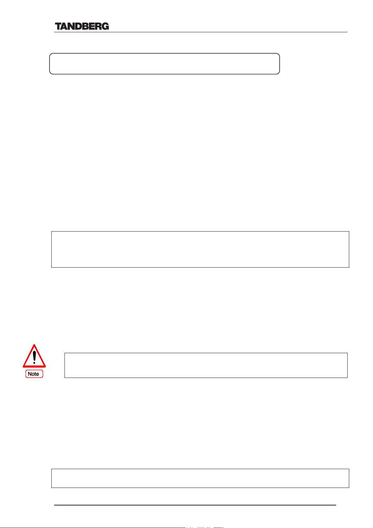
ISDN Aggregation H.221 Frame Structure from 64(56
ISO 13871 BONDING, Mode 1 from 64(56
4.2.1 BONDING
• ISO 13871, BONDING Mode 1 for bit rates from 56 kbps up to 2 Mbps (1 to 30 channels).
• The TANDBERG system can handle relative delay difference between B-channels of up to
0.5 second (i.e. to compensate for different routing of channels).
Example: Channel 1 is delayed 250 ms, channel 2 is delayed 500 ms and channel 3 is
delayed 330 ms. The relative delay difference is then (max. – min.), thus in this case it would
be
500 ms – 250 ms = 250 ms (0.250 sec).
If delay difference is more than 0.5 seconds in the call, the TANDBERG system will display
‘Corrupted data received’ and try to resynchronize the call.
Note: Delay difference will vary depending on the different service providers involved in the
call.
The following are the standard bandwidths on H.320:
30ch – 24 – 23 – 18 – 12 – 8 – 6 – 5 – 4 – 3 – 2 – 1
*
) kbps to 128 kbps
*
) kbps to 2 Mbps
4.2.2 H.221
• For bit rates from 56 kbps up to 128 kbps (1 or 2 channels).
• The maximum relative delay difference between the 2 B-channels is 0.6 second.
• The system will only select H.221 if the far end does not support BONDING or when two
ISDN numbers are dialled.
Only 1 x 64 kbps H.221 support when External Network is used.
4.2.3 Encoding delay
H.320: The latency in a point-to-point call using TANDBERG systems on H.320 (ISDN) varies
between 160-250ms depending on the network performance.
H.323: The latency in a point-to-point call using TANDBERG systems on H.323 (IP) varies
between 120-160ms. (An additional 100ms have to be added for playout buffering).
NOTE, the total delay of a call will be as follows:
Encoding delay + Max. network delay + Decoding delay
D12008 Rev. 11 30
Page 31
Technical Description of TANDBERG 8000 with software version E3/B8
Network delay (and Delay difference) will vary depending on the different service providers
involved in the call.
Decoding delay is typically 1/3 of the encoding delay.
4.3 Data Interface/Application Programmable Interface (API)
Data Standards T.120 Data Communication Protocol
Data TANDBERG Dynamic Data Channel (DDC)
Modem Standard modem commands
Auto/VISCA For control of camera connected to data port 2
Data Interfaces 2 x Data ports, RS-232 (9-pin D-sub), Up to 38400 Baud for Data & Control
The dataports on TANDBERG 8000 are implemented as Digital Circuit Terminating Equipment
(DCE).
The pin-outs for both data ports are the same except pin no. 4, see note below. The connectors
used are female 9-pin D-subs.
• The TANDBERG main camera is normally connected to Dataport 2
• On Data port 2, pin number 4 provides 12V DC / 1 Amps to the main camera
• The device for activation of the plasma monitor’s Screen Saver and the Intelligent XGA<->S-Video
switching should be connected to Data port 1 (See also Ch. 4.4.5).
Signal Name Direction Pin number
Carrier detect, CD From DCE 1
Receive data, RXD From DCE 2
Transmit data, TXD To DCE 3
Data terminal ready, DTR From DCE 4
Signal ground, GND 5
Data set ready, DSR From DCE 6
Ready to send, RTS To DCE 7
Clear to send, CTS From DCE 8
Ring indicator, RI From DCE 9
D12008 Rev. 11 31
Page 32

Technical Description of TANDBERG 8000 with software version E3/B8
4.3.1 Data Protocols
Please refer to ‘Data port User Guide’ (D11943) for details.
There are several different modes for the data ports as described below.
• Data, Dynamic Data Channel mode (data port 1)22
When communicating between two TANDBERG products, this protocol enables the use
of a multitude of applications such as:
• File transfer
• Diagnostics
• Application sharing
• remote control
The Codec operates as a modem according to Hayes’ commands.
• Control mode (data port 1)21
In this mode, the Codec can be controlled by an external user interface.
• Modem mode (data port 1)21
When in a call - DDC mode is activated.
When not in a call - Control mode activated.
• T.120 mode (data port 1)
The T.120 data protocol enables systems from different manufacturers to do data
conferencing- implemented by TANDBERG in the form of the T.120 data
communication protocol (MLP).
• Enables the provision of data conferencing capabilities within an MCU call23.
• Covers many different aspects of data conferencing such as application sharing and
white boarding.
• Makes use of MLP and hence requires a suitable application matching your data
communications requirements. TANDBERG recommends Microsoft NetMeeting
version 2.0/2.1 or Intel’s IBVC (Intel Proshare) for data conferencing.
• Maximum bandwidth for data in this mode is 32 kbps.
Please, refer to the document ‘Data conferencing & T.120 overview’ (D10632) for
details.
• VISCA (data port 2)
For control of cameras using VISCA control protocol.
• AUTO (data port 2)
The auto setting will automatically set the data port 2 dependent on equipment
connected. The following equipment will be automatically identified:
• TANDBERG W.A.V.E. camera. The command set for this camera will be activated.
• Hayes compatible modem. The command set for Hayes will be activated.
• Other control devices. The data port will be set to Control mode.
22
During the time of use, the RS232 Screen saver connector needs to temporarily be disconnected.
23
Depending on the MCU’s capability to support T.120
D12008 Rev. 11 32
Page 33

Technical Description of TANDBERG 8000 with software version E3/B8
4.3.2 Translation in RS232 cable for TANDBERG 8000 dual monitor
TANDBERG 8000 has an Intelligent VGA <-> S-Video switching device connected to Dataport
1 to utilize the local dual monitor. It will switch to the VGA cable (thus XGA resolution24 on
dual monitor) when PC is selected and S-Video cable (xCIF resolution on dual monitor) when
e.g. Main Camera is selected.
Furthermore, whenever the TANDBERG 8000 system receives a video stream / presentation in
XGA resolution, the presentation will be displayed on the dual monitor. This is applicable to
receiving XGA presentations on either the main or the duo video stream.
The command translations done by the chip in the RS232 connector is shown below.
From codec: *S dualmon open = To monitor 1: IN2
To monitor 2: IN4
back to codec: vgamon second
From codec: *P vidin 5 = To monitor 1: IN2
To monitor 2: IN4
back to codec: vgamon second
From codec: *P duovideo ready = To monitor 1: IN2
To monitor 2: IN2
back to codec: vgamon loop
From codec: *P vidin 1,2,3 or 4 = To monitor 1: IN2
To monitor 2: IN4
back to codec: vgamon loop
Note: The command dualmon open is a common command for all DuoVideo sessions, and thus
not only for PC. This means that duo video with aux, vcr and doc cam will also be shown in
VGA mode.
24
XGA only supported from software E1 onwards
D12008 Rev. 11 33
Page 34
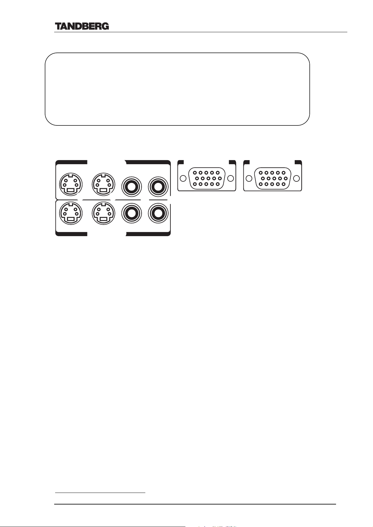
Technical Description of TANDBERG 8000 with software version E3/B8
4.4 Video Interfaces and Special Video Features
Video Inputs 2 x S-video, Mini-DIN Connector (1 S-Video Input is Used by the Main Camera)
2 x Composite, RCA Connector
1 x XGA, 15 pins
Ethernet connector (used by PC Soft Presenter)
Video Outputs 2 x S-Video, Mini-DIN Connector (Single/Dual Monitor)
2 x Composite, RCA connector (Single/Dual Monitor)
1 x XGA
VGA, SVGA and XGA
Video Formats PAL or NTSC
The TANDBERG 8000 Codec has the following video connectors:
Video in PC VGA in
1. Main cam 2. Aux cam
3. Doc cam 4. VCR
25
, 15 pins
23
(Native Resolutions)
VGA out
1. Single 2. Dual 3. Single 4. Dual
Video out
4.4.1 Video Inputs
• Video Input 1-2 support S-Video through Mini-DIN connectors.
• Video Input 3-4 support composite signals through RCA connectors.
• Video Input 2 or 3 may be set as ‘Document camera input’ from the menu settings (Selected
with the remote control button ‘Doc Cam’ and will transmit Digital Clarity by default).
• Levels:
• Composite; 1 Vpp, 75 ohm
• S-Video (Y/C); Y: 1 V
C (PAL): 0.3 V
, 75 ohm
pp
, 75 ohm
pp
C (NTSC): 0.28 Vpp, 75 ohm
4.4.2 XGA Input (‘PC Presenter’)
The TANDBERG 8000 codec has a standard XGA Input. The supplied VGA cable should be
connected to the codec’s XGA Input, thus making it simple to use for ad hoc PC presentations
with no need for additional hardware.
23
The TANDBERG 8000 will transmit the Native Resolutions of XGA
, SVGA or VGA without
scaling. If the far end does not support H.263+ custom formats, the system has the ability to
scale the XGA input to CIF and 4xCIF.
25
XGA only supported on software E1
D12008 Rev. 11 34
Page 35
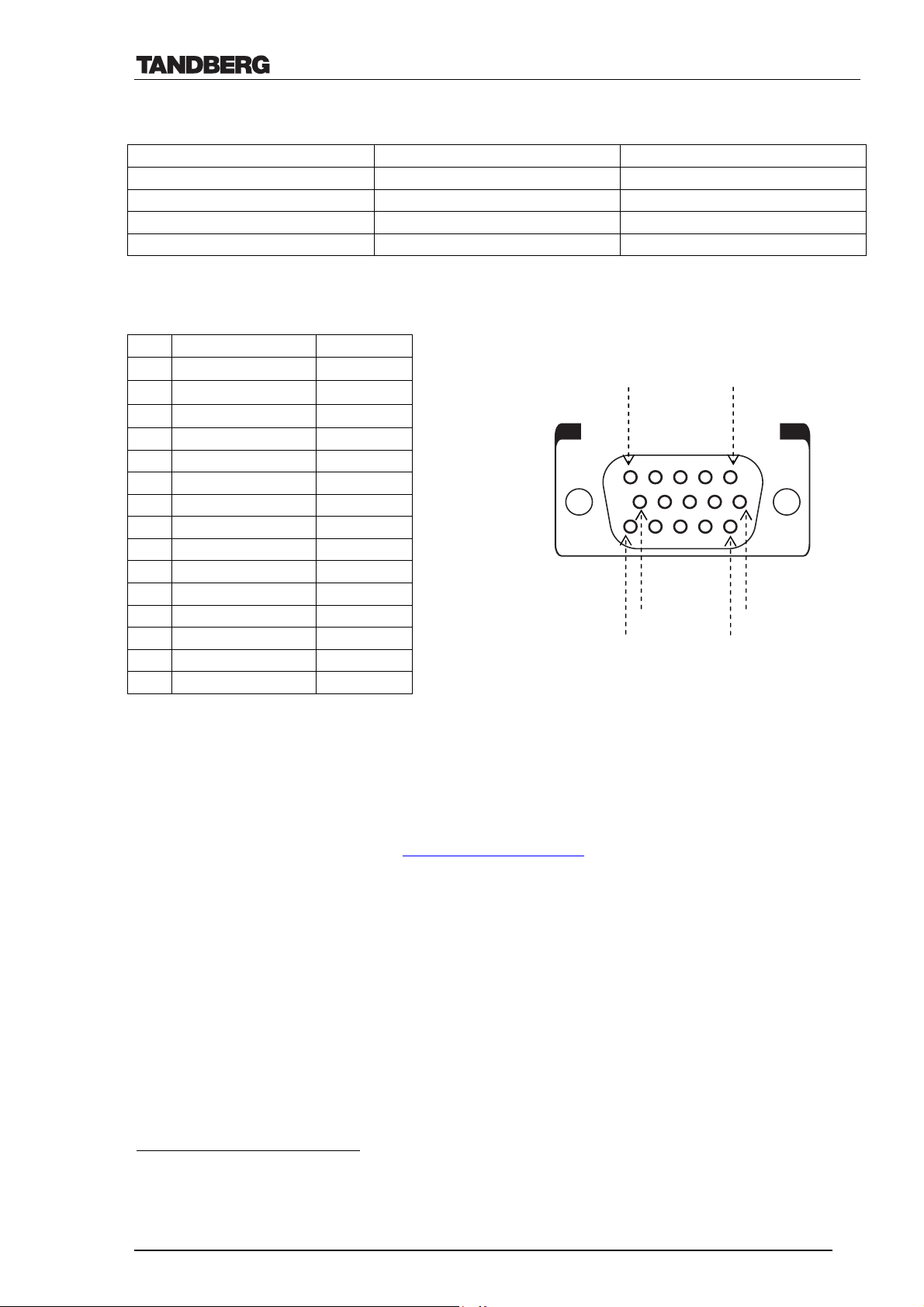
Technical Description of TANDBERG 8000 with software version E3/B8
The following VGA, SVGA and XGA inputs are supported26:
VGA SVGA XGA
640X480_60Hz 800X600_56Hz 1024X768_60Hz
640X480_72Hz 800X600_60Hz 1024X768_70Hz
640X480_75Hz 800X600_72Hz 1024X768_75Hz
640X480_85Hz 800X600_75Hz
800X600_85Hz
4.4.2.1 VGA, SVGA and XGA Pin layout
Pin Function Volt/Ohm
1 Red signal
2 Green signal
3 Blue signal
0.7v/75Ω
0.7v/75Ω
0.7v/75Ω
5
1
4 Ground
5 Ground
6 Red ground
7 Green ground
8 Blue ground
9 No connection
10 Ground
11 No connection
12 No connection
13 Horizontal sync* TTL
15
10
6
11
14 Vertical sync* TTL
15 No connection
(*) The system supports the synchronisation method RGBHV on both VGA input and output.
4.4.3 PC Soft Presenter
The system has implemented a feature that allows PC images to be shown to the codec. A
software from ‘Virtual Network Computing’ (VNC) needs to be installed on the PC to make use
of this feature (free download from http://www.realvnc.com).
When correctly set up27, the PC image will be used as video input by the system whenever the
PC button is pressed on the remote control28.
Note: The VNC Server’s Display Number and Password need to be set on the codec29.
Please, see the User Manual for guidelines of setting up the PC Soft Presenter.
Note: PC Soft Presenter supports the same resolutions as the PC presenter (XGA input). In
addition, the VNC server will scale any SXGA input down to XGA.
26
Implemented according to VESA standards (VGA=Video Graphics Array, SVGA=Super VGA, XGA= eXtended VGA).
Note: If image from PC in use is not displayed correctly, changing the PC’s resolution to XGA -> VGA may help.
27
If problems getting VNC to work, one may have to update the driver(s) for the PC graphical card and/or the PC network card
28
The VNC program must be installed as a Server on the PC in use (the codec being the client) and supports Windows, Unix and Macintosh.
29
Password is encrypted
D12008 Rev. 11 35
Page 36
Technical Description of TANDBERG 8000 with software version E3/B8
4.4.4 Video Outputs
Video Output 1 and 3 provides main video (incoming/Self view [and PIP], Still Image and
menu). Video Output 2 and 4 provides Self-view and Still Image Graphics (Dual monitor).
• Video Output 1-2 supporting S-Video through Mini-DIN connectors.
• Video Output 3-4 supporting Composite signals through RCA connectors
• Levels:
• Composite; 1 Vpp, 75 ohm load
• S-Video (Y/C); Y: 1 Vpp, 75 ohm load
C (PAL): 0.3 Vpp, 75 ohm load
C (NTSC): 0.28 Vpp, 75 ohm load
4.4.5 XGA Output30
TANDBERG 8000 is provided with an XGA output port that scales the images- when requiredto fit XGA monitors.
The XGA output may be set as either a single or a dual monitor. It may also be set to Loopback,
in which case video from the XGA input is shown on the XGA output.
The following VGA, SVGA and XGA outputs are supported and may be received as Native
Resolutions from a remote system:
VGA SVGA XGA28
640X480_60Hz 800X600_60Hz 1024X768_60Hz
Note: By pressing the following buttons on the remote control it is possible to toggle between
the settings VGA out loop and VGA out main:
Snapshot – Far End – Snapshot – 1
• TANDBERG 8000 has an Intelligent VGA <-> S-Video switching device connected to
Dataport 1 to utilize the local dual monitor. It will switch the to VGA cable (thus SVGA
resolution on dual monitor) when PC is selected and S-Video cable (xCIF resolution on
dual monitor) when e.g. Main Camera is selected (ref. ch. 4.3.2).
Furthermore, whenever the TANDBERG 8000 system receives a video stream /
presentation in XGA resolution, the switching device will switch to VGA output. The
presentation will then be displayed on the dual monitor. This is applicable to receiving
XGA resolution on the main or the duo video stream.
30
XGA only supported from software E1 onwards
D12008 Rev. 11 36
Page 37

Technical Description of TANDBERG 8000 with software version E3/B8
4.4.6 Optimized Video Compression
The ITU standard H.263 provides:
• Optimized compression and decompression of video at lower bandwidths.
• A sharper picture than provided by H.261.
• Improved contrast and enhanced clarity of the finer details within an image.
• Improved motion handling that removes the characteristic blocking that tends to occur during
normal H.261 movement.
• Near broadcast quality motion handling (iCIF/iSIF) is achieved with the implementation of
certain H.263 annexes, commonly referred to as H.263+ (annex N) and H.263++ (annex W).
• 4xCIF/4xSIF live video
The ITU standard H.264 provides considerably better video quality at lower bandwidths. It has
been developed with strong TANDBERG participation in joint workgroups of ITU-T and ISO.
H.264 is based on the ISO standard MPEG-4.
The TANDBERG 8000 system supports H.264 video compression in both CIF and SIF
resolutions31. An encoding and decoding rate of a high-quality 30fps is achieved. H.264 may be
used on the TANDBERG 8000 system for bandwidths of up to 768 kbps.
Under the preconditions named above and depending on the far end’s H.264 support, the
TANDBERG system will select H.264 as video compression standard if H.264 has been
activated in the menu.
In case H.264 is unavailable at the far end or if the above preconditions are not fulfilled, the
TANDBERG system will preferably select H.263.
The TANDBERG system will select H.261 only in case the far end system supports no better
video compression algorithm.
4.4.7 Intelligent Video Management (IVM)
It is possible to configure the picture sent from the system depending upon specific requirements
and applications adding an additional level of flexibility and adaptability:
Generally, the IVM will always try to transmit the format closest to the video input format.
Motion: When there is a need for higher frame rates, typically when a large number of
participants are present or when there is a lot of motion in the picture.
At low bit rate:
• CIF will be used from a PAL video input
• SIF from NTSC
• VGA/SVGA/XGA from PC, Digital Clarity
At high bit rate:
• iCIF will be used from a PAL video input, Natural Video
• iSIF from NTSC, Natural Video
• VGA/SVGA/XGA from PC, Digital Clarity
31
H.264 only supported from software E2 onwards
D12008 Rev. 11 37
Page 38

Technical Description of TANDBERG 8000 with software version E3/B8
Sharpness: Improved quality of detailed images and graphics, lower frame rate, ideal for
enhancing quality at lower bandwidths.
• 4xCIF will be used from a PAL video input, Digital Clarity
• 4xSIF from NTSC, Digital Clarity
• VGA/SVGA/XGA from PC, Digital Clarity
Auto: Selected when there is a need for both motion handling and high quality of images and
graphics. The system will automatically adjust frame rate and sharpness dependent on
movement.
At low bit rate:
• CIF will be used from a PAL video input
• SIF from NTSC
• VGA/SVGA/XGA from PC, Digital Clarity
At high bit rate:
• iCIF will be used from a PAL video input, Natural Video
• iSIF from NTSC, Natural Video
• VGA/SVGA/XGA from PC, Digital Clarity
When Document Camera is selected:
• 4xCIF will be used from a PAL video input, Digital Clarity
• 4xSIF from NTSC, Digital Clarity
4.4.7.1 IVM Resolution
The following table shows relationship between Transmission modes selected by the system
when Motion or Sharpness is set in the Call Quality menu. IVM will use this table to optimize
the Video quality, according to the capabilities of the remote system(s):
Basic Video
Quality
MOTION PAL iCIF@50 -> CIF -> QCIF
MOTION NTSC iSIF@60 -> iCIF@60 -> SIF@60 -> CIF -> QCIF
MOTION VGA CIF -> QCIF
MOTION SVGA CIF -> QCIF
MOTION XGA CIF -> QCIF
SHARPNESS PAL 4xCIF -> VGA -> CIF -> QCIF
SHARPNESS NTSC 4xSIF -> 4xCIF -> VGA -> SIF -> CIF -> QCIF
SHARPNESS VGA VGA -> 4xCIF -> CIF -> QCIF
SHARPNESS SVGA SVGA -> 4xCIF -> VGA -> CIF -> QCIF
SHARPNESS XGA XGA -> SVGA -> 4xCIF -> VGA -> CIF -> QCIF
Video
Input
Transmission mode selection rules
32
4.4.8 Duo Video
The TANDBERG 8000 is capable of receiving and transmitting two simultaneous H.320 (ISDN
or NET interfaces), H.323 or Leased Line E1/T1 video signals33.
32
System will always try the first transmission mode, and then try the one to the right and so on (as indicated by the arrows) until the proper
transmission mode is found.
33
Only possible if the far site can receive Duo Video and both sites have two monitors connected. Natural Video is not supported in Duo Video
mode.
D12008 Rev. 11 38
Page 39

Technical Description of TANDBERG 8000 with software version E3/B8
Automatic Duo Video set up
When DuoVideo mode is set to Auto and the remote control buttons; DocCam, Aux, VCR or PC
are selected, the system will use this video input as its Duo Video source. The call bandwidth
will be split between the main video (including audio etc.) and the Duo Video. Once the Main
camera is selected, the system will use all its bandwidth for this video source.
When network is H.323:
The system will use approximately 1/2 of its original bandwidth for Duo Video (i.e. the system
decides the DuoVideo rate according to the available HSD34 data rates- the DuoVideo rate will
be less than the main video rate for higher call rates).
When network is ISDN:
The following table applies for Duo Video Bandwidths*:
Call rate (kbps) Duo Video rate (kbps)
128 64
192 64
256 64
320 128
384 128
512 128
768 256
1152 384
1472 384
1536 384
1920 384
1719 * For restrict use 56k multiples: E.g. 112 -> 56, 168 -> 56 etc
When using the Duo Video feature the main video bandwidth can be calculated by using the
formula below:
Main video rate = Call rate – DuoVideo – Audio – Framing (1.6 kbps) – Encryption control
(0.8 kbps)
E.g. A 320kbps call using G.722 (56kbps) audio will use:
320kbps – 128 – 56 – 1.6 – 0.8 = 133.6 kbps for main video
When network is Leased Line E1/T1: the maximum Duo Video bandwidth is 768 kbps.
It is possible to change the picture quality (e.g. Digital Clarity) even after a Duo Video signal is
set up (Presentations Menu – Duo Video Quality).
Note: In a MultiSite call, the MultiSite ‘host’ can transmit Duo Video to the other sites if these
sites have Duo Video support. If some of the connected sites are single monitor systems and
have software B5 or later the single monitor systems will see the Duo Video picture (e.g.
presentation) and the Duo Video sites will see both presenter and the presentation.
34
Only possible when both systems have software B3 or later. Description of HSD is found in ITU recommendations: H.221, H.242 and H.243
D12008 Rev. 11 39
Page 40

Technical Description of TANDBERG 8000 with software version E3/B8
The Duo Video functionality supports all H.320 standards, thus it is possible to call two ordinary
systems, but there is no audio transmitted in the second duplex H.320 signal.
Duo Video is supported using the H.263 and H.261 video compression standards.
4.4.9 Digital Clarity35
TANDBERG 8000 has the ability to transmit and receive live images using the Native
Resolutions VGA, SVGA, XGA or 4xCIF/4xSIF. This feature is called Digital Clarity.
When the document camera or the PC is selected, Digital Clarity is automatically selected by the
system- the live picture quality will then be crystal clear and the frame rate lower compared to
using CIF/SIF36. (See also ch.4.4.7 ‘ Intelligent Video Management’)
The Selfview picture will always be shown in PAL/NTSC video quality.
Whenever the TANDBERG 8000 system receives a video stream / presentation in XGA
resolution, the presentation will be displayed on the high-resolution dual monitor. This is
applicable to receiving XGA resolution on the main or the duo video stream.
4.4.10 Natural Video (iCIF/iSIF)37
The TANDBERG 8000 is capable of handling interlaced CIF/SIF live video quality.
Using the ITU standards’ H.263+ and H.263++ capabilities, iCIF/iSIF enables TANDBERG
8000 to transmit and receive a true interlaced video image near TV quality (i.e. 60 fields per
second).
Note: Natural Video may only be used on bandwidths of 384 kbps and above and will
automatically be selected at bandwidths of 768 kbps and above if supported by the other system.
Natural Video is disabled in H.323 Multi Site calls, H.320 Contionous Presence Multi Site calls,
Duo Video calls and if VGA output is used as Main or Dual Monitor.
4.4.11 Native Resolutions
The following live video resolutions are supported on the system:
Native NTSC38:
4xSIF (704 x 480 pixels), Digital Clarity
Interlaced SIF (352 x 480 pixels), Natural Video
SIF (352 x 240 pixels)
Native PAL:
4xCIF (704 x 576 pixels), Digital Clarity
Interlaced CIF (352 x 576 pixels), Natural Video
CIF (352 x 288 pixels)
QCIF (176 x 144 pixels)
SQCIF (128 x 96 pixels)
Native PC Resolutions:
XGA39 (1024 x 768 pixels), Digital Clarity
35
Receive Digital Clarity is implemented on all TANDBERG systems (Transmit Digital Clarity is part of the NPP software packet)
36
Only possible if the remote site can transmit/receive video in 4xCIF/4xSIF, VGA, SVGA, XGA.
37
To exclude the sending of iCIF/iSIF formats and prevent Interlaced bearer capabilities to be set on system, turn Natural Video off .
38
Source Input Format SIF (4xSIF, iSIF) is an NTSC based video format (Defined in MPEG-1 standard).
39
XGA only supported from software E1 onwards
D12008 Rev. 11 40
Page 41

Technical Description of TANDBERG 8000 with software version E3/B8
SVGA (800 x 600 pixels), Digital Clarity
VGA (640 x 480 pixels), Digital Clarity
4.4.12 One-touch Snapshot
The TANDBERG 8000's intelligent One-touch Snapshot button makes it easy to send and
receive an image of the highest possible resolution.
• If calling to a dual monitor system the still image will appear on the dual monitor.
• A preview of the still image is possible (set-up in the presentation setting).
• To send a snapshot inside a MultiSite call a snapshot can be sent to all other participants from
the site that holds the floor.
• If the far end supports H.263+ custom formats, snapshot can be sent in VGA, SVGA or
4xSIF.
• If the far end does not support H.263+ custom formats, snapshot will be sent in 4xCIF.
• It is possible to configure the system to always send snapshots from a particular video input,
but requesting a snapshot from another system will always display the current image (i.e. the
far end image seen on screen).
Snapshot is implemented according to the ITU standard H.261 Annex D.
By using the Selfview button one may toggle between the last sent/received snapshot and the
self-view picture (shown on the dual monitor). It is also possible to view a still image on singlemonitor systems.
4.4.13 Screen Saver
If the system is not in a call, a text string will be shown on the monitor screen after 9 minutes.
The user is prompted to select screen saver delay of 30 minutes, 60 minutes or 3 hours. If the
user does not respond within 1 minute, the screen saver is activated and both monitors will go
black (i.e. the codec sends out a black image).
Once the remote control is touched (or any other activation of the system; such as an incoming
call), the screen saver will be switched off.
If the system is used for local presentation (i.e. not in a call), it is possible to delay the
screensaver prompt via the Quick Keys on the remote control (for 1 or 3 hours).
D12008 Rev. 11 41
Page 42
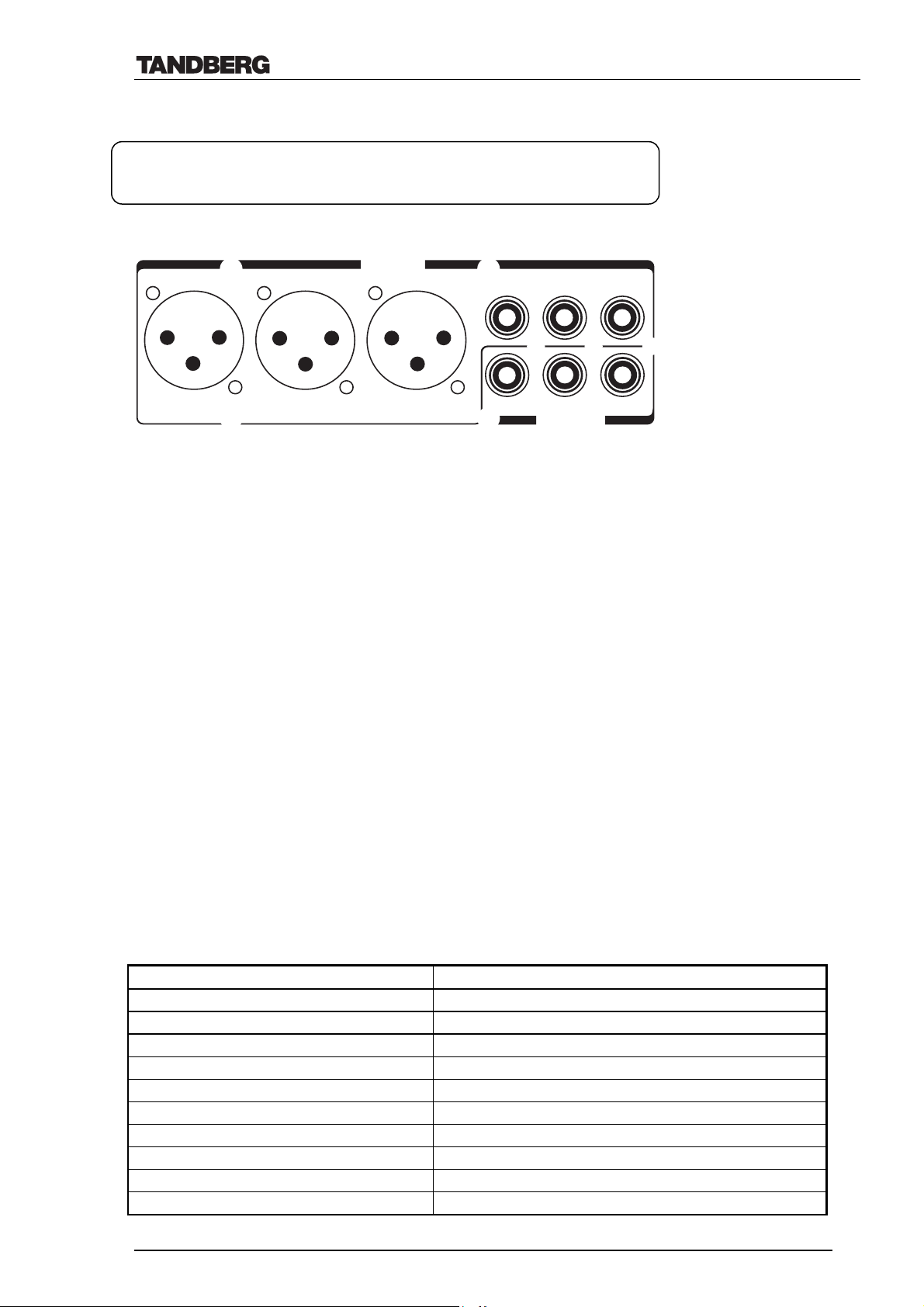
Technical Description of TANDBERG 8000 with software version E3/B8
4.5 Audio Interfaces and Special Audio Features
Audio Inputs 3 x Microphone, 24V Phantom Powered, XLR Connector
3 x Audio, RCA Connector (Line Level)
Audio Outputs 3 x Audio, RCA Connector (Line Level)
The TANDBERG 8000 Codec has the following audio connectors:
Audio in
45 -
1
Mic.
123
1
Mic.
2
Mic.
3
4.5.1 Audio Inputs
The TANDBERG 8000 Codec has a total of six audio inputs, three microphone audio inputs and
three line level inputs.
General:
• The input gains on all six inputs are independently adjustable.
• All six inputs can be independently enabled or disabled.
• By default, all inputs are enabled, ready to be connected with an audio source.
• All audio input signals are mixed together if enabled.
• Inputs that are disabled will be muted automatically.
• When selecting ‘Restore Defaults’, all audio settings will be set to factory-programmed values.
• The default settings are correct for Audio Technica AT841-R microphone (Mic in 1-3) and
for most consumer electronics (CD-players, cassette recorders, VCRs, etc., Audio in 4-6).
• After installation, audio input level settings should remain unchanged.
• When storing presets, the selected audio settings are stored together with the video
inputs/camera positions.
AUX
AUX
2 -
Audio out
6 -
3 -
VCR
VCR
4.5.1.1 Specification microphone Inputs
Mic in 1-3:
These inputs are intended for electret type microphones. The inputs are balanced. By using the
audio input level menu, the gain can be adjusted correctly for a wide range of microphones.
Connector label MIC 1, 2 and 3
Signal type Balanced
Connector (Codec) XLR-F, pin 1-gnd, pin 2-hot, pin 3-cold/neutral
Phantom power voltage 24 V +/- 5%
Phantom power resistor, pin 2 1200 ohms
Phantom power resistor, pin 3 1200 ohms
Max. Ph. Power current (per Mic) 12 mA
Input impedance between pin 2 and 3 2400 ohms
Max. Input level (max. input gain) 6.2 mVpp
Max. Input level (min. input gain) 83 mVpp
Range - menu adjustable input gain 22.5 dB (16 steps of 1.5 dB)
D12008 Rev. 11 42
Page 43
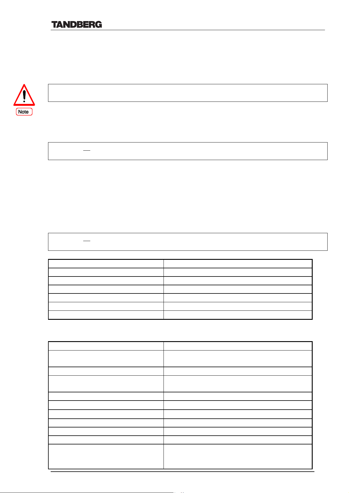
Technical Description of TANDBERG 8000 with software version E3/B8
4.5.1.2 Specification audio line Inputs
Audio in 4:
Input 4 enables connection of a microphone amplifier or a microphone mixer if more than 3
microphones are required.
When using an external mixer, it is very important that this is a fixed mixer. Automatic, smart
and other types of adaptive mixer will cause the echo canceller to malfunction.
Audio in 5:
This input is labelled AUX and is intended for connection to external playback devices or to
telephone add-on hybrids.
As there is no acoustic echo canceller on this input, microphone mixers should not be
connected.
Audio in 6:
This input is specially designed for connection to a VCR but may also be connected to other
playback devices. This input will automatically be reduced if a microphone is activated (VCR
ducking).
Note: When mode is set to Auto for this input, it will not be enabled unless Video input 4
(i.e.VCR) is selected.
As there is no
acoustic echo canceller on this input, microphones mixers should not be
connected.
Connector label AUDIO IN 4, 5 and 6
Signal type Unbalanced
Connector (Codec) Female RCA/Phono, sleeve-ground, centre-signal
Input impedance 10K ohms
Max. Input level (max. input gain) 1.17 Vpp
Max. Input level (min. input gain) 15.5 Vpp
Range - menu adjustable Input gain 22.5 dB (16 steps of 1.5 dB)
4.5.1.3 Specification standard microphone (AT841R)
Mic. Audio-technica AT841R Specification
Type Fixed-charge back plate permanently polarized
condenser
Connector (Codec) XLR, pin 1-gnd, pin 2-hot, pin 3-cold/neutral
Polar pattern Omnidirectional in hemisphere above mounting
surface
Phantom power 9 - 52 V DC, 2 mA typical
Sensitivity
Impedance
-35 ± 3 dBm (0dB=1 V/1Pa)
200 ohm (±30% at 1kHz)
Maximum Input sound level 131 dB, 1 kHz at 1% T.H.D.
Signal to Noise ratio Greater than 69 dB at 1 kHz/1 Pa
Weight 81 gram
Dimensions, microphone Width 65 mm/2,56”
Length 65 mm/2,56”
Height 15 mm/0.59”
D12008 Rev. 11 43
Page 44
Technical Description of TANDBERG 8000 with software version E3/B8
4.5.1.4 Specification Audio Science microphone (Optional Equipment)
The microphone used in the Audio Science is a Crown PZM-30D. The basic specifications for
this microphone are listed below:
Crown PZM-30D microphone Specification
Type Pressure Zone Microphone, Electret condenser
Connector (Codec) XLR, pin 1-gnd, pin 2-hot, pin 3-cold/neutral
Polar pattern Hemispherical
Phantom power 12 - 48 V DC, 1.1 mA typical
Sensitivity -43 dBm (0dB=1 mW/1Pa)
Impedance 240 ohm
Maximum Input sound level 150 dB, 1 kHz at 1% T.H.D.
Signal to Noise ratio Greater than 74 dB at 94 dB SPL
Weight 184 gram, microphone only
Dimensions, Audio Science Width 121 cm / 47.6”
Length 61 cm / 24”
Height 33 cm / 13”
Cable 14 m / 47 feet
When connecting the Audio Science microphone the audio input level should be adjusted to
approx. 19.5 dB (in the level settings menu) to obtain optimum performance.
4.5.2 Audio Outputs
In addition to the Codec internal alerting speaker, the TANDBERG 8000 Codec has three audio
outputs. The output levels on all three outputs are independently adjustable.
General:
• Using the ‘Audio Output’ menu, the outputs can be independently enabled or disabled.
• Disabled outputs will be muted.
• The audio output levels specify the maximum level of the output.
• When selecting ‘Restore Defaults’, all audio settings will be set to factory-programmed
values.
• The default settings are correct for the TANDBERG Natural Audio modules and for most
consumer electronics (televisions, cassette recorders, VCRs, etc.).
• After installation, audio output level settings should remain unchanged.
Tip to integrators:
The videoconferencing dial tone of the system has a fixed frequency of approximate 420 Hz
and a constant level of 24 dB below full scale. The dial tone may therefore be used for
calibrating external audio equipment, in order to obtain a proper gain structure. The dial tone
is present on the codec’s audio output 1 only, but as the full-scale output levels of all outputs
are the same, any setting found on audio output 1 can be directly used on the other outputs.
To calibrate to proper level use the audio output level settings in the codec’s menu or adjust
the input gain of the external audio device. To ensure correct calibration, it is important that
the codec’s volume setting is set to maximum and that all echo cancellers are disabled. Do
not calibrate on dial tones in audio calls, as these are not guaranteed to have the same fixed
frequency and level.
D12008 Rev. 11 44
Page 45

Technical Description of TANDBERG 8000 with software version E3/B8
4.5.2.1 Specification Audio line Outputs
• Audio out 1: Intended for connection to TANDBERG Natural Audio Module, televisions or
audio amplifiers with loudspeakers. The signal on this output is a mix of audio from the
remote side, audio from Audio in 5 and audio from Audio in 6. Alert tones and DTMF tones
will also be present on this output.
The remote volume control will control the level of the speaker output (Audio out 1).
• Audio out 2: Intended for connection to audio recording equipment or to telephone add-on
hybrid or to an adjacent room. The signal on this output is a mix of audio from the remote
side, audio from Mic in 1-3, audio from Audio in 4 and audio from Audio in 6. Local DTMF
tones will be present, but alert tones will not be present.
• Audio out 3: Intended for connection to a VCR or other recording equipment. The signal on
this output is a mix of audio from remote side, audio from Mic in 1-3, audio from Audio in 4
and audio from Audio in 5. Neither local DTMF nor alert tones will be present.
The remote volume control has no effect on Audio Output 2 and 3.
Connector label Audio Out 1, 2 and 3
Signal type Unbalanced
Connector (Codec) Female RCA/Phono, sleeve-ground, centre-signal
Output impedance 680 ohms
Max. Output level (max. level setting,
15.3 Vpp
volume control set to max.)
Max. Output level (min. level setting,
1.15 Vpp
volume control set to max.)
Range - menu output level control 22.5 dB (16 steps of 1.5 dB)40
Volume control attenuation (only line
0 to 21 dB + mute (steps of 1.5 dB)
output 1)
4.5.3 Flexible Audio Features
• The TANDBERG 8000 has a flexible integrated audio system, which consists of 6 audio
inputs where any number of audio inputs can be active at the same time.
• When storing presets, all audio settings will be stored together with the selected video
source/camera position.
• The TANDBERG 8000 has lip synchronization for audio.
• Intelligent Audio Mixing: Through adaptive weighting, the system establishes one
microphone as active, automatically determined by the user who is speaking. This feature
prevents sounds from inactive microphones or other audio sources from being picked up and
eliminates distracting background noise. Intelligent Audio Mixing leverages the capabilities
of the four separate acoustic echo cancellers.
• Audio Level Meters. Measures and displays the audio input level for each audio source
independently, providing an on-screen visual aid to ensure optimum audio performance and
simplifying installation. ‘Centre point mark’- or slightly below- is the preferred value for best
performance.
40
Additional attenuation is possible on Audio Output 1 by using the remote volume control setting.
D12008 Rev. 11 45
Page 46

Technical Description of TANDBERG 8000 with software version E3/B8
4.5.4 Acoustic Echo Cancellers
Acoustic echo cancelling is provided on Mic in 1-3 and Audio in 4. Each of these inputs has a
dedicated acoustic echo canceller. With a separate echo canceller per microphone, the echo
cancelling is vastly improved compared to using one common canceller for all microphones.
• Echo cancelling tail length lowest frequency sub band 340 ms.
• Echo cancelling tail length highest frequency sub band 250 ms.
• Max acoustic echo cancellation 70 dB.
If an external echo canceller is used, the internal echo cancelling function should be switched
off for the respective audio input.
4.5.4.1 Adjusting the Acoustic Echo Cancellers
The TANDBERG 8000 has the ability to manually adjust the echo cancellers in two ways to
obtain the best performance for rooms with special acoustic environments; room size and
motion, each controlled by a 0-15 slidebar placed under the echo control menu. Each slidebar
defines one common setting for all the acoustic echo cancellers in a system.
When adjusting these settings, please remember that in a video conference between system A
and system B, any echo problem on system A will be experienced by the users of system B and
vice versa.
Room size:
For optimum performance, this setting should be adjusted when the system is installed in a new
room.
This setting allows optimization of the echo canceller to the acoustic size of the room where the
system is placed. The setting should reflect the acoustic size of the room; two physically equal
sized rooms may require different settings, depending on the materials in walls, floor etc. If the
materials are hard (windows/metal etc.), the appropriate setting is higher; if the materials are
soft (carpets/curtains etc.), the appropriate setting is lower.
Correct setting of the room size parameter will lead to significantly increased echo canceller
performance. Adjust the setting if one of two symptoms occurs:
1) There is still some residual echo after a long period of training (audio from the
loudspeaker, but no talking in the room where the system reside); Increase the room size
setting.
2) The system adapts slowly to acoustic changes in the room (door opens, persons
moving etc.); Decrease the room size setting.
Please note that the system will have to readapt each time the room size setting is changed.
Motion:
If the system suffers from echo caused by heavy movements in the room, for example people
moving close to the loudspeaker and/or microphone; increasing this setting (i.e. number next to
slidebar) may reduce the problem.
By increasing this setting, limited voice switching is introduced in addition to the echo
cancellation; the higher the setting, the more voice switching is introduced. Therefore, a too high
setting may result in clipped words etc. during double talk situations.
D12008 Rev. 11 46
Page 47

Technical Description of TANDBERG 8000 with software version E3/B8
This setting is without memory (i.e. the system does not have to readapt when the movement
setting is changed).
4.5.5 Noise Reduction (NR)
Two sorts of noise can be removed when using the TANDBERG 8000, namely low frequency
noise and constant noise. The noise reduction algorithms are either both enabled or both
disabled.
The constant noise reduction algorithm available on the TANDBERG 8000 is able to reduce
noise with a slowly varying level and frequency response, i.e. the reduction is based on an
assumption that the noise is constant over time. Therefore, it will reduce noise from fans, airconditioning and PCs, but it will not remove conversation and noise caused by slamming doors,
coughing etc.
In case of very high noise levels, the constant noise reduction algorithm may introduce some
audio distortion. If distortion is a problem, verify that the microphone input gain is set properly.
Too low gain may cause distortion. If gain is set incorrectly, move the microphones closer to the
person speaking and adjust the input gain properly.
4.5.6 Audio levelling/ Automatic Gain Control (AGC)
The TANDBERG 8000’s Automatic audio levelling feature will ensure that the transmitted
audio will always be at the same level.
• There are four independently selectable audio leveller/AGCs in the system; one common for
Mic 1, 2 and 3 and Audio in 4, one for Audio in 5, one for Audio in 6 and one for audio from
the remote side.
• When enabled, the audio levellers try to keep the signal from the corresponding input at a
constant, fixed level, by attenuating very strong signals and amplifying weak to medium
signals. Very weak signals, i.e. normal background noise alone, will not be amplified. In very
noisy environments, the audio levelling should be turned off for best performance.
• The main purpose of the leveller is to automatically adjust the signals to ensure that each sub
signal in a mix of different sub signals has comparable levels.
• The leveller will also compensate for different speaker levels and different distances from the
person speaking to the microphone.
• To ensure correct behavior of the leveller it is crucial that the input gain settings are adjusted
correctly using the ‘Audio Input level setting’ menu. The leveller will not compensate for
severe maladjustments of the input gain settings.
• If using the Audio Bridging feature and calls to mobile phones or analogue phone systems
result in low audio, try setting the ‘Received Audio’ AGC to ON.
D12008 Rev. 11 47
Page 48

Technical Description of TANDBERG 8000 with software version E3/B8
4.5.7 VCR Audio Features
• When a VCR is connected to Audio In 6- and VCR is selected on the remote control- the
audio from the VCR is transmitted to the other side. The audio will also be heard in the local
loudspeaker.
• When recording, both local and far end audio will be recorded when VCR is connected to
Audio Out 3.
• Some VCRs (and some other recording equipment) connect the signal on their input directly
to the output when in idle or record mode. This feedback loop will cause echo, both locally
and on the remote side. The Codec has a facility that automatically detects and removes this
feedback loop. This feature is provided on the Audio in 6 / Audio out 3 pair of connectors
only.
• VCR Ducking automatically reduces the audio level during a VCR transmission when one or
several persons speak (from either site). ). I.e. when audio is detected by either Microphone
1-3, Audio Input 4-5 or the incoming audio, VCR Ducking will decrease the audio from
Audio Input 6 (VCR). VCR Ducking will automatically adjust the level of the VCR input
back to normal if no other audio (than that of the VCR) is detected. This allows for easy
voice-over commentary during a VCR broadcast.
4.5.8 Telephony
The system supports point-to-point voice only calls both on the ISDN and IP interfaces, by
using the audio compression algorithms described in ch. 4.5.11. See also ch. 4.7 ‘TANDBERG
MultiSite’ for adding telephony into a MultiSite call.
4.5.9 Analogue Telephone add-on (US option only)
It is possible to bring in a telephone participant in the videoconference. This is called telephone
add-on and is similar to the VCR mode in audio functionality. This feature requires extra
analogue telephone add-on equipment.
Please, note the TANDBERG 8000 has the ability to include ISDN telephone calls to mobile
phones or analogue phones in a video meeting without any external equipment (ref. Ch. 4.7).
4.5.10 Microphone Off
Pressing the Mic off key on the remote control will mute audio from Mic1, Mic2, Mic3, and
Audio in 4. It will not mute audio from Audio in 5 and Audio in 6. When the microphone is
turned off any and any of the microphones detects audio, the mic off symbol will flash to warn
the user.
D12008 Rev. 11 48
Page 49

Technical Description of TANDBERG 8000 with software version E3/B8
4.5.11 Audio Compression Algorithms
The following audio algorithms are supported on the TANDBERG 8000:
• G.711 48/56/64 kbps, 3.1 kHz bandwidth.
• G.728 16 kbps, 3.1 kHz bandwidth.
• G.722 48/56/64 kbps, 7 kHz bandwidth.
• G.722.1 24 kbps or 32 kbps, 7 kHz bandwidth41.
When system set to Auto, the following are the preferred audio quality priorities on call rates
above 192 kbps:
1. G.722 (64 H.323)
2. G.722 (56 H.320)
3. G.722 (48 H.320)
4. G.722.1 (32 H.320, H.323)
5. G.722.1 (24 H.320, H.323)
6. G.728
7. G.711 (64,56,48)*
When system set to Auto, the following are the preferred audio quality priorities on call rates
below or equal to 192 kbps:
1. G.722.1 (24 H.320, H.323)
2. G.722.1 (32 H.320, H.323)
3. G.728
4. G.722 (56 H.320)
5. G.722 (64 H.323)
6. G.722 (48 H.320)
7. G.711 (64,56,48)*
(*) H.323 and H.320 will always choose µ-Law before a-Law (for G.711). Telephony will
choose algorithm according to the network used.
When using MultiSite and all sites are talking at the same time, the audio from all sites will be
processed together. This means all the site’s audio will be heard locally.
41
24 kbps is used on call rates ≤192 kpbs, 32 kbps >192 kbps.
D12008 Rev. 11 49
Page 50

Technical Description of TANDBERG 8000 with software version E3/B8
4.6 System Management
TANDBERG provides a comprehensive set of management tools, and is committed to the use of
standards-based tools.
The TANDBERG 8000 can be managed in many ways:
Locally by remote control
Locally by a computer connected directly to the videoconferencing system (e.g. via
RS232, a standard asynchronous serial port or via the codec’s Ethernet port using a
crossover cable)
Remotely, by a computer connected to the videoconferencing system via
LAN/WAN/Internet
Remotely, via an external router/modem one can dial into the modem which needs to be
connected to the codec’s Ethernet port
TANDBERG Management Suite (Optional, purchased separately)
4.6.1 LAN Interface Set-up
The LAN interface supported on the TANDBERG 8000 is 10base-T and 100base-T compatible.
The system supports the following settings of this interface:
• Auto The codec will auto-detect the speed/duplex on the LAN
• 10/Half The codec will connect to the LAN using 10Mbps speed/Half Duplex
• 10/Full 10 Mbps speed/Full Duplex
• 100/Half 100 Mbps speed/Half Duplex
• 100/Full 100 Mbps speed/Full Duplex
In auto negotiate mode, the codec will try to dynamically change to different ethernet speed
settings. However, when a forced setting has been made, it will be done during startup, so a
reboot is necessary on the Codec.
If problems with codec set to Auto (usually due to switch/hub incompatibilities), please check
the following:
a) If switch/hub uses Auto negotiation
Set codec to 100 or 10 half duplex (do not use full duplex)
b) If switch/hub uses Fixed setting
Set codec to the same setting as the switch/hub, ensuring that both speed- and duplexsettings match
‘DHCP’ (Dynamic Host Configuration Protocol) can be selected when a DHCP server is
present. When using DHCP, IP-address and IP-subnet mask are not used since the DHCP server
assigns these parameters. When using DHCP the address given is displayed in the boot-up text
and in ‘Test Network’ in the menu.
If ‘Static’ is selected, the codec’s IP-address and IP-subnet mask must be specified in the
TCP/IP settings menu.
To connect to a LAN use a standard Ethernet cable (or order TANDBERG part number
110879). The cable specification is:
D12008 Rev. 11 50
Page 51

Technical Description of TANDBERG 8000 with software version E3/B8
1 ------------ 1
2 ------------ 2
3 ------------ 3
6 ------------ 6
If no LAN is available and the codec is connected directly to a computer, use a crossover cable.
The cable specification is:
1 1
2 2
3 3
6 6
If such a connection is needed the codec and PC must use ‘static’ TCP/IP settings because no
DHCP server is controlling the small “LAN” which has been created between the computer and
the codec. When configuring a back-to-back connection between the PC and the codec, make
sure both static IP addresses exist on the same subnet.
4.6.2 Platform Requirements
The management tools are based on standard protocols, obviating the need for special programs
running on the management computer.
The management computer may be any computer running a standard operating system. I.e., the
management computer may be a Personal Computer running the Windows 95/98/2000/NT
operating system, which includes the necessary programs such as:
• An FTP client (please see ‘Upgrading software in TANDBERG Videoconferencing
units’- document D10238- for details)
• A web-browser (please see ‘TANDBERG 8000 User Manual’ for details)
• A Telnet client (please see ‘Data port User Guide’- document D11943- for details)
• A terminal emulator for the RS232 port (please see ‘Data port User Guide’- for
details)
4.6.3 Protocols Supported
TCP/IP - Transport Control Protocol/Internet Protocol, providing connectivity over
LAN/WAN to any networked computer.
HTTP - HyperText Transport Protocol, providing a Web-browser interface to the
management computer. (Max. number of simultaneous connections= unlimited,
although only one is processed at a time)
FTP - File Transfer Protocol, providing a standard method for remote software upgrades.
(Max. number of simultaneous connections= 1)
TELNET - providing a standard command-line interface to management functions. (Max.
number of simultaneous connections= 3)
SNMP42 - Simple Network Management Protocol, standard for network management and
surveillance. (RFC1157 SNMPv1, RFC 1213 MIB-II).
DHCP - Dynamic Host Configuration Protocol, enabling the system to automatically be
42
For further info on SNMP refer to document ‘TANDBERG SNMP’ (D12190)
D12008 Rev. 11 51
Page 52

Technical Description of TANDBERG 8000 with software version E3/B8
given IP address and Subnet Mask when connected to a network with a DHCP
server.
In addition to the above TCP/IP based protocols allowing management to be performed
remotely; local management, control and software upgrade facilities are also available through a
standard RS232 interface (see chapter 4.3).
4.6.4 System Management Functionality
4.6.4.1 Remote software upgrades using FTP:
This service is provided by the standard TCP/IP based FTP protocol. Any networked PC may
perform software upgrades either locally or over the Internet depending on the LAN
connectivity on the customer premises (firewalls etc.). Using any FTP-client software (such as
the FTP-client bundled with the Windows operating system), it is possible to upload the new
software release to the videoconferencing system. The software file is in binary format in order
to decrease upload time. It is possible to keep the directory list and all other special settings after
the new software is uploaded.
4.6.4.2 Remote software upgrades during a call43
The TANDBERG 8000 has the ability to upgrade another TANDBERG system when inside a
call (IP, ISDN or NET interfaces) by using the built-in file system. The management PC needs
to be connected to the calling codec via the Ethernet port to upgrade a remote system. While in a
call to the upgrading system, the codec software file should be put into the file system of the
local codec;
e.g. ftp://LocalCodecIPaddress/remote/s08001e30.pkg. Please see document D10238 ‘How to
upgrade a TANDBERG Videoconferencing system’ or User Manual for further info.
It is also possible to do this type of software upgrade via the codec’s web page.
4.6.4.3 Management using a standard Web-browser:
Using a standard Web-browser (Netscape, MS Internet Explorer 3.0 or later), the user may
perform basic set-up, diagnostics and troubleshooting. This includes placing calls, disconnecting
calls, using the directory as well as remote software upgrading.
4.6.4.4 Management using a standard Telnet-client:
(such as the Telnet program bundled with the Windows operating system)
This gives the user the same functionality as from the remote control and the data port. It
provides advanced debug capabilities such as ISDN layer 3 (D-channel) traces on Basic Rate
and Primary Rate interfaces, low-level H.320 protocol diagnostics (e.g. H.221 traces), etc. This
interface is a command-line type interface, not a graphical interface like the Web-browser
interface. The codec supports multiple simultaneous Telnet sessions.
4.6.4.5 Management using a terminal connected to the RS232 port:
(such as using the HyperTerminal program bundled with the Windows operating system).
Provides many of the same services and features as the Telnet-interface does in addition to the
possibility to do software upgrades. See chapter 4.3 and TANDBERG Data port User Guide
(D11943) for details.
43
Both systems needs software B3 or later for this type of remote upgrade to function
D12008 Rev. 11 52
Page 53

Technical Description of TANDBERG 8000 with software version E3/B8
4.6.4.6 Remote Management using SNMP:
The TANDBERG system may be managed from a remote Management System such as the
TANDBERG Management Suite (TMS) using the Simple Network Management Protocol
(SNMP). For further info on SNMP refer to document ‘TANDBERG SNMP’ (D12190).
4.6.5 Security
4.6.5.1 Disable Services
There is no router inside the system that can route between the ISDN side and the IP side of the
TANDBERG system. This means it is not possible to get access to the Ethernet port via an
ISDN call. However, if wanted the following services may be disabled/enabled (with dataport
commands):
• TELNET
• HTTP
• FTP
• H323
• rinfo command
• Remote software upgrade
• SNMP (may also be set to read only)
• MD5 challenge for TMS
4.6.5.2 Security Alert
The system will notify any management application when someone tries remote access over IP
with illegal password (via SNMP traps). Information about the intruder’s IP-address and the
service used (Web, Telnet and FTP) will be given.
When the (optional) TANDBERG Management Suite (TMS) is used, an email notification may
also be sent to the administrator of the network.
4.6.6 System Protection
4.6.6.1 System Access (/Account) codes
A System Access Code is an optional verification code before placing a call and is implemented
to protect access to the TANDBERG system. Access codes can also be used for accounting
purposes in collaboration with the TANDBERG Management Suite (TMS).
Hint:
The use of access codes is turned on/off in the Call Settings menu. Therefore, for full protection,
use the dataport command protect on <optional password> to ensure that the user cannot turn
this protection feature off. (User will then only get read access inside the Terminal Settings
menu).
The user enters the access code in the input field and presses OK. The system will verify if the
entered code is valid by checking the code with the allowed codes listed in the access.txt file
stored on the codec’s ftp-server. (This file must be made and stored on system by the
administrator).
If no 'access.txt' file is uploaded to the codec, registration of the code will be done without
validation. E.g. you can enter whatever code you want and have access to the system.
If the entered code is invalid, the menu is held on screen and an error message ‘Invalid account
code!’ is displayed on the status line and user will not be able to dial from the system.
D12008 Rev. 11 53
Page 54

Technical Description of TANDBERG 8000 with software version E3/B8
Any combination of the characters entered via the remote control may be used as access codes.
Note:
It is only in conjunction with the TANDBERG Management Suite that these codes may be used
(and referred to) as Account Codes.
4.6.6.2 Menu Password
A menu password is implemented to protect from users entering the menu of the system via the
remote control. This is a dataport command and the system may still be accessed via the
Ethernet port even when this password is set on the system. Ref. ‘TANDBERG API - Dataport
User Guide’ (D11943) for details.
4.6.6.3 Authentication of Remote Management System
In order to increase network security, the TANDBERG system can force remote management
systems such as the TANDBERG Management Suite (TMS) to authenticate. Authentication is
performed via an MD5 challenge using a configurable TELNET port (port 57 by default).
In the course of authentication, the TANDBERG system provides a "challenge" such as a text
string to the management system. The management system must then compute a response using
the MD5 hash algorithm from this string and a secret password. The response is used as the
management password. It changes every time because the challenge is different every time.
4.6.7 Layer 4 ports used by the system
The following TCP and UDP ports are relevant for the TANDBERG 8000 system.
Port Number Service Protocol
21 Ftp/control *TCP
23 Telnet *TCP
57 Telnet44 TCP
80 Httpd *TCP
123 NTP *UDP
161 Snmp/queries *UDP
962 Snmp/traps UDP
963 Netlog TCP
970 Streaming/RTP UDP
971 Streaming/RTP UDP
972 Streaming/RTP UDP
973 Streaming/RTP UDP
1026 Ftp/data TCP
1027 VNC TCP
1719 H323/RAS UDP
1720 H323/Q931 *TCP
2326-2373 H323/RTP UDP
44
Default port for MD5 challenge authentication mechanism, configurable
D12008 Rev. 11 54
Page 55

Technical Description of TANDBERG 8000 with software version E3/B8
5555-55xx H323/H.245/Q.931 TCP
Outgoing H.323 call:
First call uses 5555 for outgoing Q.931 and 5556 for H.245, next uses 5557 for Q.931 and 5558
for H.245, etc.
Incoming H.323 call:
First uses call uses 5555 for H.245, second 5556 etc. Disconnecting a site in a call will not free
up available 55XX ports until the whole conference is down.
(*) Listening sockets
D12008 Rev. 11 55
Page 56

Technical Description of TANDBERG 8000 with software version E3/B8
4.7 Web Snapshots
For monitoring purposes, the TANDBERG system’s web interface shows a snapshot of the
incoming video if the system is in a call. Outside of a call, the web snapshot will reflect the local
main camera view or another selectable video source on the system. The snapshot image is
updated every five seconds.
In a call, the system’s web interface also shows and allows selecting the DuoVideo source.
The snapshot picture information is protected by the following security mechanisms:
• The web snapshots are not stored on the TANDBERG system.
• The web snapshots are protected by the TANDBERG system’s IP password.
• The web snapshots are not visible for encrypted calls.
• The web snapshot functionality is disabled by default. It may be turned on only via the local
codec interfaces (on-screen menu or RS-232 dataport connection).
4.8 TANDBERG MultiSite
The TANDBERG 8000 has a built-in MCU (Multi Conference Unit) providing up to four video
sites and one audio site connected in a call with the same high quality audio and video as in a
normal point to point call.
TANDBERG MultiSite supports any combination of ISDN and IP sites.
Furthermore, a combination of External Network (V.35\RS449\RS366\X21\Leased Line T1/E1)
and IP sites is possible under the following prerequisites:
• An External Network party must be connected first.
• No ISDN parties can be part of the conference.
The MultiSite supports TANDBERG features Digital Clarity, Natural Video45 and Duo Video46.
TANDBERG MultiSite can be used with the H.263 and H.261 video compression algorithms.
Audio Bridge (normal telephone)
The TANDBERG MultiSite may also be used as an ISDN telephone bridge with up to five sites
connected; or as a mix of both video- and audio- sites as described in the table below.
Audio Bridge (IP telephone):
It is also possible to add IP telephones into a MultiSite meeting. An IP telephone will ‘count’ as
a normal video site. Thus; maximum 4 IP telephones, 3 IP telephones + 1 video, 2 IP telephones
+ 2 video or 1 IP telephone + 3 video.
The following table shows the maximum bandwidth for each video site; against the number of
sites in the conference; when connected to various networks supported on the TANDBERG
8000:
47
:
45
Natural Video only supported on ISDN (H.320) MultiSite calls in Voice Switched mode
46
Only the ‘host’ can transmit Duo Video in a MultiSite call
47
MSN must be turned off to be able to add telephones into a MultiSite call OR (if MSN is ON) the telephone call must be connected before the
video sites are added.
D12008 Rev. 11 56
Page 57

Technical Description of TANDBERG 8000 with software version E3/B8
Network
BRI (768 kbps)
PRI/E1 (1920 kbps)
PRI/T1 (1472 kbps)
LAN/IP (2304 kbps)
4 video sites 4 video sites
+ 1 telephone
3 video sites 3 video sites
+ 1 or 2 telephones
256 kbps 192 kbps 384 kbps 320 kbps
512 kbps 512 kbps 768 kbps 768 kbps
384 kbps 384 kbps 512 kbps 512 kbps
768 kbps 768 kbps48 1152 kbps 1152 kbps44
Network
BRI (768 kbps)
PRI/E1 (1920 kbps )
PRI/T1 (1472 kbps )
LAN/IP (3 Mbps)
2 video sites (pt-pt)
+ 1, 2 or 3 telephones
512 kbps
1472 kbps
1152 kbps
3 Mbps44
When used as an audio bridge only, a maximum of 4 ISDN channels will be used (i.e. 64 kbps
per added telephone site).
All video sites must be connected at the same bandwidth but asymmetric video formats are
supported; i.e. Digital Clarity may be received while CIF/SIF is transmitted. The system will
automatically set up the calls for the best possible audio and video according to the first
MultiSite connected.
Automatic bandwidth adjustment
IP: When adding sites to a call, the system will use flow control to utilize the available
bandwidth for the call.
ISDN: When adding sites to a call, the system will automatically downspeed to the appropriate
number of channels according to the system’s available bandwidth.
The MultiSite is able to accept incoming calls as well as connecting other sites from the
TANDBERG 8000; or a mixture of incoming and outgoing calls. To dial into the MultiSite the
far sites A, B and C must dial in on TANDBERG 8000’s 1st, 2nd and 3rd ISDN line numbers
respectively.
The MultiSite supports Continuous Presence (CP), Voice Switched (VS) or manual mode of
operation.
In CP, the screen is divided into 3 or 4 squares and the same image is sent to all participants.
a) If MultiSite terminal holds the floor, it will transmit itself in full screen to the other
terminals, but still see CP on its own screen.
b) If one of the other terminals holds the floor, it will see CP. The MultiSite terminal will
see CP, but also active terminal in full screen (on the other monitor). All other terminals
will see full screen of active terminal.
48
Requires 1-3 ISDN channels available and connected to the system for the telephone calls
D12008 Rev. 11 57
Page 58

Technical Description of TANDBERG 8000 with software version E3/B8
For control of MultiSite, the TANDBERG 8000 supports Request floor, Release floor and
Terminal Site naming (System name).
In addition, the host of the MultiSite can use Chair control- i.e. the MultiSite system can choose
which site to be viewed by all.
Site naming in MCU: When the terminal is connected to an MCU that supports site naming, a
transparent line will display the site name for approx. 10 seconds every
time the MCU switches site.
Note: The ‘Quick Keys’ may be used for easy access to the MCU services menu.
D12008 Rev. 11 58
Page 59
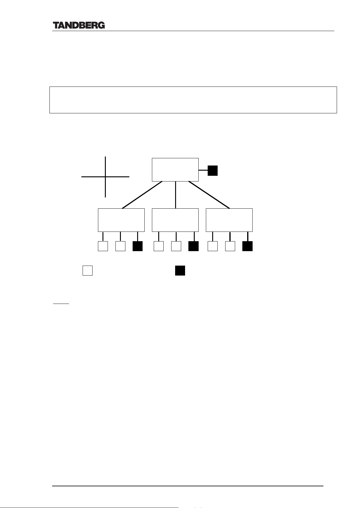
Technical Description of TANDBERG 8000 with software version E3/B8
T
T
T
T
T
T
4.8.1 MultiSite Cascading
The TANDBERG 8000 may be cascaded with other MultiSite systems (up to three) to allow for
up to 10 video sites and 4 audio telephone sites to participate in the same call (i.e. 14 sites in
total).
The cascaded MultiSites may be connected via ISDN or IP.
The ‘host’ MultiSite may be set to Continuous Presence or Voice Switched mode, while the
cascaded MultiSites will be set to Voice Switched as shown below.
Picture
Picture
viewed
viewed
by all
by all
Continuous
X
A
C
B
Host X
Host X
MultiSite
MultiSite
F
F
Continuous
Presence or Voice
Presence or Voice
switched
switched
Cascaded B
Cascaded A
Cascaded A
MultiSite
MultiSite
TF
TF
Cascaded B
MultiSite
MultiSite
F
F
Cascaded C
Cascaded C
MultiSite
MultiSite
F
F
Voice
Voice
switched
switched
Video System using IP
Video System using IP
and/or ISDN
and/or ISDN
Audio call
Audio call
Note:
1. In the above figure ; the ‘Picture viewed by all’ is not relevant for all sites. I.e. if one of
the sites in Cascaded A is ‘on air’, all sites connected to Cascaded A will see the site ‘on
air’ in full picture. The rest of the sites in the conference will see the CP image ‘Picture
viewed by all’.
2. Please, also remember the limitations set by the H.323 standard when considering
cascading of MultiSite systems.
If a site or a cascaded MS is connected on IP, the features Site Naming and
Request/Release Floor is disabled for these particular systems.
D12008 Rev. 11 59
Page 60

Technical Description of TANDBERG 8000 with software version E3/B8
5. Miscellaneous Features
5.1 Multi-language Options
The TANDBERG 8000 supports multiple languages for its on screen menus. The user can select
between the following languages49:
• Chinese
• Chinese (simplified)
• English
• French
• German
• Italian
Note: By pressing the following buttons on the remote control the menu is set to English:
Snapshot – Far End – Snapshot – 0
• Japanese
• Norwegian
• Portuguese
• Russian
• Spanish
• Swedish
5.2 Directory
The TANDBERG 8000 can store up to 516 numbers in the directory.
• 100 in the local directory + 16 for MultiSite entries
• 400 in the global directory (stored in codec’s file system)
The global directory can only be edited through the file system (by using ftp). Once the
global directory file is stored on the codec (ftp://codecIPaddress/user/globdir.prm), these
numbers will appear on the normal directory menu.
Note: The Global Directory numbers may not be edited via the menu nor added into the
MultiSite directory.
5.2.1 MultiSite Entries
For easy set-up of regular MultiSite meetings, the system has 16 MultiSite entries. One needs to
insert the numbers into the local directory first, then put them into a MultiSite entry. When a
MultiSite entry is selected and the connect button is pressed, the system will set up calls to all
the sites for that particular MultiSite entry.
49
Available languages correct at time of printing- additional languages may become available.
D12008 Rev. 11 60
Page 61
Technical Description of TANDBERG 8000 with software version E3/B8
A
B
5.3 Boot up logo
It is possible to customize the boot up logo on the TANDBERG 8000 through the codec’s file
system. The logo file must be in jpg-format and the file size cannot be larger than 704 x 480
pixels50. The color format of the file should be RGB and the file must be stored under
ftp://codecIPaddress/user/startup.jpg. The boot up logo will be shown on screen during boot up,
and may also be displayed when system is not in use (selection in menu).
5.4 Startup scripts
When certain settings- other than default settings- are required on the TANDBERG 8000
system, one can run two customized startup scripts. The scripts can contain a series of Dataport
commands starting with *P (Ref. Dataport Userguide). 20 seconds after reboot of the codec,
these files will be executed in the following order: startup1, globdir, startup2. (See Ch. 5.2 for
more info on the globdir file).
The files should be stored under ftp://codecIPaddress/user/startup1.prm (…/globdir.prm
…/startup2.prm).
Note! Do not put the command *P boot into these files as this will cause the codec to
continuously reboot. (If this is done, ftp into the codec after bootup and delete the file within 10
seconds before its being excecuted).
5.5 Loopback Testing for Remote Diagnostics51
There are two ways of testing network loopback on the TANDBERG 8000.
Request remote loop
A B
Set in local loop
A request is sent to remote side to switch on its loop.
• The local site (A) will see its own video and
hear its own audio
• Remote site (B) will see and hear site (A)
The local system will loop incoming audio and video.
• The local site (A) will see and hear site (B)
• Remote site (B) will see its own video and hear
its own audio
50
Only applicable for E-software (for B8 and earlier: max bootup logo size is 320x200). By opening the jpg-file in a web-browser one may see
the number of pixels of the file (properties)
51
For more diagnostic features on the system, please refer to ‘TANDBERG API – (Dataport User Guide)’ (D11943)
D12008 Rev. 11 61
Page 62

Technical Description of TANDBERG 8000 with software version E3/B8
5.6 Maximum call length
Normally a call will stay up until it is disconnected by the user. The system has the ability to
automatically disconnect the call (incoming or outgoing) after a certain time.
Once a value (1-999 minutes; i.e. up to approximately 17 hours) is inserted in the menu this will
apply for all calls made. Default value is set to zero (i.e. max. call length off).
When the time has expired, the user will be prompted a ‘need for delay?’ message.
5.7 Closed Captioning/Text Chat
The TANDBERG system has the ability to display text on local and far end screens via the
system’s web page. Text chat is supported on both H.320 and H.323 and only in point-to-point
calls. The feature is implemented according to the ITU standard T.140.
T.140 defines a universal presentation-level protocol for text conversation which will work with
all multimedia protocols and with the existing standard for text telephony; V.18. This is
expected to greatly improve the lives of those users reliant on text-based conversation systems,
such as the hearing and speech impaired.
Please, see the User Manual for more information about the usage of this feature.
5.8 Other Standards supported
5.8.1 H.320
This ITU standard is a generic name applied to all standards based videoconferencing
equipment. By its nature it calls up a number of other standards that are designed to perform a
set process to enable the transmission of video, audio and data (i.e. multimedia) across any
synchronous network.
5.8.2 H.323
H.323 is an ITU standard that specifies the operation of real-time audio, video and data
communications over packet based networks. These networks are collectively termed IP
networks and are by nature asynchronous.
5.8.3 H.331 (Broadcast mode)
The TANDBERG system supports the ITU standard H.331 which may be used in special
networks where cost of bandwidth is of great importance, such as Satellite networks.
H.331 provides a broadcast mode where one codec sends only and one (or many) codecs receive
only- thus, no handshaking is done between the codecs.
An essential technical feature in H.331 is that communication channels cannot be two-way
between the information providing terminal and any information receiving terminal because the
path from the receiving terminal to the transmitting one is terminated at the exchange.
H.331 is separate from, but based on H.320 and caters for particular needs of the broadcasting
type multipoint system so that terminals operating for both H.320 and H.331 are easily
implemented.
D12008 Rev. 11 62
Page 63

Technical Description of TANDBERG 8000 with software version E3/B8
5.8.4 H.231/H.243 (MCU control)
When connected to an external MCU (Multi Conference Unit) on ISDN or IP networks, the
TANDBERG system uses the ITU standard H.231 ‘Multipoint control units for audiovisual
systems…’ for MCU controlling features, such as Chair Control and View Site. These features
are easily available by using the colored Quick Keys on the remote control.
The standard H.243 ‘Procedure for establishing communications between three or more audio-
visual terminals..’ is also implemented in the system for MCU connections for both ISDN and
IP with the following functionality:
• Floor request and release
• Site naming and view indication
• MultiSite cascading
• Microphone off indication
• TCS-1 password.
5.8.5 H.243 Password
H.243 password is supported by the system. This feature allows you to have a meeting
password set in the external H.320 or H.323 MCU and the endpoints must then put this
password in to join the meeting. The password must be numerical.
There are two ways of entering this external MCU password:
1) Password entered together with the MCU number
E.g. With MCU number=207987654 and password=1234, the number to dial will be
207987654*1234.
2) Password prompted on screen after the MCU is called
In this case the MCU sends a TCS-1 message to the terminal immediately after the terminal has
called the MCU. When the TANDBERG system receives this message, it will prompt the user
for the password. If password is correct the MCU will join the system to the conference; if not
correct the system will not be connected.
5.8.6 H.281 (FECC)
The ITU standard H.281 is implemented to control the remote site camera and video sources.
The TANDBERG system uses H.281 on both H.320 (Synchronous networks) and H.323
(Asynchronous networks).
5.8.7 KG-194/KIV-7 (NATO encryption)
The TANDERG system supports the NATO encryption standard KG-194.
This requires external cryptographic equipment to be connected between the codec’s NET port
and the network (the same equipment is required at the remote end).
D12008 Rev. 11 63
Page 64

Technical Description of TANDBERG 8000 with software version E3/B8
6. Environmental Issues
6.1 TANDBERG’s Environmental Policy
• TANDBERG’s Research and Development is continuously improving TANDBERG’s
products towards less use of environmentally hazardous components and substances as
well as making the products easier to recycle.
• TANDBERG's products are Video Conferencing Solutions. The idea of Video
Conferencing is to reduce the need for expensive, time demanding and polluting
transport of people. Through people’s use of TANDBERG’s products, the environment
will benefit from less use of polluting transport.
• TANDBERG’s wide use of the concepts of outsourcing makes the company itself a
company with a low rate of emissions and effects on the environment.
• TANDBERG’s policy is to make sure our partners produce our products with minimal
influence on the environment and to demand and audit their compatibility according to
applicable agreements and laws (national and international).
6.2 Environmental Considerations
Like other electronic equipment, the TANDBERG 8000 contains components that may have a
detrimental effect on the environment.
• Printed-wiring boards made of plastic, with flame-retardants like Chloride or Bromide.
• Component soldering that contains lead.
• TV Monitors with phosphorus.
• Smaller components containing substances with possible environmental effect.
After the product’s end of life cycle, it should be returned to authorized waste handling and
should be treated according to National and International Regulations for waste of electronic
equipment.
D12008 Rev. 11 64
Page 65

Technical Description of TANDBERG 8000 with software version E3/B8
7. Product Approvals
The product has been approved by various international approval agencies, among others: UL,
BABT and Nemko. All production of TANDBERG’s equipment is under surveillance of these
agencies different Follow-Up Inspection Schemes for continued compliance.
The test reports and certificates issued by the approval agencies show that the TANDBERG
8000 complies with the following standards.
7.1 Connection of Tele-Terminal Equipment
• CTR 3 w/Amd.1, as specified in Commission Decision 98/515/EC.
TBR 4 (product complies with EU’s Commission Decision 1999/5/EC).
•
7.2 EMC Emission - Radiated Electromagnetic Interference
• EN55022:1994 + A1:1995 + A2:1997 (CISPR 22:1993 + Corr. and Am.1 and Am.2)
Class B. (Product complies with EU’s Commission Decision 89/336/EEC).
• FCC 15 B Class B
7.3 EMC Immunity
• EN 55024:1998
•
EN 61000-3-2:1995 + A12:1995
•
EN 61000-3-3:1995 (product complies with EU’s Commission Decision
89/336/EEC).
7.4 Electrical Safety
• IEC 60950:1991 + Amd.1:1992 + Amd.2:1993 + Amd.3:1995 + Amd.4:1996
•
EN 60950:1992 + Amd.1:1993 + Amd.2:1993 + Amd.3:1995 + Amd.4:1997 +
Amd.11:1997 (product complies with EU’s Commission Decision 73/23/EEC).
•
UL 1950 3. Edition
•
CSA C22.2 No. 950-M95
8. Product Reliability
The predicted reliability of the TANDBERG 8000 is expressed in the expected random Mean
Time Between Failures (MTBF) for the electronic components based on the Power On Hours
(POH).
• The POH for the TANDBERG 8000 Codec is > 69 000 hours
The MTBF value is dependent on correct handling (e.g.: ESD protective measures are used), installation and
use of the TANDBERG 8000.
• The Useful Life Cycle for the TANDBERG 8000 is in excess of 6 years.
• TANDBERG is in a position to identify batches of products with possibly less reliability than
stated above ('product tracking') and will in such an event inform their customers.
• ISO 9001 certificate is available upon request from the manufacturer.
52
.
52
Note: The plasma monitors have expected lifetime (i.e. brightness of the pixels is halved compared to new) of approximately 40 000 hours
D12008 Rev. 11 65
Page 66
Technical Description of TANDBERG 8000 with software version E3/B8
9. Technical specification of TANDBERG 8000
9.1 Mechanical information53
Codec Camera54 Remote Control
Height
Width
Depth
Weight
50” Monitor56 Base* & Monitor- Rack
Height
Width
Depth
Weight
* Footprint of TANDBERG 8000: Width – 86 cm (33.9”) x Depth – 74 cm (29.1”)
• Total weight of TANDBERG 8000 system is approx. 193 kg (426 lbs)
• Total height of the system is: Base&Monitor rack + Camera=172.7 cm (68”)
Standard cables for TANDBERG 8000 Part no. Length
Microphone cable 111021
Natural Audio Amp to speaker cable 111828 0.2 m 0.7 ft
Main Camera cable S-Video (WAVE II)59 112633 2.0 m 6.6 ft
VGA cable (male-male) 111910 5.0 m 16.4 ft
BRI cables (ISDN 1-4) 111757 4.0 m 13.1 ft
BRI cable (ISDN 5) 111890M5 4.0 m 13.1 ft
BRI cable (ISDN 6) 111890M6 4.0 m 13.1 ft
PRI cable 111888 4.0 m 13.1 ft
Ethernet cable 112083 3.0 m 9.8 ft
TANDBERG 8000 Monitor cable 2x (S-Video to
MiniDin Video Cable)
RS232 monitor control cable for T8000
50” Pioneer Plasma screen (9-pin D-SUB)
TANDBERG 8000 VGA cable (dual monitor) 112389 1.5 m 4.9 ft
4.4 cm 1.7 in 12.0 cm 4.7 in 24.5 cm 9.6 in
44.2 cm 17.4 in 13.6 cm 5.3 in 4.5 cm 1.8 in
23.5 cm 9.3 in 14.8 cm 5.8 in 2.1 cm 0.8 in
3.7 kg 8.2 lbs 0.74 kg 1.63 lbs 0.2 kg
55
0.5 lbs52
72 cm 28.3 in 160.7 cm
57
63.3 in
122 cm 48.0 in 253 cm 99.6 in
10 cm 3.9 in 20 cm 7.8 in
41 kg 90.4 lbs 95 kg 210 lbs
54
58
7.5 m 24.6 ft
111816 1.0 m 3.3 ft
112376 1.0 m 3.3 ft
60
53
Monitors, codec and NAM module are placed inside base/rack. All figures are subject to change without any further notice
54
Height: is measured excluding the 3 mm (0.1 in) standard rubber feets. Width: max. 15.6 cm (6.1 in) when fully panned
55
4x AAA 1.5V batteries included
56
TV model is subject to change without any further notice. Two monitors are used in the system
57
This height is measured from floor to top of stand (i.e. the level where the camera is placed). The back cover (in the centre) measures apprx.
2.5 cm (1”) in addition to the stand.
58
Part no. includes microphone
59
Maximum Main Camera cable length supported by TANDBERG is 10m (32,8 ft)
60
Intelligent XGA<->S-Video switching on dual monitor and controlling screen saver on both monitors
D12008 Rev. 11 66
Page 67

Technical Description of TANDBERG 8000 with software version E3/B8
9.2 Packaging
9.2.1 TANDBERG 8000 parcels
TANDBERG 8000 is shipped in three parcels. The following table shows the approximate
measurements of each parcel.
Width 110 cm 137 cm 257 cm
Depth 80 cm 89 cm 83 cm
Height 105 cm 100 cm 33 cm
Weight 90 kg 119 kg 58 kg
(*) The two monitors are placed upright in one box.
Parcel A Parcel B Parcel C
Base
(Incl. Codec, cables etc.)
2 Monitors* Frame
9.3 Operating Temperature and Humidity
• 0° C to 35° C (32° F to 95° F) ambient temperature.
• 10% to 90 % Relative Humidity (RH)
9.4 Storage and Transport Temperature
• -20° C to 60° C (-4° F to 140° F) at RH 10-90 % (non-condensing)
9.5 System Power Consumption
• Maximum power consumption for codec is 65 W.
• Maximum power consumption for the Natural Audio Module is 35 W.
• Power consumption for one monitor is:
• TANDBERG 8000 500 W
D12008 Rev. 11 67
Page 68

Technical Description of TANDBERG 8000 with software version E3/B8
10. Technical specification sheet
System Components
2 x 50" wide screen plasma monitors- (NTSC or PAL),
Wireless remote control, W.A.V.E. camera, microphone, Natural
Audio ModuleTM, integrated cabling and stand
Bandwidth
H.320 up to 2Mbps
H.323 up to 3Mbps
Video Standards
H. 261, H.263, H.263+, H.263++ (Natural VideoTF), H.264
Video Features
Picture in Picture (PIP)
Intelligent Video Management
TF
Video Inputs (5 inputs)
1 x MiniDin, S-video: main camera
1 x MiniDin, S-video: auxiliary/document camera
1 x RCA/Phono, composite: document camera/aux
1 x RCA/Phono, composite: VCR
1 x XGA: PC
Video Outputs (5 outputs)
1 x MiniDin, S-video: main monitor
1 x MiniDin, S-video: dual monitor
1 x RCA/Phono, composite: main monitor or VCR
1 x RCA/Phono, composite: dual monitor or VCR
1 x XGA: main monitor, dual monitor or XGA loop
Video Format
NTSC or PAL
Live Video Resolutions
Native NTSC:
4SIF (704 x 480 pixels), Digital Clarity
Interlaced SIFTF (352 x 480 pixels), Natural Video
SIF (352 x 240 pixels)
Native PAL:
4CIF (704 x 576 pixels), Digital Clarity
Interlaced CIFTF (352 x 576 pixels), Natural Video
CIF (352 x 288 pixels)
QCIF (176 x 144 pixels)
SQCIF (128 x 96 pixels)
Native PC Resolutions:
XGA (1024 x 768 pixels)
SVGA (800 x 600 pixels)
VGA (640 x 480 pixels)
TF
TF
TF
TF
Still Image Transfer
CIF, 4CIF, H.261 Annex D
Audio Standards
G.711, G.722, G.722.1, G.728
Audio Features
Telephone add-on via MultiSiteTF
TANDBERG Natural Audio Module II
Four separate acoustic echo cancellers
Audio mixer
Automatic gain control
Automatic noise reduction
Audio level meters
VCR ducking
TM
D12008 Rev. 11 68
Audio Inputs (6 inputs)
3 x microphone, 24V phantom powered, XLR connector
1 x RCA/Phono, Line Level: audio mixer
1 x RCA/Phono, Line Level: auxiliary
1 x RCA/Phono, Line Level: VCR
Audio Outputs (3 outputs)
1 x RCA/Phono, Line Level: main audio
1 x RCA/Phono, Line Level: auxiliary
1 x RCA/Phono, Line Level: VCR
XGA Input / Output
Input: 640 x 480 – 1024 x 768, 56 - 85 Hz. auto-detection
Output: 640 x 480 – 1024 x 768, 60 Hz
Frame Rates – Point to Point & MultiSiteTF
15 frames per second @ 56 - 128kbps
30 frames per second @ 168kbps - 3Mbps
60 fields per second @ 448kbps - 3Mbps (Natural Video
TF
)
MultiSiteTF Features
ISDN & IP DownspeedingTF at call set-up
Dial in / Dial out capabilities
Continuous Presence or Voice Switched
Chair control for host system
5 sites including min. 1 telephone call
4 sites including min. 1 IP telephone call
Built-in MultiSite
Built-in MultiSite
Duo Video
MultiSite
4 sites @ 64-768kbps + 1 telephone call over ISDN
3 sites @ 64-1Mbps + 2 telephone calls over ISDN
Point-to point @ 3Mbps + 3 telephone calls via ISDN
MultiSite
4 sites @ 56 - 512 (384)kbps + 1 telephone call via ISDN
3 sites @ 56 - 768 (512)kbps + 2 telephone calls via ISDN
Point-to point @ 56 - 1.5 (1)Mbps + 3 telephone calls via ISDN
MultiSite
4 sites @ 256kbps or 3 sites @ 384kbps
4 sites @ 56 - 192kbps + 1 telephone call via ISDN
3 sites @ 56 - 256kbps + 2 telephone calls via ISDN
Point-to-point @ 56 - 512 kbps + 3 telephone calls via ISDN
MultiSiteTF (H.243) Cascading
Up to 10 video sites @ 768kbps + 4 audio sites
Any combination of IP & ISDN connections (transcoding)
Combination of V.35 & IP connections (transcoding)
TF
audio bridge for up to 5 sites
TF
IP audio bridge for up to 4 sites
TF
, Digital ClarityTF
TF
over IP
TF
over ISDN PRI / E1(T1)
TF
over ISDN / 6BRI
Page 69

Technical Description of TANDBERG 8000 with software version E3/B8
Duo VideoTF
Available on all networks
Available in MultiSiteTF (over IP & ISDN)
Available on dual and single monitor systems
Network Features
Auto H.320/H.323 dialing
Downspeeding
Programmable network profiles
Password protection
Intelligent Call Management
Maximum call length
Ho on ISDN-PRI Facility
NATO standard KG194/KIV-7 encryptor support
Automatic SPID and line number configuration (National ISDN,
GR-2941-CORE)
SoftMuxTF
H.331 Broadcast Mode
TF
TF
Embedded Encryption
H.320 and H.323 point-to-point calls (128 bit key AES or 56 bit
key DES)
Standards-based: H.233, H.234, H.235, DES, AES
Automatic key generation and exchange
Supported in DuoVideo and MultiSite
H.323 Network Features
Resource Reservation Protocol (RSVP)
IP precedence (QoS)
DiffServ (QoS)
IP type of service (TOS)
Network Address Translation (NAT) support
IP adaptive bandwidth management (including flow control)
Auto gatekeeper discovery
Dynamic playout and lypsync buffering
Intelligent Packet Loss Recovery
TF
(IPLR)
Security Features
IP Administration password
Access code
Menu Password
Streaming password
H.243 MCU password
VNC password
Authentication of remote management system via MD5
Network Interfaces
6 x ISDN BRI (RJ-45), S-interface
1 x E1/T1 G.703 (RJ-45) for ISDN PRI or Leased E1/T1
1 x E1/T1 G.703 (RJ-45) for ISDN PRI cascading
1 x LAN/Ethernet (RJ-45) 10/100 Mbit (LAN/DSL/cable modem)
1 x X.21 / V.35 / RS-449 with RS-366 dialing, Leased Line, data
triggered mode, manual mode, auto mode
Ethernet / Internet / Intranet Connectivity
TCP/IP, DHCP, ARP, FTP, Telnet, HTTP
SNMP Enterprise Management
Internal web server
Internal streaming server
10/100Mbit full/half duplex (manual or auto detect selection)
IP conflict warning
Other Supported ITU Standards
H.320, H.323, H.281, BONDING (ISO 13871), H.231, H.243,
H.331
W.A.V.E. II (Wide Angle View) camera
10 x zoom
1/3" CCD
35° Tilt +61°
190° PAN +77°
76° vertical field of view
270° horizontal field of view
450 (PAL) / 460 (NTSC) horizontal TV lines
Min. illumination 7 Lux (F1.8)
Auto or manual focus, brightness and white balance
Far end camera control
15 near and far-end camera pre-sets
Voice-activated camera positioning
Up to 4 camera daisy chain supports
VISCA camera support
Presentations and Collaboration
Natural Presenter Package including:
PC Presenter
PC SoftPresenter
Digital Clarity
Duo Video
T.120 Microsoft NetMeeting support via RS-232 (9-pin D-sub)
Streaming (compatible with Cisco IP/TV, Apple QuickTime and
RealPlayer v8 etc.)
TF
TF
TF
TF
Closed Captioning/Text Chat
T.140 standards-based
System Management
Total management via embedded web browser, SNMP, Telnet and
FTP
Remote software upload: during a call over all networks, via
webserver, and via FTP server
1 x RS-232 used for main camera control
1 x RS-232 for local software upgrades, local control and
diagnostics
Remote control and menu system
Support for the TANDBERG Management Suite
Authentication of remote management system via MD5
Directory Services
400 number global directory
100 number local directory including:
16 dedicated MultiSite
TF
entries
11 selectable menu languages:
Chinese, English, French, German, Italian, Japanese, Norwegian,
Portuguese, Russian, Spanish and Swedish
Customized boot up logo (jpeg)
Power
Auto-sensing power supply
100 - 250V AC, 50 - 60 Hz
65 watts max. for codec and main camera
D12008 Rev. 11 69
 Loading...