

TKO 3R Assembly Manual


2
IMPORTANT SAFETY INSTRUCTIONS
• Read this Owner’s Manual and follow it’s instructions carefully before using the
machine. Make sure that it is properly assembled and tightened before each
use.
• Inspect your machine prior to exercise to ensure that all nuts and bolts are fully
tightened.
• Replace the worn parts immediately.
• Most exercise equipment is not recommended for small children. Children
should not use the machine unless they are under adult supervision.
• Exercise equipment has moving parts. In the interest of safety, keep others,
especially children and pets, at a safe distance while exercising.
• Warm up 5 to 10 minutes before each workout and cool down 5 to 10 minutes
afterward. Never hold your breath while exercising.
• Rest adequately between workouts. Muscles tone and develop during these
rest periods. Beginners should work out twice a week and increase gradually to
4 to 5 times per week.
• Remove all jewelry, including rings, chains and pins before commencing exercise.
• Never exercise in bare feet or socks, always wear correct footwear, such as running,
walking, or cross-training shoes.
• Always wear suitable clothing and footwear during exercise. Do NOT wear loose
fitting clothing that could become entangled with the moving parts of your
exercise machine.
MEDICAL WARNING
• Before beginning any exercise program, consult your personal physician.
Evaluate your present fitness level and determine the exercise program that
is most appropriate for your particular age and condition.
• If you experience any pain or tightness in your chest, irregular heartbeats,
shortness of breath, faintness or other unusual discomfort while exercising,
stop and consult your physician before continuing.
Maximum recommended exercise weights not to exceed 270Lbs (123Kgs)

3
TKO Fitness products are designed and manufactured to the highest
standards in order to provide you with years of great workouts. We
proudly stand behind all our products with the best customer service in
the fitness industry. If you have any question or need assistance please
contact us at:
Customer Service: customerservice@tko.com
Toll free: 866-856-3488 or 713-895-9270
Monday-Friday 8:30am to 4:30pm CT
4
BEFORE YOU BEGIN
Note: Before starting assembly remove all parts and hardware from the
carton, ensure you have everything according to the list.
TOOLS YOU NEED (Included)
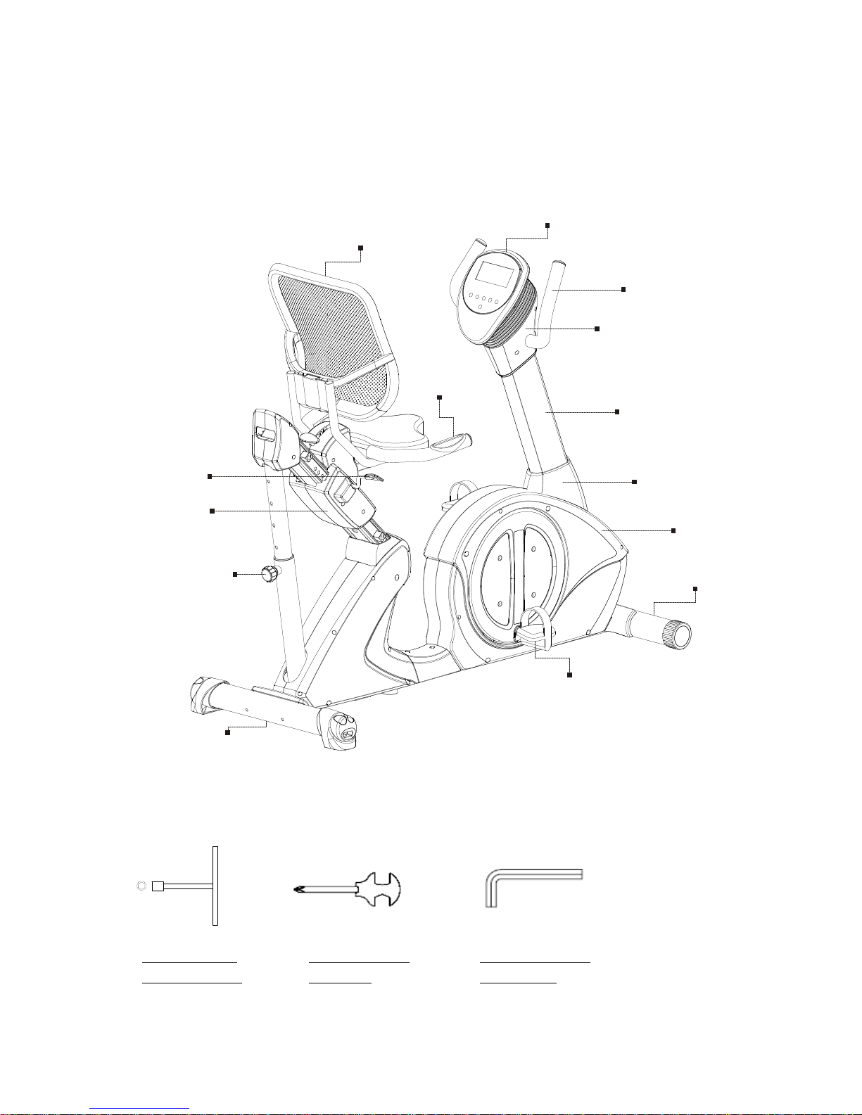
ALLEN WRENCH
(5 & 6 mm)
Display Console
HEX WRENCH
(17mm x 2
Handlebar
Backrest
(Mesh style)
Console Sleeve
Hand Grip Pulse
Upright Post
Upright Bottom
Seat Adjustment Pull
Handle
Main Frame
Front Stabilizer
Foot Pedal
Seat Carriage
Knob
Rear Stabilizer
COMBINATION
WRENCH
5
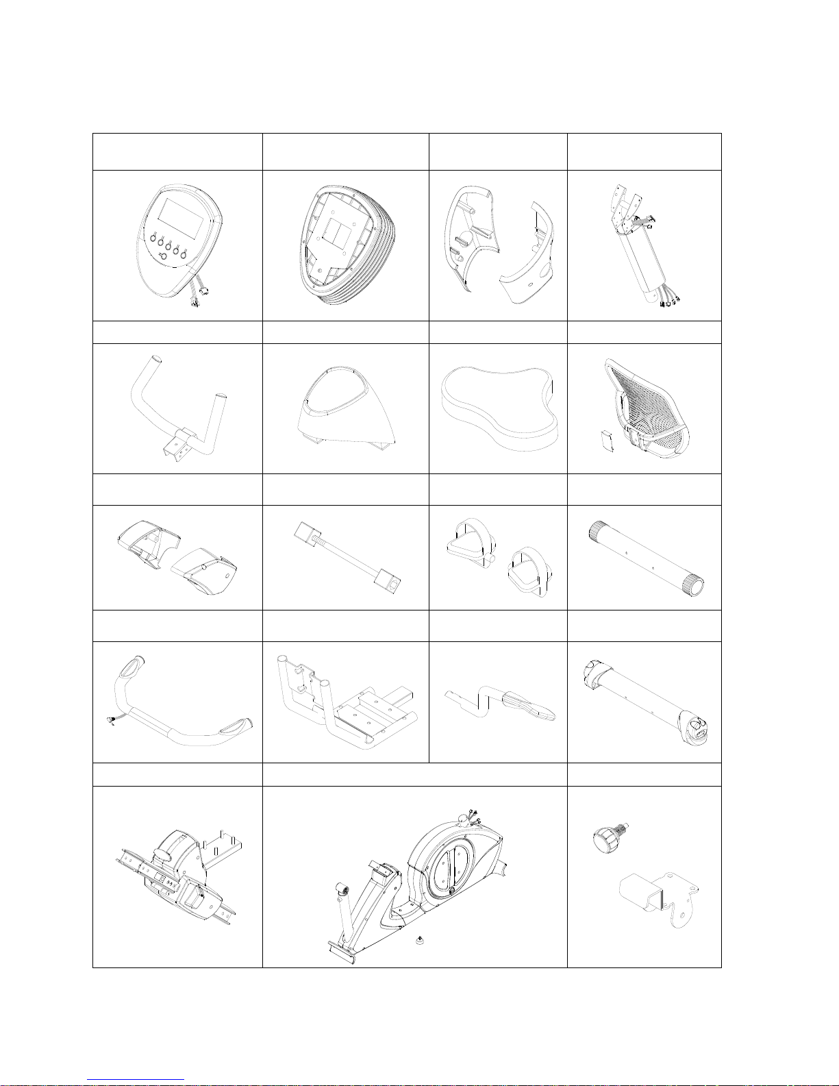
LIST OF COMPONENTS
Display Console
Console Bottom Sleeve
Console Bottom
Sleeve Cover
Upright Post
Assembly
Handlebar
Upright Bottom Cover
Seat Cushion
Backrest Assembly
Seat Rail Cover
Rubber Stopper
Assembly
Foot Pedals
Front Stabilizer
Seat Handlebar
Assembly
Seat Frame
Seat Adjustment
Pull Handle
Rear Stabilizer
Seat Carriage Assembly
Main Frame Assembly
Lock Pin & Bracket

6
HARDWARE PACK
There are 3 separate hardware pack in the carton (A, B & C)
Assembly step 1: Hardware Pack A
Assembly step 3, 4 & 5: Hardware Pack B
Assembly step 7 to 11: Hardware Pack C
Hardware pack A - Assembly step 1
Part #
Description
Q’TY
88
Lock Washer (M8)
4
90
Flat Washer (8mm x 16mm x 2.0mm t)
4
115
Bolt, Socket Head (M8 x p1.25 x 90mm L)
4
Hardware pack B - Assembly step 3, 4 & 5
Part #
Description
Q’TY
88
Lock Washer (M8)
5
90
Flat Washer (8mm x 16mm x 2.0 t)
5
97
Screw, Pan Head (M5 x p0.8 x 25mm L)
4
99
Screw, Round Head (M5 x p0.8 x 15mm L)
4
111
Bolt, Socket Head (M6 x p1.0 x 15mm L)
4
112
Bolt, Socket Head (M8 x p1.25 x 16mm L)
4
114
Bolt, Socket Head (M8 x p1.25 x 55mm L)
1
Hardware pack C - Assembly step 7 to11
Part #
Description
Q’TY
87
Lock Washer (M5)
2
88
Lock Washer (M8)
10
90
Flat Washer (8mm x 16mm x 2.0 t)
10
93
Self-Tapping Screw, Truss Head (M4 x 16mm L)
1
99
Screw, Round Head (M5 x p0.8 x 15mm L)
2
107
Carriage Bolt (M8 x p1.25 x 50mm L)
2
112
Bolt, Socket Head (M8 x p1.25 x 16mm L)
10
113
Bolt, Socket Head (M8 x p1.25 x 40mm L)
4
119
Bolt, Hex Head (M10 x p1.5 x 90mm L)
1
127
Lock Nut (M8 x p1.25)
2
128
Lock Nut (M10 x p1.5)
1
150
Nylon coated Screw, Round Head (M5 x p0.8 x 15mm L)
2
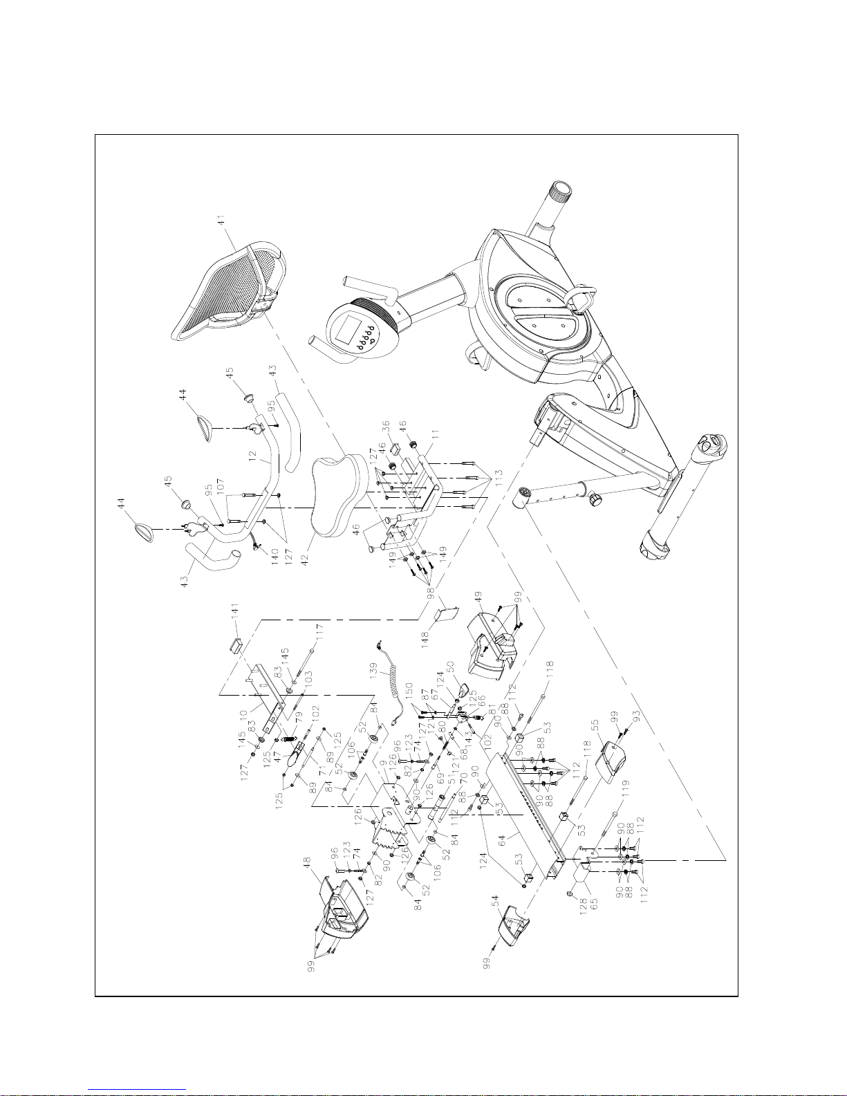
7
EXPLODED DIAGRAM (A)
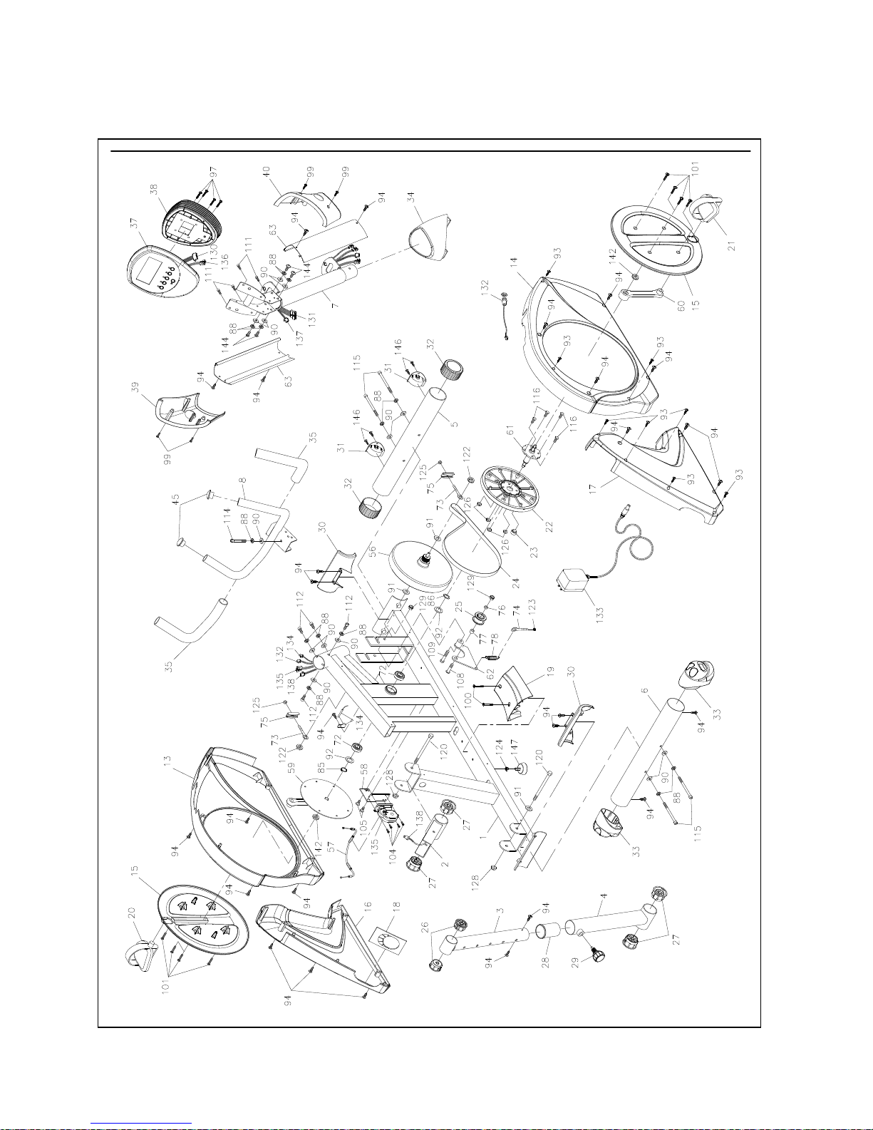
8
EXPLODED DIAGRAM (B)
!

9
PARTS LIST
NO.
Item Name
Q'TY
1
Main Frame
1
2
Seat Rail Support Bracket (front)
1
3
Seat angle adjustment upper tube
1
4
Seat angle adjustment lower tube
1
5
Front Stabilizer
1
6
Rear Stabilizer
1
7
Upright Post
1
8
Handlebar
1
9
Seat Carriage
1
10
Seat Frame Support
1
11
Seat Frame
1
12
Seat Handlebar
1
13
Chain Cover (Left Front)
1
14
Chain Cover (Right Front)
1
15
Crank Disk (L&R)
2
16
Chain Cover (Left Rear)
1
17
Chain Cover (Right Rear)
1
18
Decoration Cover for Angle Adjustment Lower Tube
1
19
Base Center Cover
1
20
Left foot Pedal
1
21
Right foot Pedal
1
22
Pulley (Sprocket)
1
23
Magnet
1
24
Drive Belt
1
25
Compression Wheel
1
26
Bushing (ψ50.8xψ10) (For Part 3)
2
27
Bushing (ψ60xψ10) (For Part 2 & 4)
4
28
Plastic Sleeve (For Part 4)
1
29
Spring Loaded Lock Pin
1
30
Decorative Cover (For Front & Rear Stabilizer)
2
31
Transport Wheel (L&R)
2
32
Front Stabilizer End Cap
2
33
Rear Stabilizer End Cap
2
 Loading...