

Page 1

Page 2

2
IMPORTANT SAFETY INSTRUCTIONS
• Read this Owner’s Manual and follow it’s instructions carefully before using the
machine. Make sure that it is properly assembled and tightened before each
use.
• Inspect your machine prior to exercise to ensure that all nuts and bolts are fully
tightened.
• Replace the worn parts immediately.
• Most exercise equipment is not recommended for small children. Children
should not use the machine unless they are under adult supervision.
• Exercise equipment has moving parts. In the interest of safety, keep others,
especially children and pets, at a safe distance while exercising.
• Warm up 5 to 10 minutes before each workout and cool down 5 to 10 minutes
afterward. Never hold your breath while exercising.
• Rest adequately between workouts. Muscles tone and develop during these
rest periods. Beginners should work out twice a week and increase gradually to
4 to 5 times per week.
• Remove all jewelry, including rings, chains and pins before commencing exercise.
• Never exercise in bare feet or socks, always wear correct footwear, such as running,
walking, or cross-training shoes.
• Always wear suitable clothing and footwear during exercise. Do NOT wear loose
fitting clothing that could become entangled with the moving parts of your
exercise machine.
MEDICAL WARNING
• Before beginning any exercise program, consult your personal physician.
Evaluate your present fitness level and determine the exercise program that
is most appropriate for your particular age and condition.
• If you experience any pain or tightness in your chest, irregular heartbeats,
shortness of breath, faintness or other unusual discomfort while exercising,
stop and consult your physician before continuing.
Maximum recommended exercise weights not to exceed 270Lbs (123Kgs)
Page 3

3
TKO Fitness products are designed and manufactured to the highest
standards in order to provide you with years of great workouts. We
proudly stand behind all our products with the best customer service in
the fitness industry. If you have any question or need assistance please
contact us at:
Customer Service: [email protected]
Toll free: 866-856-3488 or 713-895-9270
Monday-Friday 8:30am to 4:30pm CT
Page 4
4
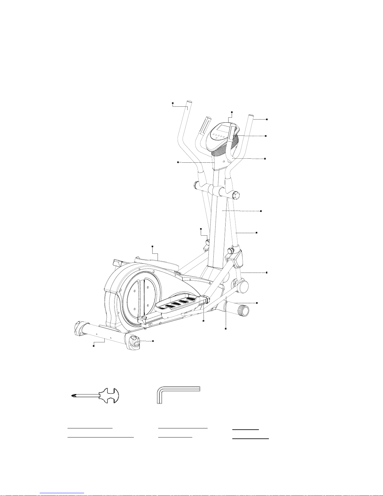
BEFORE YOU BEGIN
Note: Before starting assembly remove all parts and hardware from the
carton, ensure you have everything according to the list.
TOOLS YOU NEED (Included)
ALLEN WRENCH
(5 & 6 mm)
COMBINATION
WRENCH (13 &
Display
Console Sleeve
Upright Post
Pivoting Arm
Telescoping
Pull Pin
Front Stabilizer
Non-Slip Foot Pad
Height Adjustable End Cap
Rail
Rear Stabilizer
Hand Grip Pulse Sensor
Fixed Handlebar
Right Handlebar
Pedal Link Arm
Left Handlebar
WRENCH
(10 & 17 mm)
Page 5

5
LIST OF COMPONENTS
Display Console
Console Bottom
Sleeve
Console Bottom
Sleeve Cover
Upright Post Assembly
Fixed Handlebar
Handlebar
Upright Cover
Pedal Support Arm Assembly
Handrail Base
Cover
Pivoting Arm Cover
Rail Cap
Main Frame Assembly
Front Stabilizer
Rear Stabilizer
Non-Slip Foot Pads
Stand
Page 6
6
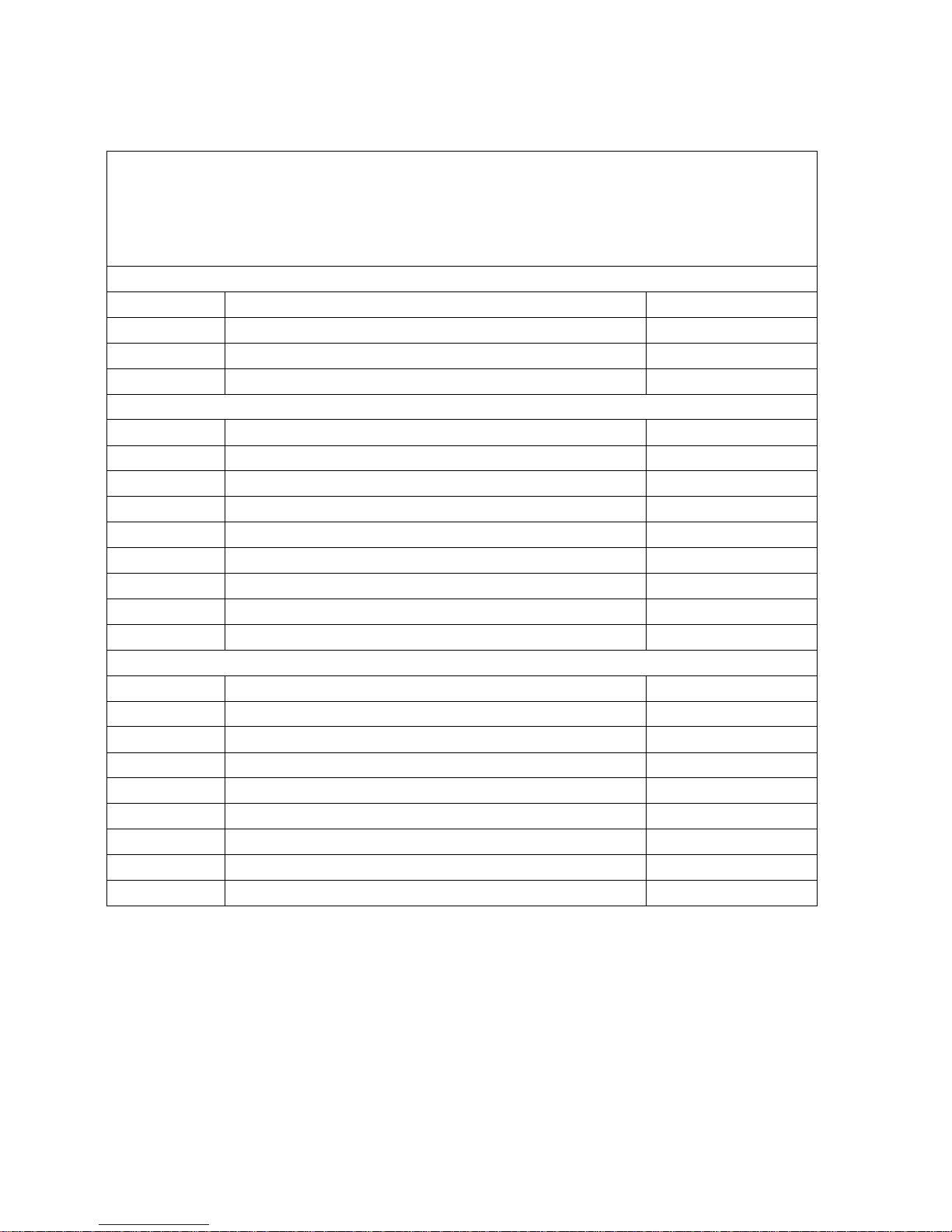
HARDWARE PACK
There are 3 separate hardware pack in the carton (A, B & C)
Assembly step 1: Hardware Pack A
Assembly step 2 to 5: Hardware Pack B
Assembly step 6 to 9: Hardware Pack C
Hardware pack A - Assembly step 1
Part #
Description
Q’TY
79
Lock Washer (M8)
4
80
Flat Washer (8mm x 16mm x 2.0mm t)
4
105
Bolt, Socket Head (M8 x p1.25 x 90mm L)
4
Hardware pack B - Assembly step 2 - 5
Part #
Description
Q’TY
79
Lock Washer (M8)
4
88
Self-Tapping Screw, Flat Head (M4x16mm)
10
93
Screw, Round Head (M5 x p0.8 x 16mm L)
4
98
Bolt, Button Head (M8 x p1.25 x 90mm L)
4
99
Bolt, Button Head (M10 x p1.25 x 85mm L)
2
109
Nut (M8)
4
111
Nut (M10)
2
122
Flat Washer (10mm x 28mm x 2.0 t)
2
Hardware pack C - Assembly step 6 to9
Part #
Description
Q’TY
79
Lock Washer (M8)
1
80
Washer (8mm x16mm x 2.0mm t.)
1
90
Screw, Pan Head (M5 x p0.8 x 25mm L)
4
91
Screw, Round Head (M5 x p0.8 x 15mm L)
4
101
Bolt, Socket Head (M6 x p1.0 x 15mm L)
4
102
Bolt, Socket Head (M6 x p1.0 x 35mm L)
4
104
Bolt, Socket Head (M8 x p1.25 x 55mm L)
1
108
Nut (M6)
4
Page 7
7
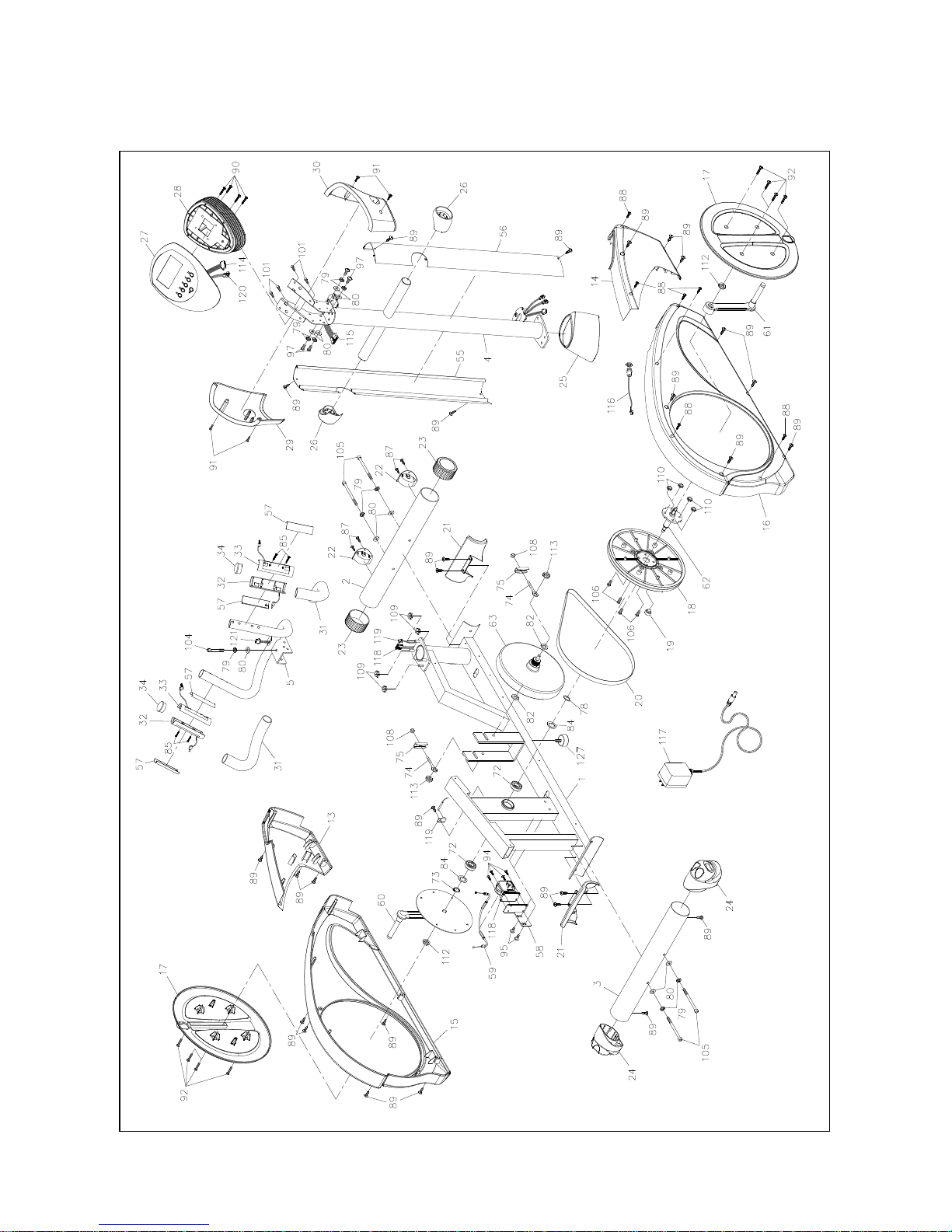
EXPLODED DIAGRAM (A)
Page 8
8
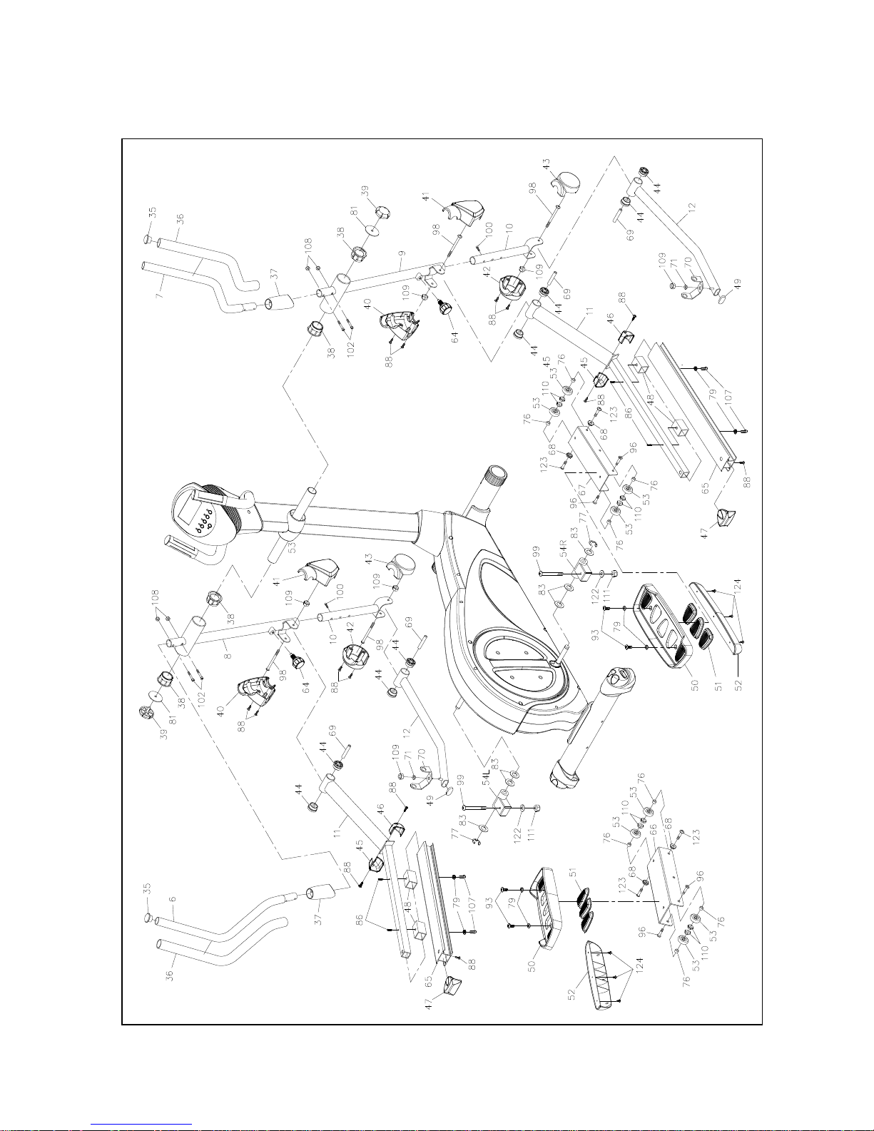
EXPLODED DIAGRAM (B)
Page 9
9
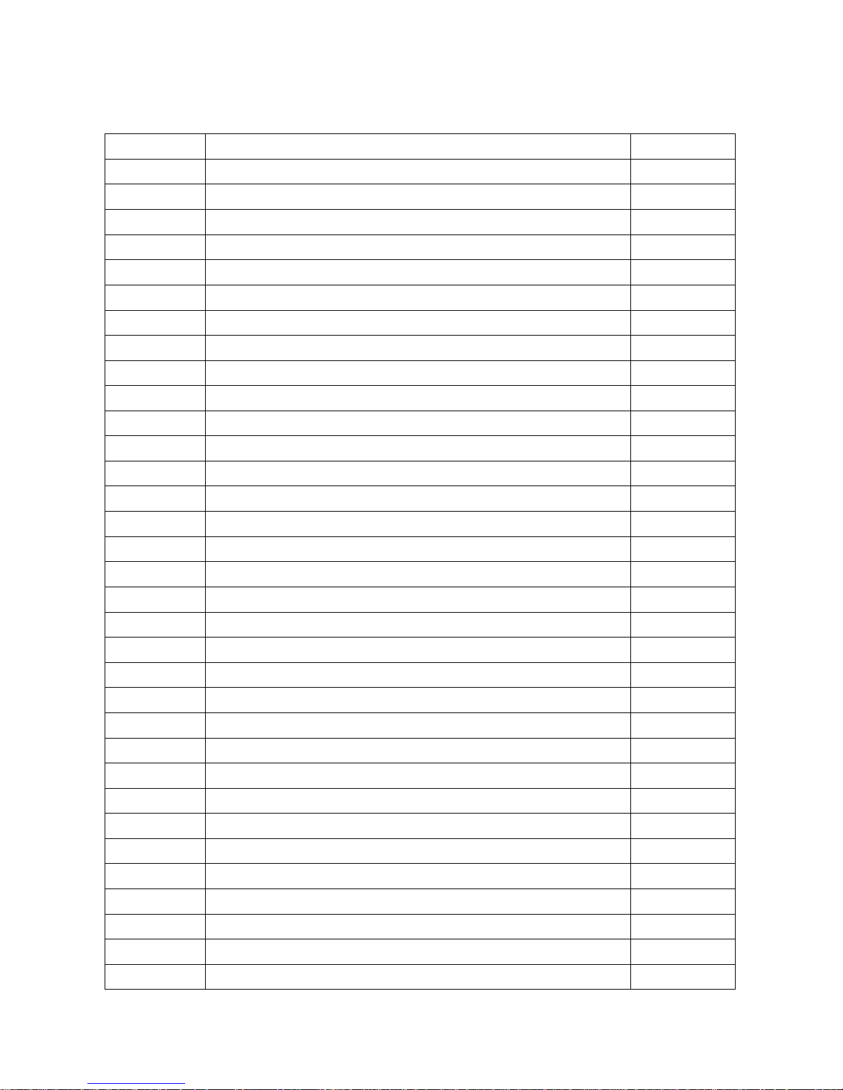
PARTS LIST
NO.
Item Name
Q'TY
1
Main Frame
1
2
Front Stabilizer
1
3
Rear Stabilizer
1
4
Upright Post
1
5
Fixed Handlebar
1
6
Handlebar (Left)
1
7
Handlebar (Right)
1
8
Pivot Arm (Left)
1
9
Pivot Arm (Right)
1
10
Lower Pivot Arm
2
11
Pedal Support Arm
2
12
Lower Pedal Support Arm
2
13
Base Frame Shroud (Left)
1
14
Base Frame Shroud (Right)
1
15
Flywheel Shroud (Left)
1
16
Flywheel Shroud (Right)
1
17
Crank Disk (L&R)
2
18
Pulley
1
19
Magnet
1
20
Drive Belt (1244mm J6)
1
21
Front & Rear Stabilizer Decorative Cover
2
22
Transport Wheel (L&R)
2
23
Front Stabilizer End Cap
2
24
Rear Stabilizer End Cap
2
25
Upright Sleeve
1
26
Rotator Cuff – Pivoting Arm
2
27
Display Console
1
28
Console Bottom Sleeve
1
29
Console Bottom Sleeve Cover (Left)
1
30
Console Bottom Sleeve Cover (Right)
1
31
Foam Grip for (For Fixed Handlebar)
2
32
Hand Grip Pulse Sensor
2
33
Hand Grip Pulse Bottom Sensor
2
Page 10
10
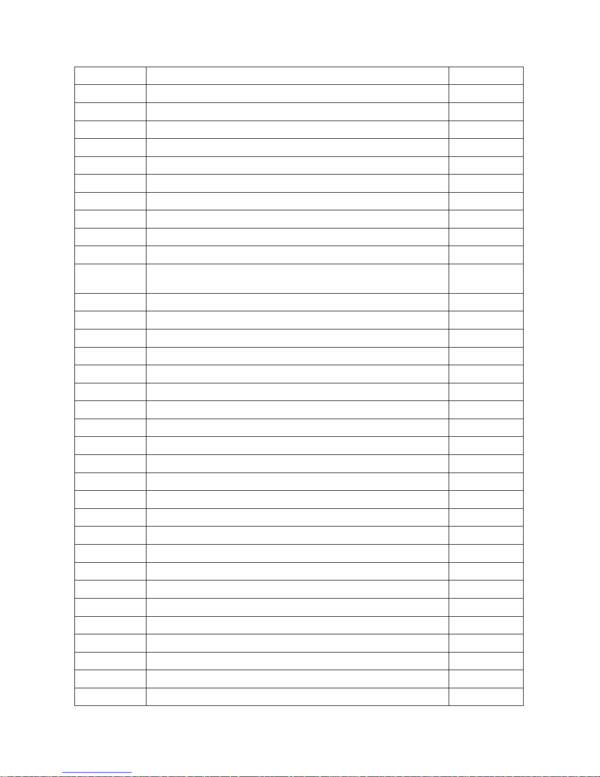
NO.
Item Name
Q'TY
34
Round Plug (31.8mm) (For Handlebar #5)
2
35
Round Plug (For Part #6 & 7)
2
36
Foam Grip for Handlebar (For Part #6 & 7)
2
37
Handlebar Sleeve
2
38
Pivot Arm Bushing (ψ60mm)
4
39
Round End Cap (ψ60mm)
2
40
Pivot Arm Bottom Cover (Left)
2
41
Pivot Arm Bottom Cover (Right)
2
42
Lower Pivot Arm Cover (Left)
2
43
Lower Pivot Arm Cover (Right)
2
44
Plastic Bushing (ψ12.1xψ38mm) (For Peddle Support
Arm)
8
45
Rail Cover (Left)
2
46
Rail Cover (Right)
2
47
Rail End Cap
2
48
Aluminum Rail Inner Sleeve
4
49
Oval Plug (20mmx40mm) (For Part #12)
2
50
Foot Pedal
2
51
Foot Pedal Non-Slip Pad
6
52
Pedal Bottom Support
2
53
Rollers
8
54L
Left Rail Connector
1
54R
Right Rail Connector
1
55
Upright Post Left Side Cover
1
56
Upright Post Right Side Cover
1
57
Pulse Sensor Metal Plate
4
58
Tension Control Motor Mounting Bracket
1
59
Tension Cable
1
60
Left Crank
1
61
Right Crank
1
62
Axle (For Crank)
1
63
Flywheel
1
64
Spring Loaded Lock Pin
2
65
Aluminum Rail
2
66
Foot Pedal Slider
1
Page 11
11
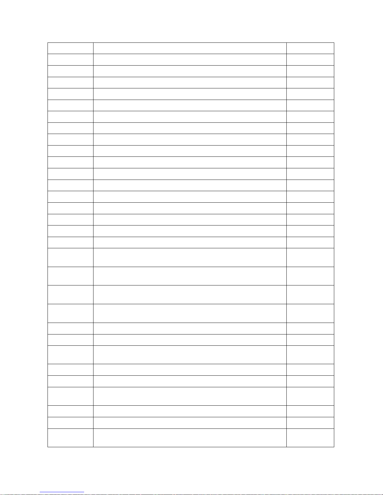
NO.
Item Name
Q'TY
68
Spacer for Rollers
4
69
Sleeve (8.2x12x7.4mm) (For Pedal Support Arm)
4
70
U-Shaped Bracket
2
71
Spacer
2
72
Bearing (6004Z)
2
73
C-Ring (20mm)
1
74
Eye Bolt (For Flywheel)
2
75
Metal Bracket (For Flywheel)
2
76
Roller Spacer (8x12x7.5mm) (For Part #53)
8
77
E-Ring (For Part #54R & 54L)
2
78
Wave Washer (For Part #62)
1
79
Lock Washer (M8)
19
80
Washer (8x16x2.0t)
9
81
Washer (8x60x2.0t) (For Part #8 & 9)
2
82
Washer (10x23x2.0t) (For Flywheel)
2
83
Washer (17x33.4x1.0t) (For Part #54R & 54L)
6
84
Washer (21x30x1.0t) (For Part #62)
2
85
Self-Tapping Screw, Round Head (M3x25mm)(For Pulse
Sensor)
4
86
Self-Tapping Screw, Truss Head (M4x20mm) (For Part
#65)
4
87
Self-Tapping Screw, Button Head (M4x16mm) (For Part
#22)
4
88
Self-Tapping Screw, Flat Head (M4x16mm)(FOR
PART#45 & 46)
24
89
Self-Tapping Screw, Flat Head (M5x18mm)
27
90
Screw, Pan Head (M5xp0.8x25mm) (For Display Console)
4
91
Screw, Round Head (M5xp0.8x15mm) (For Part# 29 &
30)
4
92
Screw, Round Head (M6xp1.0x15mm) (For Part# 17)
8
93
Screw, Round Head (M8xp1.25x16mm) (For Foot Pads)
4
94
Screw, Flat Head (M5xp0.8x12mm) (For Tension Control
Motor)
4
95
Bolt, Pan Head (M8xp1.25x15mm) (For Part #58)
2
96
Bolt, Pan Head (M8xp1.25x25mm) (For Part #53)
4
97
Bolt, Button Head (M8xp1.25x16mm) (For Fixed
Handlebar)
4
Page 12
12
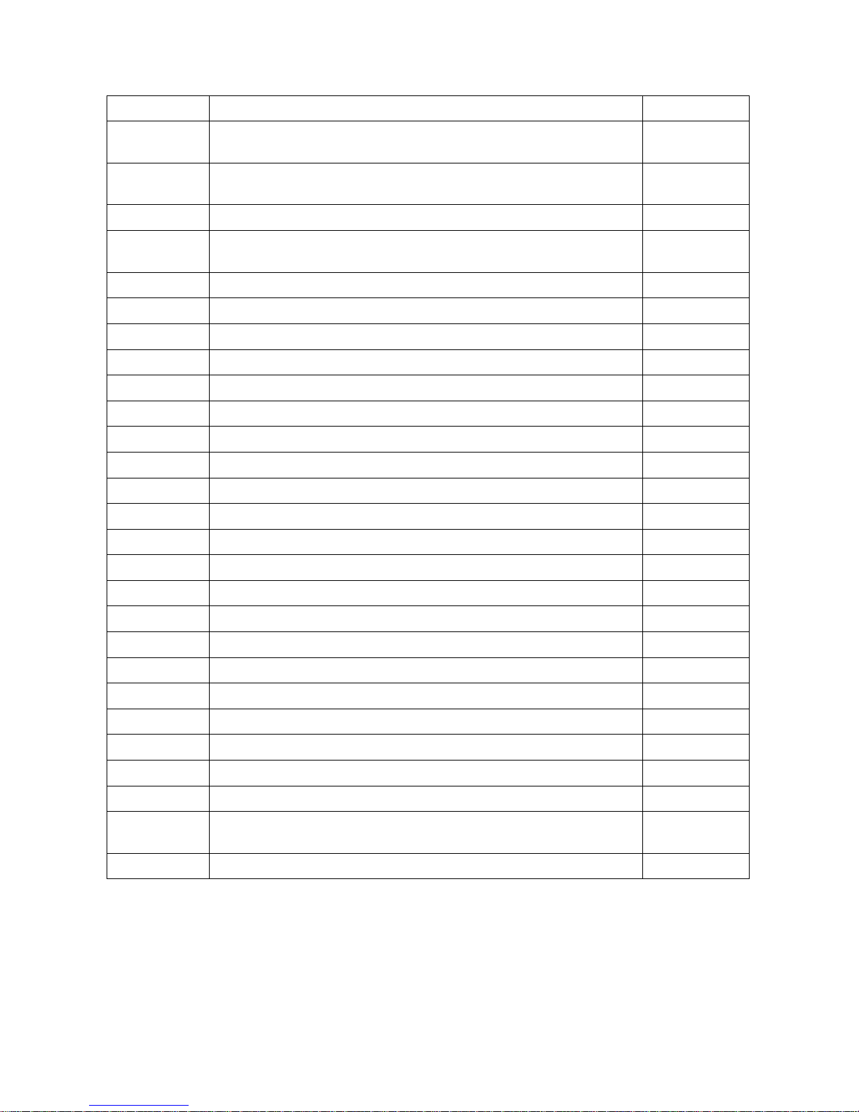
NO.
Item Name
Q'TY
98
Bolt, Button Head (M8xp1.25x90mm) (For Part #11 &
12)
4
99
Bolt, Button Head (M10xp1.25x85mm) (For Part #54R &
54L)
2
100
Bolt, Socket Head (M5xp0.8x15mm) (For Part #10)
2
101
Bolt, Socket Head (M6xp1.0x15mm) (For Display Console
Assy)
4
NO.
Item Name
Q'TY
102
Bolt, Socket Head (M6xp1.0x35mm) (For Part #8 & 9)
4
104
Bolt, Socket Head (M8xp1.25x55mm)
1
105
Bolt, Socket Head (M8xp1.25x90mm) (For Part #2 & 3)
4
106
Bolt, Hex Head (Thin) (M8xp1.25x16mm) (For Part #18)
4
107
Bolt, Hex Head (M8xp1.25x16mm) (For Part65)
4
108
Nut (M6) (For Part 8 & 9)
6
109
Nut (M8)
10
110
Thin Nylon Lock Nut (M8) (For Part #53)
12
111
Nut (M10) (For Part #54R & 54L)
2
112
Flange Nut (M10) (For Crank)
2
113
Flange Nut – Black Color (M10)
2
114
Display Console Cable
1
115
Display Console Extension Cable (Inside Upright Post)
1
116
Power Extension Cable
1
117
AC Adaptor
1
118
Tension Control Motor
1
119
Speed Sensor Cable
1
120
Pulse Grip Sensor Cable
1
121
Pulse Grip Sensor Extension Cable (Inside Upright Post)
1
122
Washer (10x28x2.0t) (For Part #54R & 54L)
2
123
Flat-head inner hexagon screw (M8xp1.25x33mm) (For
Rollers)
4
124
Self-Tapping Screw, Flat Head (M4x10mm) (For Part #52)
6
Page 13
13
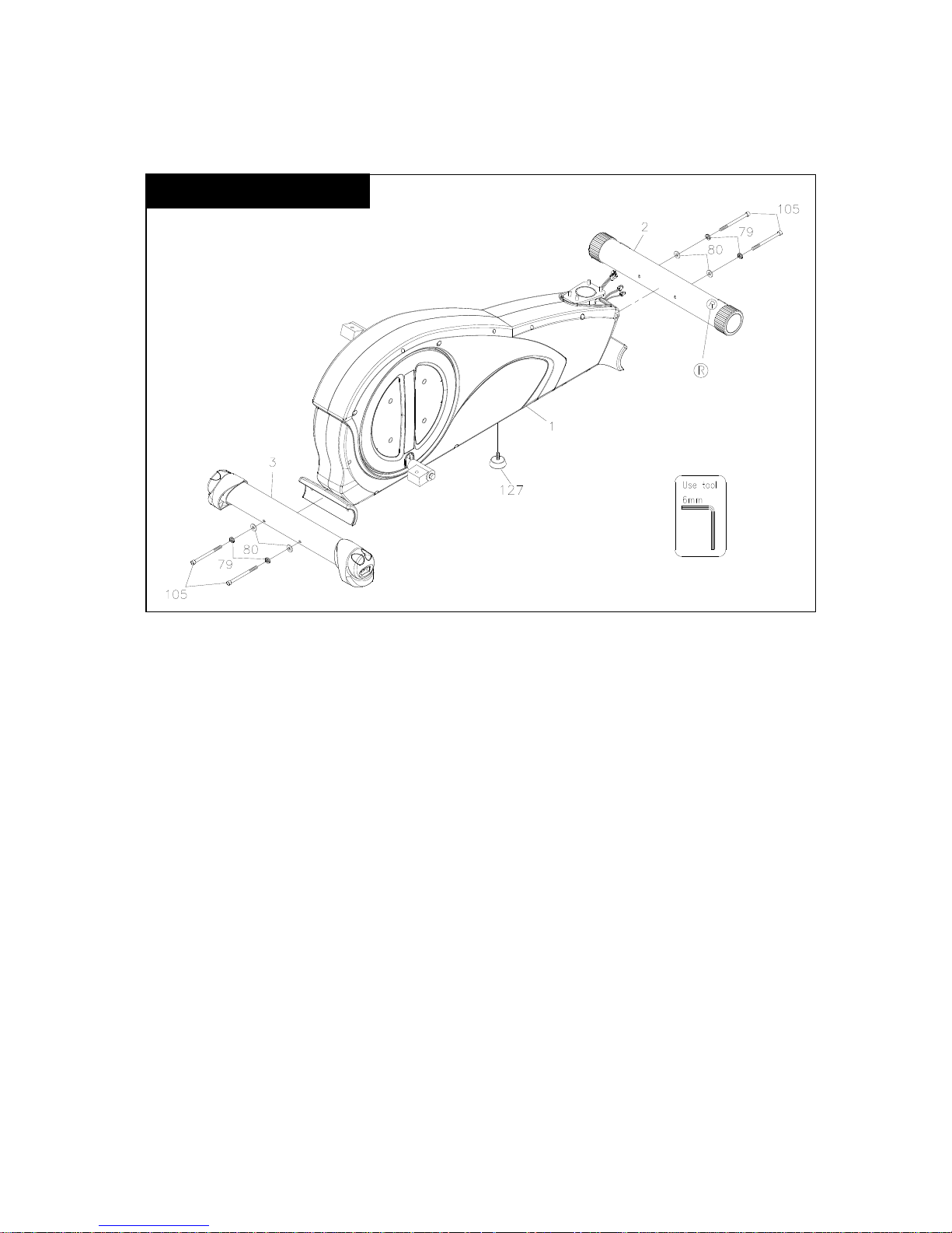
ASSEMBLY INSTRUCTIONS
STEP 1 – Base Stabilizer
a. Attached the Front Stabilizer (2) to the Main Frame (1). A circular decal (“R”)
should be located on the right side of the Front Stabilizer (2).
b. Secure it using 2 Lock Washers (M8) (79), 2 Regular Washers (8x16x2.0t)(80)
and 2 Bolts, Socket Head (M8xp1.25x90mm) (105).
c. DO NOT tighten these bolts yet.
d. Attached the Rear Stabilizer (3) to the Main Frame (1) using 2 Lock Washers
(M8) (79), 2 Regular Washers (8x16x2.0t) (80) and 2 Bolts, Socket Head
(M8xp1.25x90mm) (105).
e. Securely tighten these 4 Bolts with Wrenches.
f. Install the Floor Leveler (127) to the bottom Middle of the Main Frame Assembly.
Adjust it accordingly.
USE HARDWARE KIT A
Page 14
14
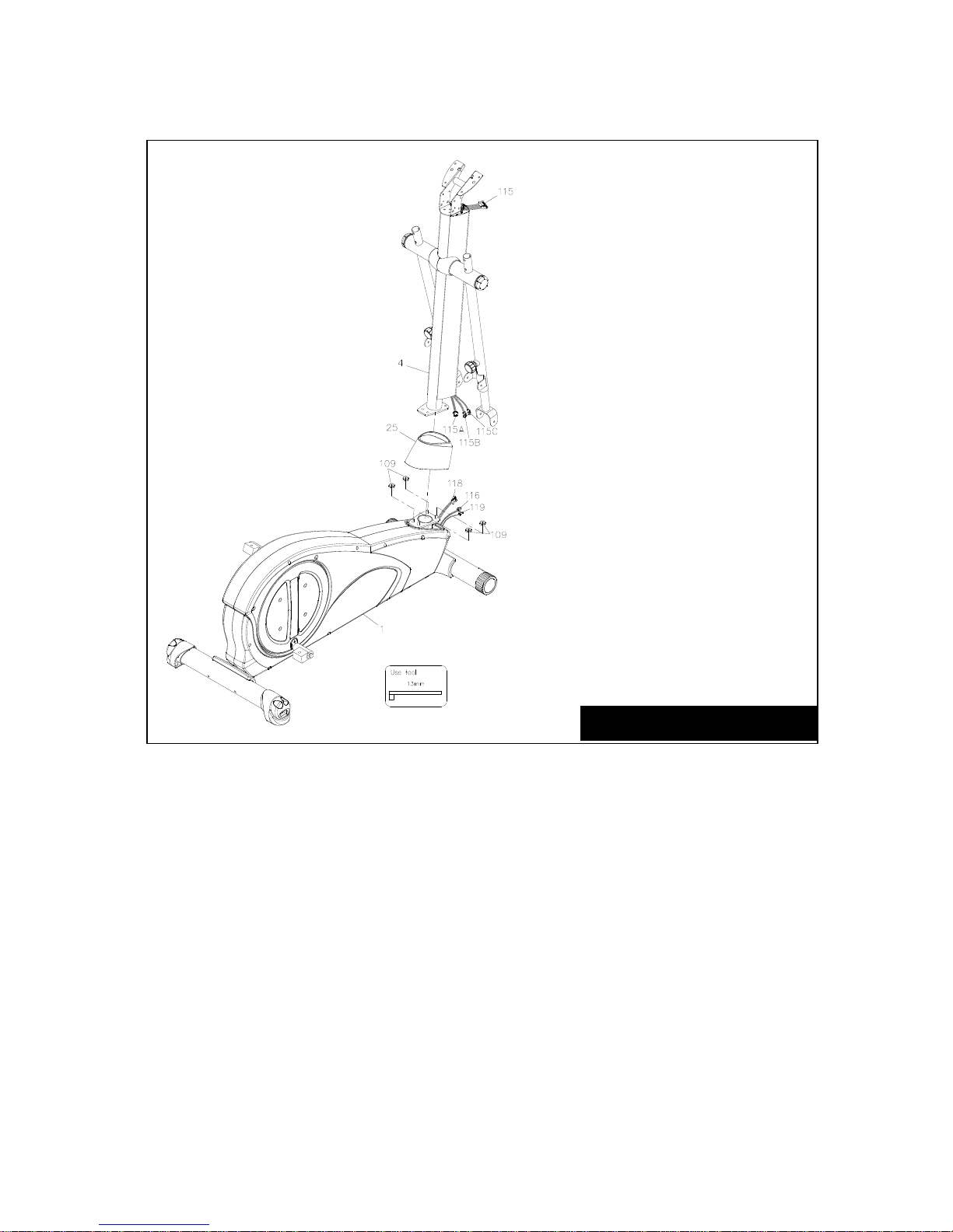
STEP 2 – Upright Post Assembly
a. Slide the Upright Sleeve (25) onto the Upright Post Assembly (4)
b. Remove the Nuts (109) from the Main Frame (1).
c. Attach the Upright Post Assembly (4) to the Main Frame (1), using 4 Nuts (109),
DO NOT tighten these nuts until STEP 4.
d. Connect the Cable (115A) at the bottom of the Upright to the Tension Control
Cable (118) inside the Main Frame Assembly.
e. Connect the Cable (115B) to the Power Extension Cable (116).
f. Connect the Cable (115C) to the Speed Sensor Cable (119).
g. Make sure the Cables are securely connected.
h. Make sure you DO NOT pinch the Cable.
i. Securely attached the Upright Sleeve (25) to the Main Frame Assembly (1)
USE HARDWARE KIT B
Page 15
15
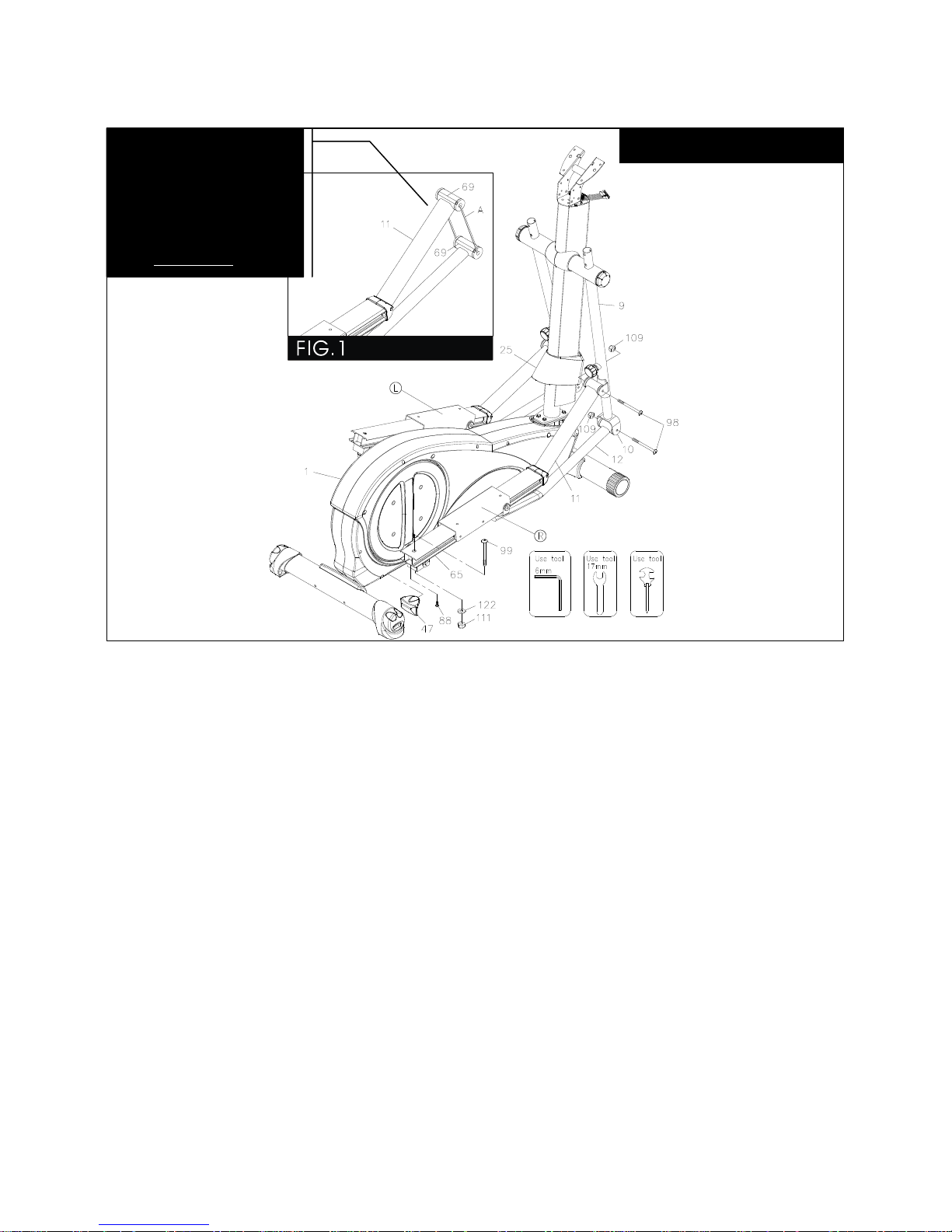
STEP 3 – Pedal Support Arm Assembly
a. DO NOT cut off the plastic ties that holds the Pedal Support Arm Assembly (12)
and the Lower Pedal Support Arm (12) together until STEP 3 – d.
b. Attach the rear end of the Right Pedal Support Arm (11) on the top of the Right
Rail Connector (54R), using 1 Bolt, Button Head (M10xp1.25x85mm) (99), 1
Washer (10x28x2.0t) (122) and one Nut (M10) (111). Hand tight.
c. Slide the Right Rail Cap (47) onto the rear end of the Right Pedal Support Arm
Assembly (11) using 1 Self-Tapping Screw, Flat Head (M4x16mm) (88). Secure
it with a Phillips Screw Driver.
d. Cut off the plastic ties that holds the Pedal Support Arm Assembly (12) and the
Lower Pedal Support Arm (12) using a wire cutter.
e. Attach the front end of the Right Pedal Support Arm Assembly (11) to the Right
Pivot Arm (9) using 1 Bolt, Button Head (M8xp1.25x90mm) (98) and 1 Nut (M8)
(109). Hand tight.
f. Attach the front end of the Lower Right Pedal Support Arm (12) to the Lower
Pivot Arm (10) using 1 Bolt, Button Head (M8xp1.25x90mm) (98) and 1 Nut
(M8) (109). hand tight.
g. Repeat the assembly steps above to the left side.
DO NOT tighten these Nuts and Bolts yet.
USE HARDWARE KIT B
Do not cut off the tie (A)
between the Pedal
Support Arm Assembly
(11) and the Lower
Pedal Support Arm (12)
until STEP 3 – d
Page 16
16
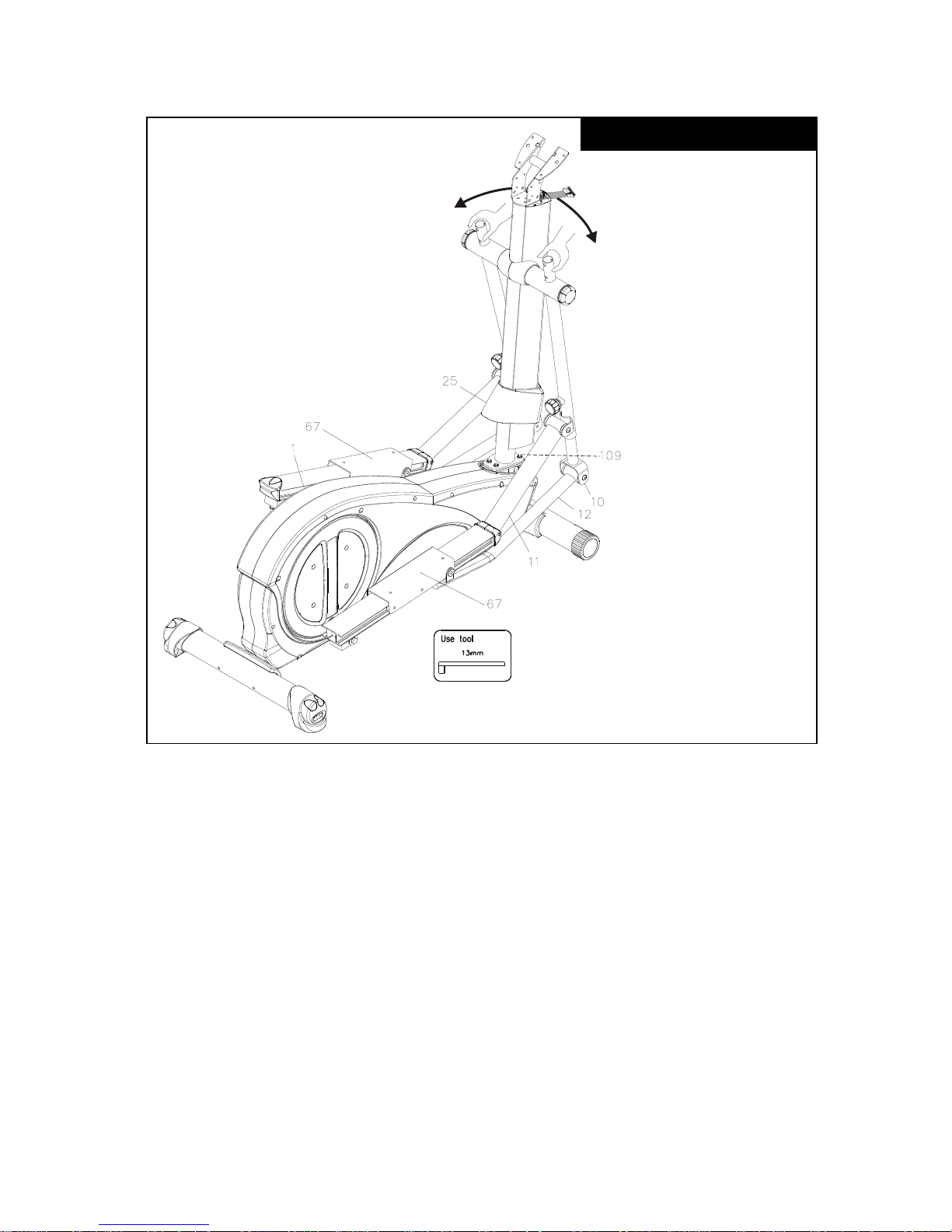
STEP 4 – Upright Post and Main Frame Assembly
a. Slide the Upright Sleeve (25) onto the Upright Post Assembly (4).
b. Attached the Upright Post Assembly (4) to the Main Frame (1), using 4 Nuts
(M8) (109) that attach to the Upright Post Assembly (4) and Main Frame (1).
c. Tighten all Nuts and Bolts with Wrenches.
d. Install the Upright Sleeve (25) to the Base Frame Shroud.
USE HARDWARE KIT B
Page 17
17
STEP 5 – Pivot Arm & Lower Pivot Arm Assembly
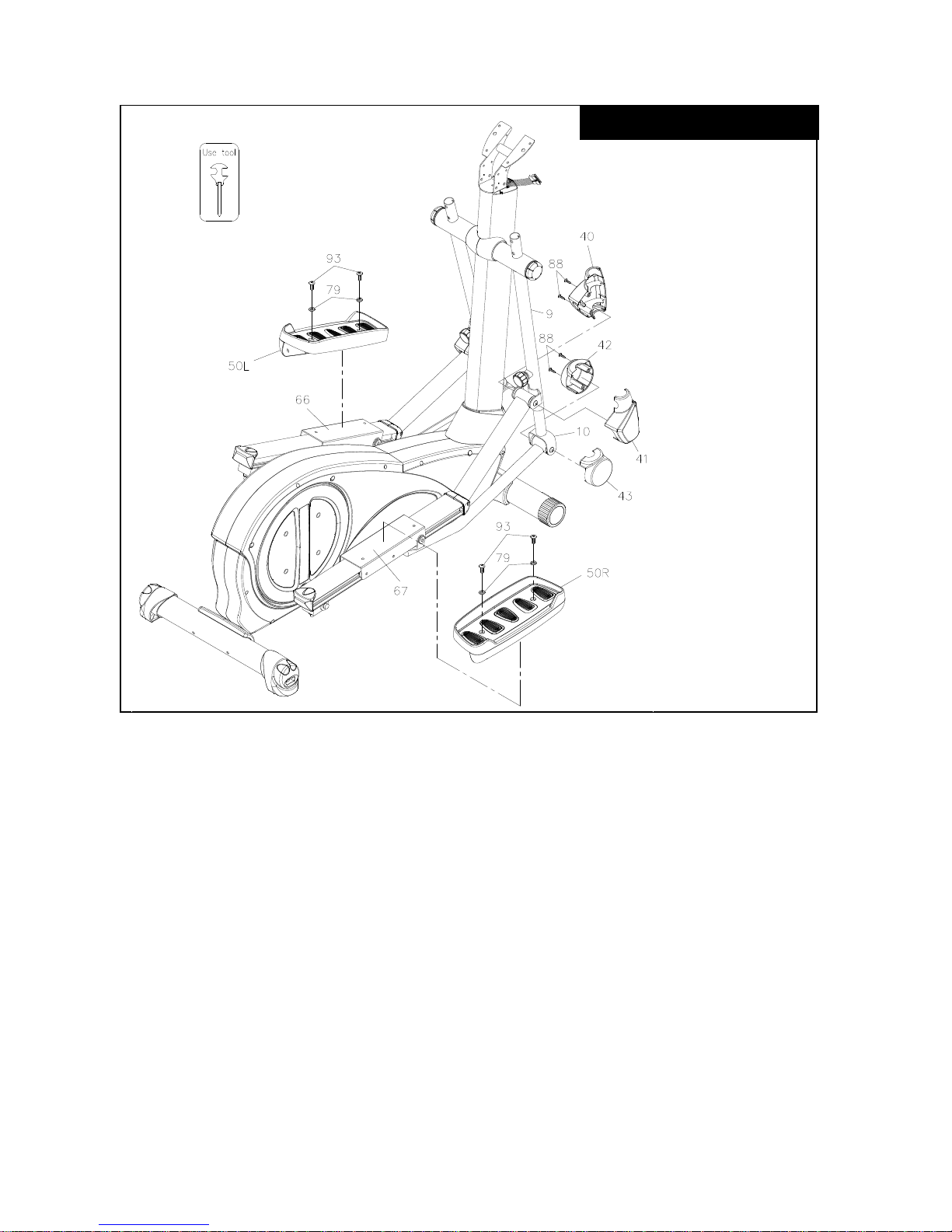
a. Install the Pivot Arm Cover (40 & 41) onto the Pivoting Arm (8 & 9), secure it
with 4 Self-Tapping Screws, Flat Head (M4x16mm) (88).
b. Install the Lower Pivot Arm Cover (42, 43) to the Lower Pivot Arm (10) and the
Pedal Support Arm (11 & 12), secure it with 4 Self-Tapping Screws, Flat Head
(M4x16mm) (88).
c. Tighten all 8 Screws with Phillips Screw Driver.
STEP 6 – Foot Pedal Assembly
a. Install the Foot Pad Assembly (50) on the Foot Pedal Slider (67), secure with 4
Lock Washers (M8) (79) and 4 Screws, Round Head (M8xp1.25x16mm) (93).
USE HARDWARE KIT B
Page 18
18
STEP 7 – Fixed Handlebar Assembly
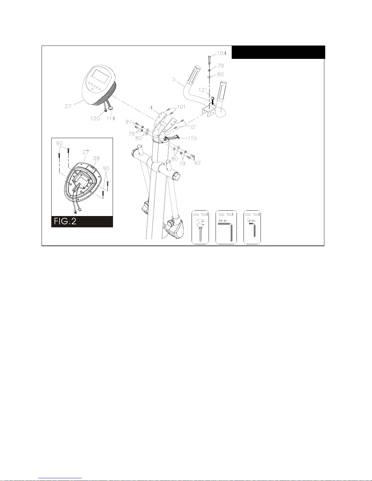
a. Remove the 4 Bolts, Button Head (M8xp1.25x16mm)(97) 4 Washers
(8x16x2.0t)(80), and 4 Lock Washers (M8)(79) from the Fixed Handlebar (5).
b. Install the Fixed Handlebar (5) to the metal bracket that welded on top of the
Upright Post Assembly (4), secure it with the Bolts and Washers removed in
STEP 7 – a.
c. Install a Socket Head Bolt (M8xp1.25x55mm)(104), 1 Lock Washer (M8)(79)
and 1 Washer (8x16x2.0t)(80) (found in Hardware Pack C) to the top of the
Fixed Handlebar metal bracket. Tighten all 5 Bolts securely with Wrench.
STEP 8 – Display Console Assembly
a. Attached the Display Console Bottom Sleeve (28) to the back of the Display
Console (27), secure it with 4 Screws, Pan Head (M5xp0.8x25mm)(90).
Tighten it with Phillips Screw Driver.
b. Install the Display Console Assembly to the metal plate that welded on top of the
Upright Post Assembly (4) using 4 Bolts, Socket Head (M6xp1.0x15mm)(101).
Tighten it securely with Wrench.
c. Connect the Display Console Cable (114) with the Extension Cable (115) and the
Pulse Sensor Cable (120) with the Pulse Sensor Extension Cable (121).
USE HARDWARE KIT C
Page 19
19
STEP 9 – Display Console Sleeve Cover Assembly
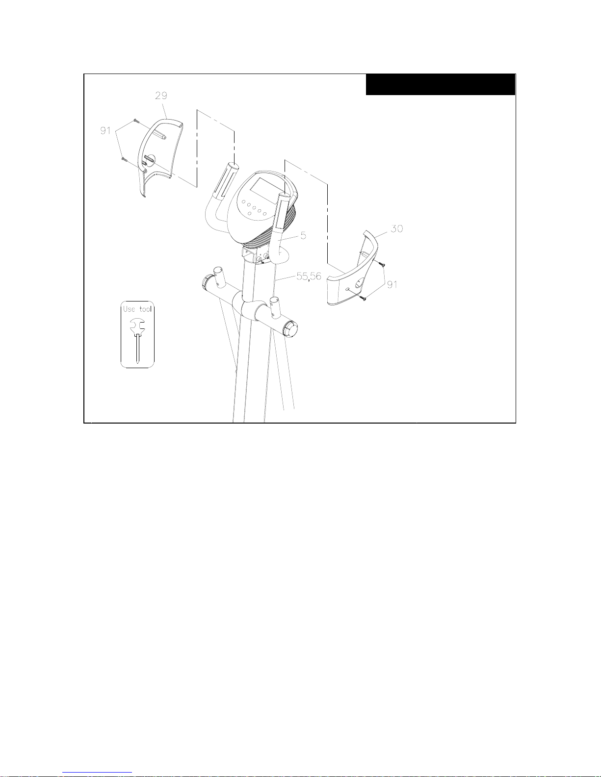
a. Slide the Right Console Sleeve Cover (30) thru the right & Left Handlebar (5).
b. Connect both Console Sleeve Covers (30 & 29) to the Upright Post Assembly (4).
Secure it with 4 Screws, Round Head
(M5xp0.8x15mm)(91).
c. Tighten it securely with a Phillips Screw Driver.
USE HARDWARE KIT C
Page 20
20
STEP 10 – Install the Handlebar
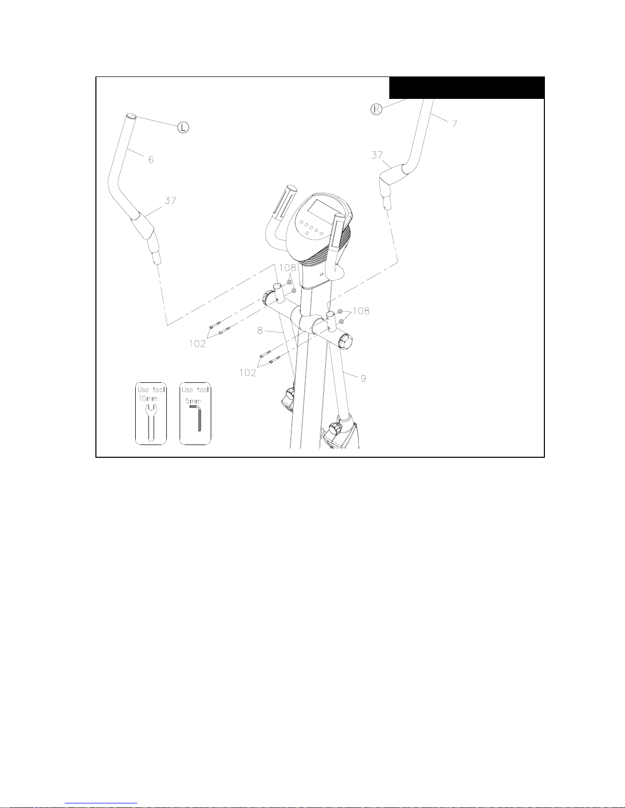
a. A “R” & a “L” marked at the end of each Handlebar (6 & 7).
b. Install the Right Handlebar (7) to the Pivot Arm (8 & 9) secure it with 4 Bolts,
Socket Head (M6xp1.0x35mm)(102) and 4 Nut (M6)(108). Tighten it securely
with Wrenches.
c. Slide down the Handlebar Sleeve (37) make sure it covers the Nuts and Bolts.
You have now completed the assembly. Please double check your work and
Tightening all Nuts and Bolts securely with tools.
USE HARDWARE KIT C
Page 21
21
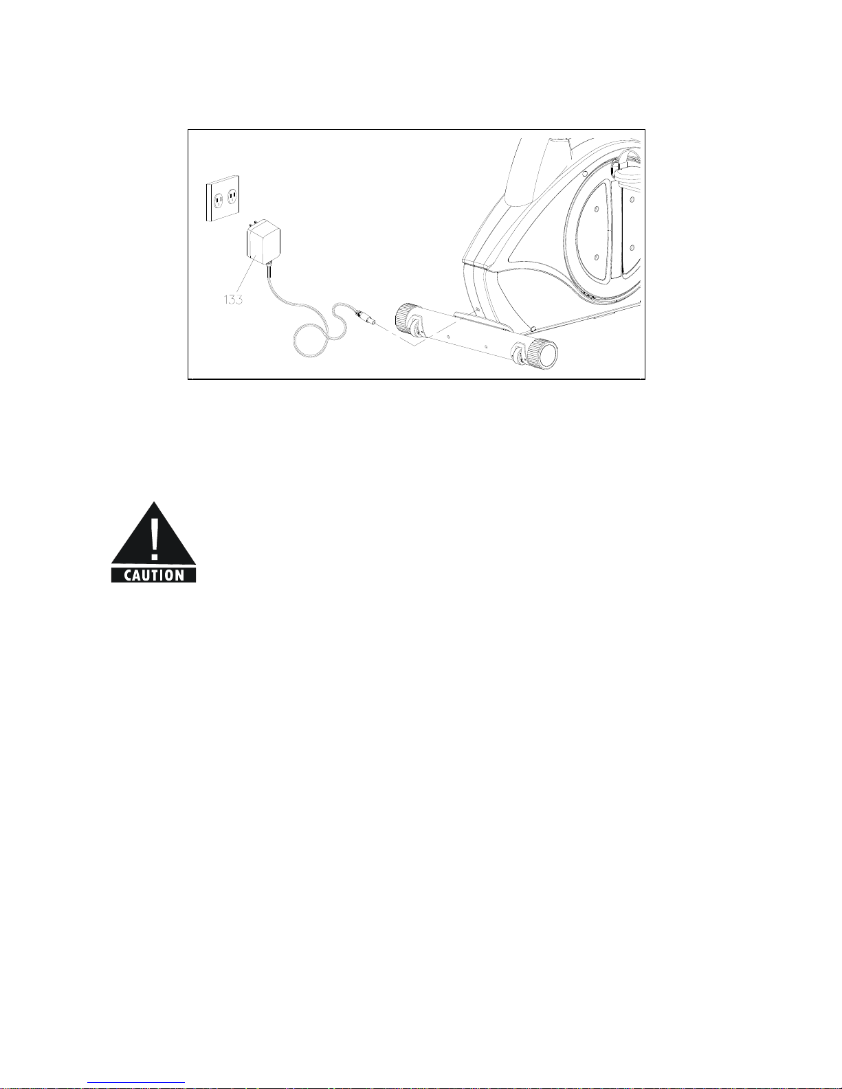
STEP 11 – AC Adaptor
Plug the AC Adaptor (117) into the socket in the FRONT of the Elliptical.
Your Elliptical Trainer is now ready to use. Please make sure that all Nuts and
Bolts are securely tightened before exercising.
Page 22
22
ADJUSTMENTS
Getting started
To reduce the risk of electrical shock, always unplug the unit before cleaning or
any maintainance activity.
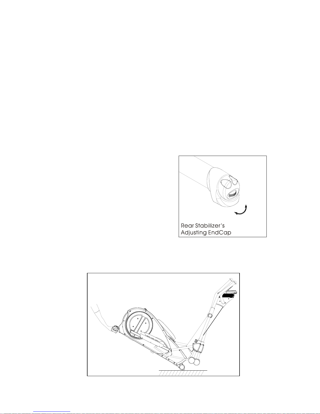
Uneven Floor
After placing the unit where it will be used, check its stability. If there is even a slight
rocking motion or the unit is not stable, determine which stabilizer is not resting on
the floor. To adjust the Built-In floor leveler in the Rear Stabilizer End Cap by turing
the wheel clockwise to lower or counter clockwise to raise.
Transport the Recumbent Cycle
There are Two Oversized Transport Wheel in the front of the Elliptical Trainer.
Page 23

23
Display Console angle can be adjusted by pulling it forward or back.
Page 24
24
HOW TO ADJUST THE STRIDE LENGTH
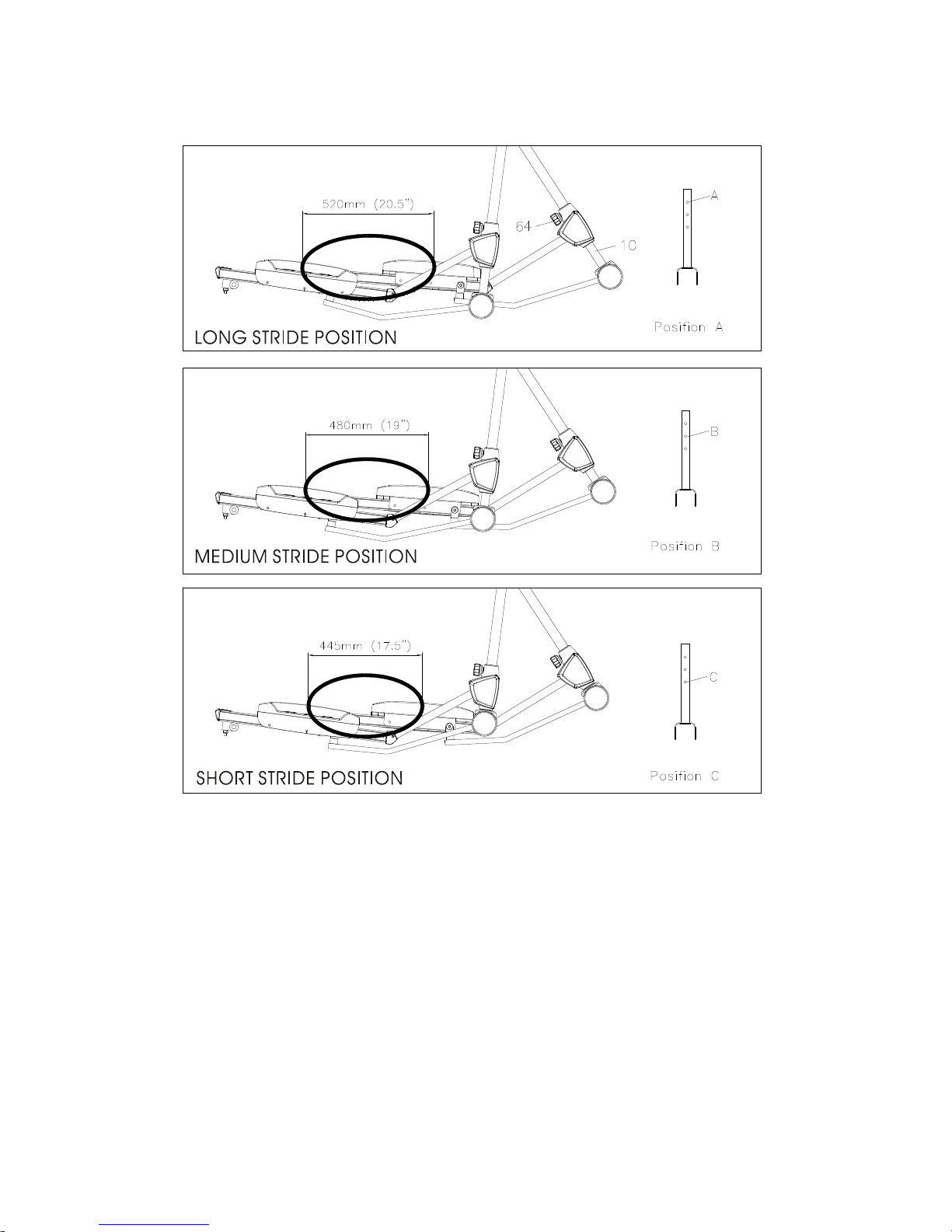
The stride of this Elliptical Trainer can be adjusted from 17.5’’ (445mm) to 20.5’’
(520mm).
How to increase the stride length.
a. loosen the Spring Loaded Lock Pin (64) by turning the Knob counterclockwise 3
turns, pull the knob outward, lowing the Lower Pedal Support Arm (10) toward
floor.
b. Release the Knob (64) and make sure the lock pin in the Lock Pin has engaged to
the hole in the Lower Pedal Support Arm (10). A click sound should be heard
when the Lock Pin has engaged to the Hole in the Support Arm.
c. Repeat the same process to adjust the stride length for the other foot pedal.
Page 25

25
Make sure both Foot Pedals are always adjusted at the same height.
Double check & tightening the Spring Loaded Lock Pin each time before using
the Elliptical Trainer.
Page 26

 Loading...