

Page 1
!
1!
MX300 NAV - COMM OWNER'S MANUAL
TKM, INC
14811 NORTH 73
rd
STREET
SCOTTSDALE, AZ 85260
PART # MN0300, REV. 4
NOV 10, 2008
Page 2

!
2!
I. INTRODUCTION
This manual contains information on the Michel MX300, manufactured by TKM, Inc. The
information includes installation, operation, mechanical and electrical descriptions, alignment
and test considerations. The MX300 is authorized by the Federal Aviation Administration to
TSO C34e, C36e, C37c, C38c, C40b and has met the test requirements ofRTCAlDO-160B.
A. Purpose of Equipment
The equipment is a 760 channel communication (COMM) transceiver for use in aviation services
and a 200 channel navigation (NAV) receiver to provide VOR I LOC signals
to navigational converters. The NA V receiver also provides frequency selection for remote
mounted Distance Measuring Equipment and Glide slope Receivers. Navigation converter
circuitry is included to interface ARC CDIs normally used with RT328T.
The MX300 is designed to be a direct replacement for the Cessna/ARC328T. The unit is
dimensionally identical to the ARC units and can therefore use existing aircraft installations.
Except for improved performance characteristics, the unit is electrically interchangeable with
the ARC unit and will provide the proper audio, navigation, and channeling signals for
existing installations. New installations can be made using RT328T installation kits.
Additionally, the MX300 will directly replace the following NAV/COMMs:
RT308C RT328A RT508A RT528A
RT328C RT528E
RT328D
The RT308C, RT328A, and RT528A use pin L instead of pin BB of J4 to output the NAV
demod signal. The MX300 may be modified in the field as described in Section VI.
While not manufactured by TKM, an adapter tray may be found commercially which permits
replacement of the following: RT514R, RT515R, RT515A-l, RT517, RT540.
B. Equipment Description
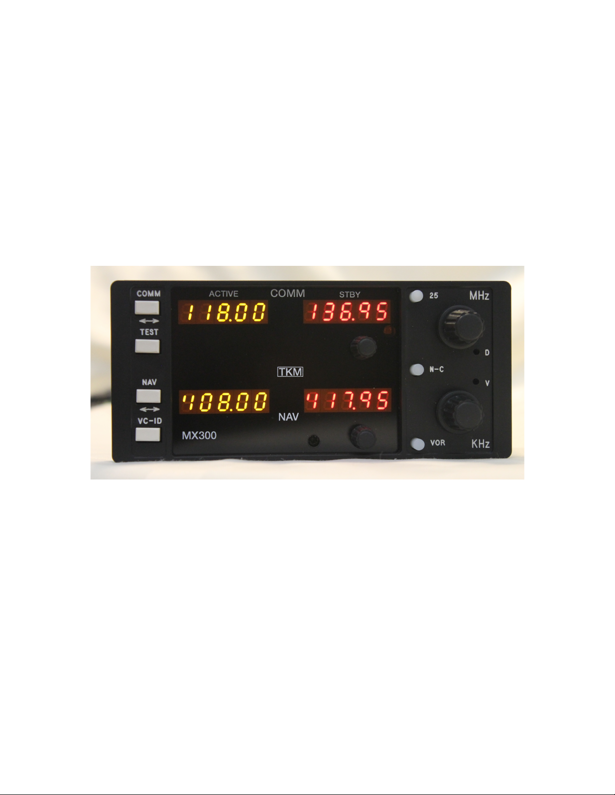
The unit features digital (LED) displays for active (yellow) frequency channel and
standby (red) frequency channel for both COMM and NAV.
For channel selection a MHz knob and a KHz knob are provided. For 25 KHz increments in
COMM, a 25 KHz button is provided. To activate COMM or NA V frequency selection, an
N/C button is provided. A tic appears in the selected standby channel display.
Channel selection operates on the standby channel only. When the desired channel is indicated
in the standby display, it may be placed into the active position by depressing the "Flip-flop"
button located between the displays. The active channel is then placed into the standby position.
!
The NAV receiver features a VC-ID button to permit selection of voice or ident reception.
In
the ident condition a tic is displayed on the active NAV channel display.
The COMM transceiver features a test button that overrides the squelch to verify proper
receiver operation and to allow reception of weak signals. Also provided on the active
COMM display is a tic to indicate transmitter power output.
Page 3

!
3!
The master power switch is integrated with the volume control.
The VOR test button, located on the front panel, allows injection of a 0 degree FROM
bearing into the navigation converter circuits. A bearing adjustment can then be made
through the adjustment hole (V) by the KHz switch.
The MX300 is comprised of eight replaceable subassemblies. Five of the subassemblies are
contained in shielded modules in order to reduce radio frequency interference. The five are
the NAV receiver, the NAV synthesizer, the COMM receiver, the COMM synthesizer, and
the Transmitter.
The remaining three subassemblies are the Rear Panel Assembly, the Front Panel Assembly
and the Computer Board. Integrated into the Rear Panel Assembly are the audio amplifier,
power converter, power line filter, remote channeling circuits, and the T/R switching. The
Front Panel assembly contains the digital displays and corresponding driver circuits, function
select switches, and volume controls. The Computer Board contains the microprocessor as
well as memory and program storage.
Also contained on the computer board are the audio processing and NAV converter
circuits.
The subassemblies are interconnected with plugs to facilitate module replacement. For
equipment repair it is typically recommended that complete subassemblies be replaced.
As an aid to locating a problematic subassembly, a set of analog test points is provided. The
analog test points include the receiver tuning voltages, the synthesizer control voltages and
the AGC lines.
!
!
!
!
!
!
!
!
!
!
!
!
!
!
!
!
!
!
Page 4

!
4!
C. Specifications
MX300 TRANSCEIVER
Mounting: Panel mounted, no shock mounting required
Size: 6.312 x 3.12 x 12.15 inches w/ connectors (16.03
x 7.92 x 30.86 cm)
Weight: 6.0 lbs excluding external connector and harness
Power Requirements: 13.75 Vdc (or 27.5v w/CONV) 1.8A
NA V and COMM Recv'r
Max COMM Total w/
Transmit (Tone) 7.1A (6.2A unmodulated).
COMM TRANSCEIVER
Crystal Controlled: 760 channel
Frequency Range: 118.00 to 136.975 MHz
Frequency Stability:
+1-
.003%. -20 to 50C
TRANSMITTER
VHF Power Output: 12
+1-4
watts minimum, 50 ohm
Modulation: 85% capability with 90% limiting provided
Microphone: Dynamic mike containing transistorized pre-amp
or carbon (must provide at least 120 mV rms into
500 ohm load)
Side tone: Adjustable up to 40 mw into 500 ohm
headphones
Duty Cycle: 1 minute on, 4 minutes off (20%)
COMM RECEIVER
Sensitivity: 1.5 uv (soft) will provide a 6 db minimum signal
plus noise ratio (KHz, 30% mod)
Selectivity: Typical 6 db at + 15 KHz, 40 db at +25 KHz,
+65 db at +50 KHz
Spurious Responses: Down at least 70 db
Squelch: Noise adaptive squelch with manual override
Page 5

!
5!
AGC Characteristics: From 2 to 100.000 uV audio output will not vary
more than 1 db.
NA V RECEIVER
Crystal Controlled: 200 Channels
Frequency Range: 108.00 to 117.95 MHz
Sensitivity: 1.5 uv (soft) will provide a half-flag indication
Selectivity: Typical 6 db at + 15 KHz, 60 db at +50 KHz
Spurious Responses: Down at least 70 db
Ident Filter: 15 db minimum
AGC Characteristics: From 2 to 100.000 uV audio output will not vary
more than 1 db
NAV Receiver Accuracy: Two sigma limit,
+1-
1 degree
NA V Output: With LOC adjusted for 0.35 Vrms, VOR = 0.5
Vrms (typical) into 20K ohms or greater load
impedance
DME Channeling: 2x5
GIS Channeling: 2x5
AUDIO
Auxiliary Audio Inputs: Five
(5) 500
ohms with 30 db isolation
between any two
Frequency Responses: Within 6 db from
350
Hz to
2500
Hz
Headphone Output:
50
mw into
500
ohm
Speaker Output:
4.5
Vrms into auxiliary input produces 5 watts
audio output
Page 6

!
6!
II. INSTALLATION
The MX300 is designed to be an exact replacement for the ARC RT328T and similar
units. As a replacement unit, the MX300 is inserted directly into the existing RT328T
mounting tray and the clamp screw tightened down with a #1
(.12S"
dia.) Phillips head
screw driver.
For new installations, installation instructions for the RT328T should be used.
To remove the MX300 from the mounting tray, it is important to note that the Channel
Selector Knobs should not be used. Applying excess pressure to the knobs can damage
the unit.
The first step in removing the MX300 from the mounting tray is to rotate the clamp screw
counterclockwise, using a #1
(.12S"
dia.) Phillips head screwdriver, until the mounting clamp
is fully disengaged. Please note that the clamp screw is a holding device and
not an extraction device. With the hold down clamp disengaged, one of the following
procedures should be used to complete removal:
A. If access gap between instrument panel and MX300 front panel is
.lS0"
or
greater, the King extraction tool
#071-604S-00
may be used.
B. If the tool is not available, a large flat bladed screwdriver may be used to gently
pry the unit loose. When the access gap is sufficient, grip the unit with both hands
and remove it gently from the tray, using care to apply pressure evenly.
**** NOTICE TO INSTALLER ****
The TKM MX170C NAV/COMM is authorized by the FAA to TSO C34e, C36e, C37d, C38d, and C40c. The
product is an incomplete system. In order to achieve a complete TSO quality system, the MX300
must
be
installed to configure in conjunction with a TSO C37/C38 authorized antenna and a TSO C34e authorized
navigation receiver.
It
is the responsibility of the installer to ensure proper installation.
****CONTINUED AIRWORTHINESS CHBA 98-18)****
Permission is hereby given to installers approved by the recognized aviation authority to reference excerpts
from the installation instructions provided by TKM Inc. in order to fulfill documentation requirements for
Instructions for Continued Airworthiness (lCA). Adequacy of the documents should not be assumed by this
permission. ICA documentation rests solely with the ICA applicant. The MX300 product is 'Repair on
Condition Only'.
III. OPERATING THE MX300
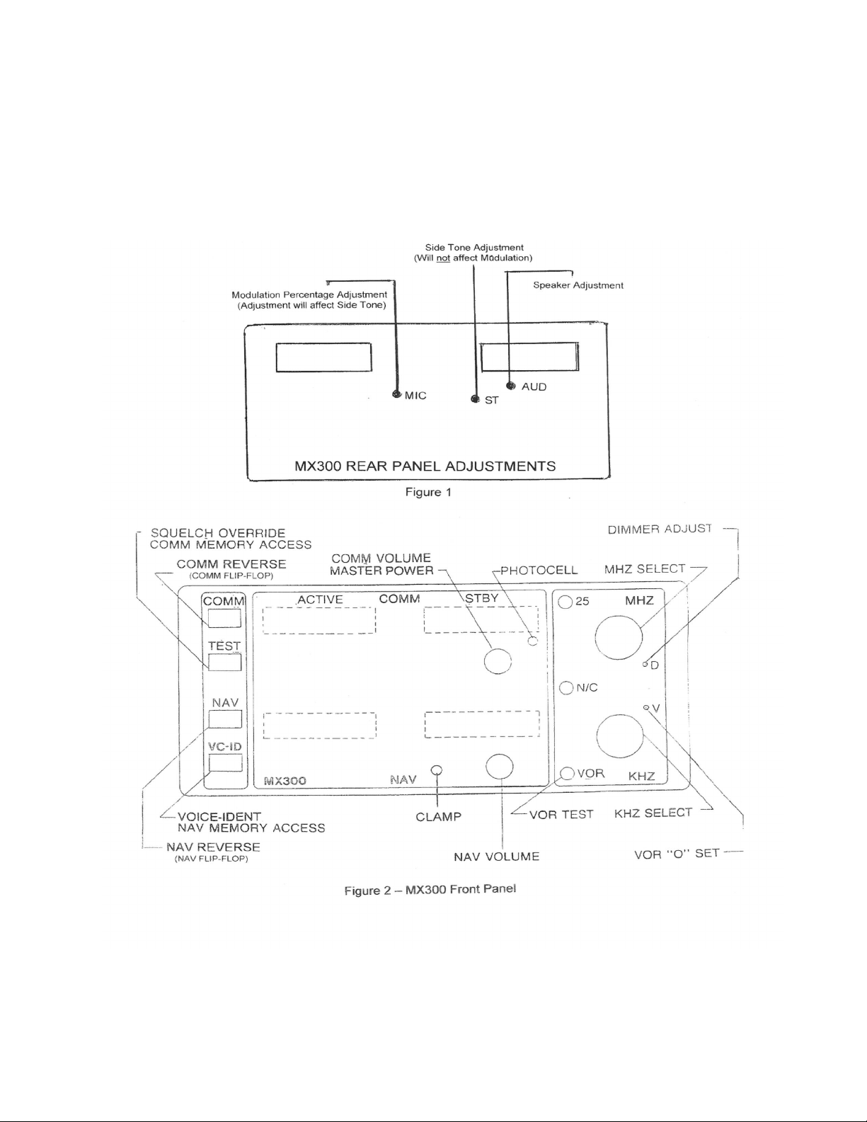
Operating controls for the MX300 are located on the front panel or through three access
holes in the rear panel. Through the rear panel, adjustments for modulation percentage, side
tone, and speakers can be made (see figure 1). Newer units will also have a squelch
adjustment accessible through a hole in the top cover.
The unit front panel is shown in figure 2. The left-hand COMM readout (yellow) indicates
the active COMM frequency and the right hand COMM readout (red) indicates the standby
COMM frequency. The left-hand NAV readout (yellow) indicates the active NAV frequency
and the right hand NAV readout (red) indicates the standby NAV frequency. A 'Tic' display
Page 7

!
7!
is provided in the upper left-hand corner of each of the four frequency readouts.
The active COMM 'Tic' indicates the presence of transmitter power.
The standby COMM 'Tic' indicates that the frequency selection knobs will control
COMM standby frequency.
The active NAV 'Tic' indicates that the NAV receiver is in the Ident Mode.
The standby NAV 'Tic' indicates that the frequency selector knobs will control NA V
standby frequency.
Power Application. The COMM volume control contains the master power switch and
activates both the NAV and COMM functions.
Frequency Selection. The N-C button is used to activate either the COMM (C) or the
NAV (N) frequency selection as indicated by the appropriate 'Tic' display. The MHz and
KHz controls can then be used to select a desired standby channel, or a stored channel
may be recalled from stored memory.
In
COMM, the '25' button is used to advance the
frequency by 25 KHz.
After the desired standby frequency is selected it may be transferred to the active position by
pressing the COMM Reverse or NA V Reverse buttons located left of the displays.
The COMM button flip-flops the COMM channels, and conversely, the NAV button flipflops
the NAV channels. The active and standby channels will be transposed each time these
buttons are pressed.
Ident/Voice Selection. The VC-ID button can be used to select a tone filter in order to receive
voice signals on the NA V receiver. The switch is also used for frequency storage as
described in Frequency Storage.
Test. The TEST button is a dual function switch.
In
normal operation, it is used to override
the squelch to verify receiver operation and to receive weak signals. The switch is also used
for frequency storage as described in Frequency Storage.
Frequency Storage. Up to 100 frequencies, 50 NAV and 50 COMM may be stored in the
MX300 memory. The following procedure will allow storage of new frequencies:
1) Set standby display to 10000. This is done by pressing and holding the TEST button (for
COMM) or the VC-ID button (for NAV), then repeatedly press the appropriate flipflop
button until 10000 appears in the standby display. Release the buttons.
Note: 10000 is permanently stored in memory. If no other frequencies are in memory, the
standby display will show 10000.
2) Dial in the frequency to be stored. Hold the TEST (COMM) or VC-ID (NAV) and
press the appropriate flip-flop button to store the new frequency. The new frequency, now
in memory storage, will disappear and the next available stored frequency will appear in
Page 8

!
8!
the standby display.
3) Additional channels may be added by repeating steps 1 and 2.
Channel Recall. To recall channels in memory, hold the TEST or VC-ID button while
repeatedly pressing the appropriate flip-flop button. The channels will sequence in the
order they were stored.
Clearing Memory. To delete a single channel, do the following:
1) Recall channel in the standby display as described above.
2) Using the channel selector switches, bring up 10000 in the standby display.
3) Hold the TEST or VC-ID button and the corresponding flip-flop. The desired channel will be
deleted.
*
To clear the entire memory, both NAV and COMM, except for factory presets:
1) Turn radio off.
2) While holding down the TEST button, turn the radio on. The unit will reset to factory preset
default channels in both active and standby (COMM
121.50/120.00)
(NAV 108.001112.00).
Transmit. The transmit mode on the transceiver is selected by grounding the MIC Key line
on the unit's rear panel.
VOR OBS Adjustment. OBS test may be initiated by depressing the VOR button and
centering the CDI needle with the OBS knob. The L-R needle should be centered with a
bearing of 0 degrees FROM or 180 degrees TO. If an error exists, the VOR bearing may be
adjusted through the 'V' hole in the front panel.
IV. EOUIPMENT LIMITATIONS
The following limitations indicate where the MX300 may be installed and meet the
applicable TSO requirements.
l. Equipment is intended for installation within a non-pressurized but controlled
temperature location in an aircraft that is operated at altitudes up to 35000 feet MSL.
2. Equipment is intended for use in a Standard Humidity Environment.
3. Equipment is intended to be panel mounted in Single and Multi Engine Fixed Wing
Aircraft with Reciprocating and Turboprop Engines.
4. Equipment shall not be mounted less than 0.3 m from magnetic compass.
5. Unit has not been tested with autopilots
Page 9

!
9!
V. ENVIRONMENTAL OUALIFICATION FORM
Model MX300 NAV I COMM as specified in MX300 Specifications manufactured by
TKM, Inc., 14811 NORTH 73
rd
STREET, SCOTTSDALE, AZ 85260.
CONDITIONS D0160B para DESCRIPTION OF TEST
Temperature and Alt. 4.0 Category Cl
Low Temperature 4.5.1 Category Cl
High Temperature 4.5.2 Category Cl
Altitude 4.6.1 Category Cl
Decompression 4.6.2 Not Tested
Overpressure 4.6.3 Not Tested
Temperature Variation 5.0 Category C
Humidity 6.0 Category A
Shock 7.0 Tested for all Conditions
Vibration 8.0 Category S (no shock mts)
Explosion 9.0 X: Not Tested
Waterproofness 10.0 X: Not Tested
Fluid Susceptibility 11.0 X: Not Tested
Sand and Dust 12.0 X: Not Tested
Fungus 13.0 X: Not Tested
Salt Spray 14.0 X: Not Tested
Magnetic Effect 15.0 Category A
Power Input 16.0 Category B
Voltage Spike Condo 17.0 Category B
Audio Spike Suscept. 18.0 Category B
Induced Sig. Suscept. 19.0 Category B
RF Susceptibility 20.0 Category B
RF Emission 21.0 Category B
Page 10
!
10!
Installation Instructions: The MX300 is designed to be a slide in replacement for ARC
radios and, as such, shall be installed with all of the original equipment precautions.
VI. ILLUSTRATIONS
!
!
!
!
!
!
!
!
!
!
!
!
!
!
!
!
!
!
!
!
!
!
!
!
!
!
!
!
!
!
!
!
Page 11
!
11!
!
!
!
!
!
!
Page 12
!
12!
!
!
!
!
!
!
!
!
!
!
!
!
!
!
!
!
!
!
!
!
!
!
!
!
!
!
!
!
!
!
!
!
!
!
!
!
!
!
!
!
!
!
 Loading...