

TKM MX170C Owner's Manual
!
1!
MX170C NAV-COMM OWNER'S MANUAL
TKM, INC
14811 NORTH 73
rd
STREET
SCOTTSDALE, AZ 85260
PART# MN0170C, REV. 1
NOV 17,2008

!
2!
I. INTRODUCTION
This manual contains information on the TKM MX170(C), manufactured by TKM, Inc.
The information includes installation, operation, mechanical and electrical descriptions
and alignment and test considerations. The MX170(C) is authorized by the Federal
Aviation Administration to TSO C34e, C36e, C37d, C38d, C40c, and has met the test
requirements of RTCAlDO-160C.
A. Purpose of Equipment
The equipment is a 760 channel communication (COMM) transceiver for use in aviation
services and a 200 channel navigation (NAV) receiver to provide VOR / LOC signals to
navigational converters. The NAV receiver also provides frequency selection for remote
mounted Distance Measuring Equipment and Glide slope Receivers.
The MX170(C) is designed to be a direct replacement for the King KX170/ KX175.
The unit is dimensionally identical to the King units and can therefore use existing
aircraft installations. Except for improved performance characteristics, the unit is
electrically interchangeable with the King units and will provide the proper audio,
navigation and channeling signals for existing installations. New installations can
be made using KX170A installation kits.
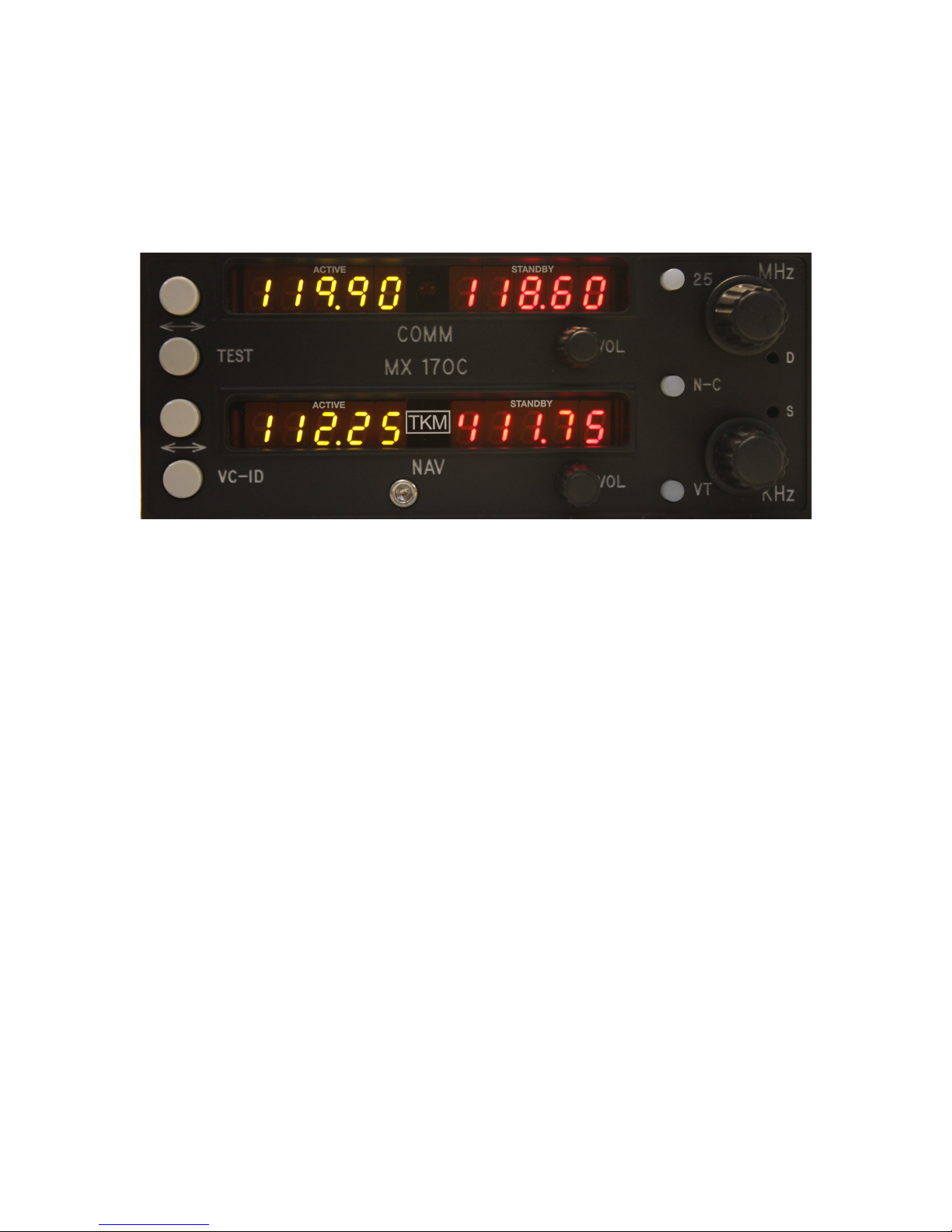
B. Equipment Description
The unit features digital (LED) displays for active (yellow) frequency channel
and standby (red) frequency channel for both COMM and NAV.
For channel selection a MHz knob and a KHz knob are provided. For 25 KHz
increments in COMM, a 25 KHz button is provided. To activate COMM or NAV
frequency selection, an N -C button is provided, a tic appears in the selected
standby channel display.
Channel selection operates on the standby channel only. When the desired channel is
indicated in the standby display, it may be placed into the active position by depressing
the 'Flip-flop' button located left of the displays. The active channel is then placed into
the standby position.
The NAV receiver features a VC-ID button to permit selection of voice or ident
reception.
In
the Ident condition a 'tic' is displayed on the active NAV channel display.
The COMM transceiver features a test button that overrides the squelch to verify
proper receiver operation and to allow reception of weak signals. Also provided on the
active COMM display is a 'tic' to indicate transmitter power output.
!
Power switches are incorporated with the NAV and COMM volume controls. The
COMM is the master power switch and the NAV provides power switching for remote
navigation units.

!
3!
The MX170(C) is comprised of eight replaceable subassemblies. Five of the
subassemblies are contained in shielded modules in order to reduce radio frequency
interference. The five are the NA V receiver, the NA V synthesizer, the COMM
receiver, the COMM synthesizer, and the Transmitter.
The remaining three subassemblies are the Rear Panel Assembly, the Front Panel
Assembly and the Computer Board. The Rear Panel Assembly contains the Audio
Amplifier, Power Filter, and the
T/R
switching. The Front Panel Assembly contains the
digital displays, the function select switches and the volume controls. The Computer
Board contains the microprocessor, the memory, and program storage.
Also contained on the computer board are the audio processing circuits and
the channeling circuits.
The subassemblies are interconnected with plugs so that any module may be
replaced without the use of a soldering iron. For equipment repair it is recommended
that complete subassemblies be replaced.
As an aid to locating the defective subassembly a set of analog test points are provided.
The analog test points include the receiver tuning voltages, synthesizer control voltages,
and the AGC lines.
C. Specifications
MXI70(C) TRANSCEIVER
Mounting: Panel mounted, no shock mounting required.
Size: 6.312 x 2.600 x 14.15 inches
w/
connectors
(16.03 x 6.60 x 35.94 cm)
Weight: 4.9 lbs. excluding external connector and harness.
Power Requirements: 13.75 Vdc (or v
w/CONV)
NAV and COMM Recv'r 1.7A
Max COMM Total
wi
Transmit (Tone) 7.1A (6.2A unmodulated)
COMM Transceiver
Crystal Controlled: 760 channel
Frequency Range: 118.00 to 136.975 MHz
Frequency Stability: + .003%. -20 to 50C

!
4!
Transmitter
VHF Power Output: 8 watts minimum, 50 ohm
Modulation: 85% capability with 90% limiting provided.
Microphone: Dynamic mike containing transistorized pre-amp
or carbon (must provide at least 120 m Vrms into
500 ohm load).
Side tone: Adjustable up to 40 mw into 500 ohm
headphones.
Duty Cycle: 1 minute on, 4 minutes off (20%)
Receiver
Sensitivity: 1.5 uv (soft) will provide a 6 db minimum signal
plus noise to noise ratio (KHz, 30% mod).
Selectivity: Typical 6 db at
+1-7.5
KHz, 60 db at
+1-
17.5 KHz, 90 db at +25KHz
Spurious Responses: Down at least 70 db.
Squelch: Noise adaptive squelch with override.
AGC Characteristics: From 2 to 100.000 uV audio
output will not vary more than 1 db.
NAV Receiver
Crystal Controlled: 200 Channels
Frequency Range: 108.00 to 117.95 MHz
Sensitivity: 1.5 uv (soft) will provide a half flag indication.
Selectivity: Typical 6 db at
+1-
15 KHz 60 db at
+1-
35 KHz, 80db at + 50 KHz
Spurious Responses: Down at least 70 db.

!
5!
Ident Filter: 15 db minimum
AGC Characteristics: From 26 to 100.000 uV audio output will not
vary more than 1 db.
NAV Receiver Accuracy: Two sigma limit,
+1-
1 degree
NA V Output: With LOC adjusted for 0.35 Vrms VOR = 0.5
Vrms (Typical) into 20K ohms or greater load
impedance.
DME Channeling
M0
M1
M2#
M3
##
K0
K1#
K2
K3#
##
50#
KHz#
##################
108
-
- 0 -
.0X 0 0
-
-
.XO
-
109
-
- - 0
.1X 0 0 0 -
.X5
0
110
0
- -#-
.2X 0 0 0 0
##
##
111
0
- -#-
.3X
- 0 0
0
##
##
112
0
0 0#-
.4X
-
-
0
0
##113
- 0 0 0 .5X 0 -
-
0#####
114
0
- 0 0
.6X
- 0 -
-
##
##
115
- 0 -
-
.7X
-
- 0 -
##
##
116
0
- 0 -
.8X
-
-
-
0
##
##
117
0 0 -
0
.9X 0 -
-
-
##
##
NOTE: (-) = OPEN, (0) = GROUND
ILS Energize: OPEN for VOR, GROUND for ILS
 Loading...