

TKM K4S Installation & Running Manual

1
FORMULA TKM 4-STROKE
Installation & Running Guide
Introduction
Thank you for buying the TKM K4S 4-stroke engine which offers to karting the combination of high
performance and low weight to bring great racing at a budget cost.
TKM K4S engines are designed and manufactured exclusively for use within kart racing environments on fit
for purpose kart tracks with sealed type smooth surfaces. Any other type of usage is outside the engine’s
use of parameters.
TKM K4S engines should only be installed and operated by those with suitable knowledge and experience,
and we take no responsibility for warranty or other claims where incorrect installation or operation has been
carried out.
As with any high performance engine it is vital that you look after the engine to ensure it is running correctly.
Look after the engine well, run it correctly and you’ll have many hours of trouble-free driving.
Please be very careful to study this guide before you install & run the engine to ensure it is being operated
correctly. Also make sure that you keep within the service periods recommended within the guide. We wish
you great racing & fun.
The TKM K4S engine package is provided to you in a form which is easy to fit to your kart and should take
less than an hour with minimal needs.
Warning: Identifies an instruction, which if not followed may cause injury or endanger the life of the driver,
mechanic or third party or may cause damage to your TKM K4S engine.
General precaution and safety information for engine installation & running
Warning: For the best possible engine operation, compliance with the following advice regarding
installation of engine and equipment is required.
Warning: Modifications to engine or equipment are not allowed.
Warning: Besides the engine-specific installation advice, also take note of information from the respective
chassis manufacturer where available.
Step 1
Engine comes complete with:- Radiator (Standard engine mounted or larger Enduro brake side of chassis
mounted), Carburettor, Noise box, Exhaust, Engine Mount (less clamps), and the Oil Breather Condenser
Pot together with the Petrol Pulse Pump mounted on the seat bracket with pipes.
The standard engine mounts are available in either: 90 x 32mm or 92 x 32mm. They are stamped with 90 or
92 on the bottom face in a recess for identification. Other sizes of mounts are available to special order.
Step 2
Place the engine onto the chassis and ensure that the engine mounts fit correctly. Make sure that the engine
is clear of seat brackets and can slide along the chassis rails a small distance to allow for chain adjustment.
We can supply you with a set of 2 rising blocks with 4 longer bolts to raise engine by 9mm to give extra
2
clearance on side bar mounting if required. Fit your existing mount clamps providing there are suitable and
secure lightly with mount clamp bolts. Ensure that the mount clamp bolts are the correct length and neither
too long so that they bottom or too short so that there is insufficient thread holding.
Step 3
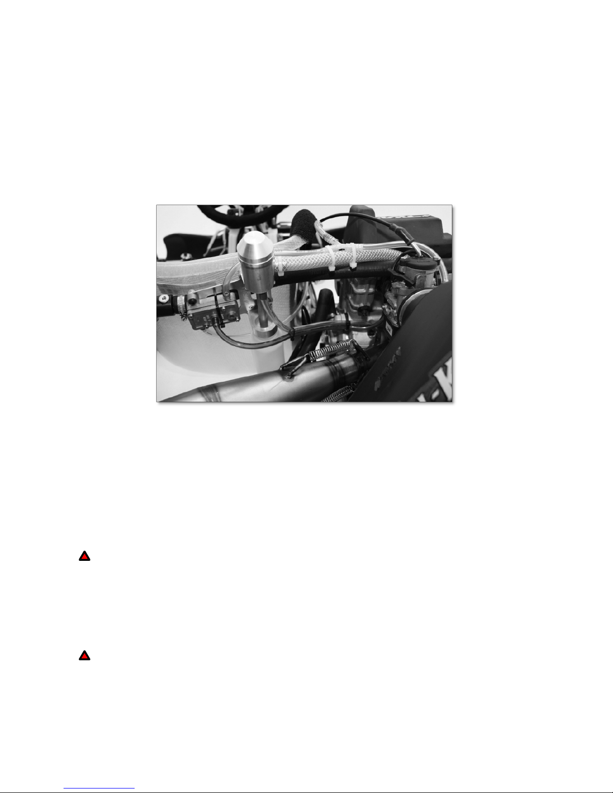
Take the bracket with condenser pot and pulse pump mounted and locate on the rear of the seat. This
should be mounted as high as possible on the seat so that the top of the condenser unit is at least 30mm
above the seat lip. The pot must also be as close as possible to vertical. It should be fitted to the rear of the
seat but to the right hand side of the centre point so that it is close to the engine. Drill the seat and mount
using the bolts and spacers provided.
When bolting up note that there is 10 degrees of rotational adjustment available in the M5 slotted holes of
the condenser pot mount on the bracket. This makes it easy to gain the best position for the main large
breather pipe from the engine. See picture below.
Condenser pot mounting to seat
Step 4
Connecting the oil breather pipes. The small clear oil return pipe should be connected from the engine to
the small union at the bottom of the pot ensuring that there is a nice smooth steady fall on the pipe from
condenser to engine. Trim if required and cable tie. Without this steady fall oil will collect in pipe and restrict
oil returning to engine.
The larger bore plastic pipe should run straight up from the engine and then naturally over the top of the carb
inlet manifold and across to the condenser pot union with a steady rise if possible. Again trim if required.
Secure with a cable tie – though note this is the pipe you will have to remove to insert oil into the engine.
Warning: Do not run the engine without oil as this will lead to engine failure.
Step 5
Connect the fuel system piping. But first remember that if you have previously been using the fuel tank
with a two-stroke engine you MUST empty the tank and flush with clean unmixed fuel in a safe environment.
Also note that this engine requires an extra outlet/inlet on the tank (three in total) so this should be fitted in
the top of the tank at this stage. Make sure the tank is clean and flushed after drilling and fitting of extra
union. An inline tank filter is highly recommended.
Warning: When handling fuel, do not smoke or allow naked flames. Gasoline and gasoline vapour are
highly flammable and explosive under certain conditions.
Pipe 1(Fuel Supply) is connected from the tank pick-up connector to the in arrow union on the pulse pump.
Pipe 2 (Fuel Supply) goes from the pulse pump out arrow union to one end of the Y connector (not fitted with
the 70 fuel return jet).

3
Pipe 3 (Fuel Supply) goes from the long end of the Y connector to the carburettor in union.
Pipe 4 (Fuel Return) goes from the remaining short end of the Y connector (with 70 jet) to the new fuel tank
union. This is the fuel return pipe.
Pipe 5 (Breather Pipe) goes from the tank to act as a breather – ideally located into a high mounted catch
tank. The Y connector should be located as high as possible on the kart just between the engine and the
condenser pot bracket. The Y connector arm with return jet inserted should be highest of all. This helps to
remove trapped air from the pipes. All of the pipes when trimmed to length and connected must be cable tie
neatly in position without deforming or reducing their internal bores which could cause fuel starvation.
Warning: Ensure that all fuel pipes cannot chafe or rub against other parts which could cause a fuel leak.
Note that the blue pulse pipe from the engine brass pulse union located under the inlet manifold goes to the
rearward facing brass pulse union on the pulse pump.
Step 6
Check the alignment of the axle sprocket with the clutch sprocket teeth, adjusting as necessary ensuring
that you have sufficient axle key located in the sprocket carrier. Remember that you will need less teeth on
the rear sprocket than with a two-stroke. Try 12T: 68T as a good starting point. If the sprocket carrier does
not have sufficient location on the key then it can always be turned around so its offset can cover the key.
Once complete, fit chain and adjust (12mm of total up & down movement) ready for use, remembering to
fully tighten the clamp bolts. Finally adjust fitment of the fully enclosed plastic chain guard to ensure it does
not rub against the exhaust and it is spaced out from axle bearing to suit the chain alignment.
Step 7
Fit the exhaust onto the manifold with both securing springs and also locate with springs onto exhaust cradle
mount.
Warning: The position of this exhaust cradle MUST be adjusted to ensure a natural fit with no tension on
the exhaust manifold. If this is not done then the exhaust manifold pipe may touch plastic float
bowl on carb during running which will cause dangerous fuel leaks.
Please note a special Exhaust Manifold and Cranked Exhaust is available for Pro-Karts with brake discs
located in the centre of the axle.
Step 8
Fit noise box to carb inlet with the twin air inlet filters facing approximately downwards. Note you will need a
bracket to secure the noise box from its mounting bush to a suitable location such as a securing bolt on the
rear axle bearing. Tal-Ko offer a bracket set for its own karts, though every make of kart will require
something different. It is vital to use such a support bracket and the noise box must always be supported
firmly in a natural position with no pull on carb as this will cause the carb rubber inlet connector to engine to
fracture.
Step 9
The carburettor throttle cable will need fitting to the slide of the carb. Simply remove the carb top (2 Bolts)
remove slide assembly and push cable through cable swan neck, large spring and outer small hole in needle
retaining plate. Place end of cable into the slide cable slot and reassemble carb top. Then thread through
outer cable and connect to the pedal. It is important to ensure that the pedal locates against a bolt at full
throttle to prevent damage to the carb or pull on the rubber inlet connecting manifold.
Warning: The carburettor throttle cable must not be kinked or restricted as the carburettor slide might
stick in full throttle open position.
Step 10
Next connect the ignition on/off switch. This can be fitted anywhere suitable, though we provide with the
engine a bracket that allows you to fit switch on the M8 bolt holding the upper plastic steering column bush to
chassis just above the tank. It may well require a new longer length bolt when this bracket is fitted to allow
the bolt to fully enter the Nyloc part of its securing nut.
Connect a red wire from the switch to the spare red short lead coming off the coil unit. Another lead must be
earthed from the switch to the engine coil earth lead bolt. If this earth is not good then the switch will not

4
operate. Ensure both wires are neatly secured with cable ties or PVC tape. Remember to clearly mark the
On/Off positions.
Step 11
A radiator coolant catch tank must be used. It can be fitted in between bottom of radiator and engine near
clutch guard using a cable tie on bottom radiator bracket on standard engine mounted radiator or on the
bracket designated for it with the larger brake side mounted Enduro Radiator.
Warning: Please follow the instruction of the chassis manufacturer for mounting the water coolant hoses
to the chassis if available.
Warning: For Enduro radiator installation to the chassis please follow the instruction of the chassis
manufacturer if available.
Enduro Radiator (Optional)
In very hot weather or warm climate countries we advise use of the optional Enduro style radiator system.
This comprises of a larger radiator fitted to the brake side of kart. Tal-Ko supplies the full kit which includes
radiator, pipes and mounting brackets. The use of an inline thermostat is also advised with this radiator. This
thermostat is not included in the kit and can also be purchased from Tal-Ko.
Warning: The engine temperature should not exceed 90C as exceeding the engine temperature could
lead to serious engine failure.
Picture shows an Enduro type radiator fitted to kart.
Step 12
You will need to drill/cut holes in both the outside and inside faces of the sidepod to allow access for the
remote hand held starter shaft.
Please note that if you wish to install a temperature gauge then the sensor MUST be located in the special
location hole provided at the top of the engine. This will have an M10 x 1 taper plug in place which should be
removed and the sensor fitted with PTFE tape to prevent leakage.
 Loading...