

Page 1
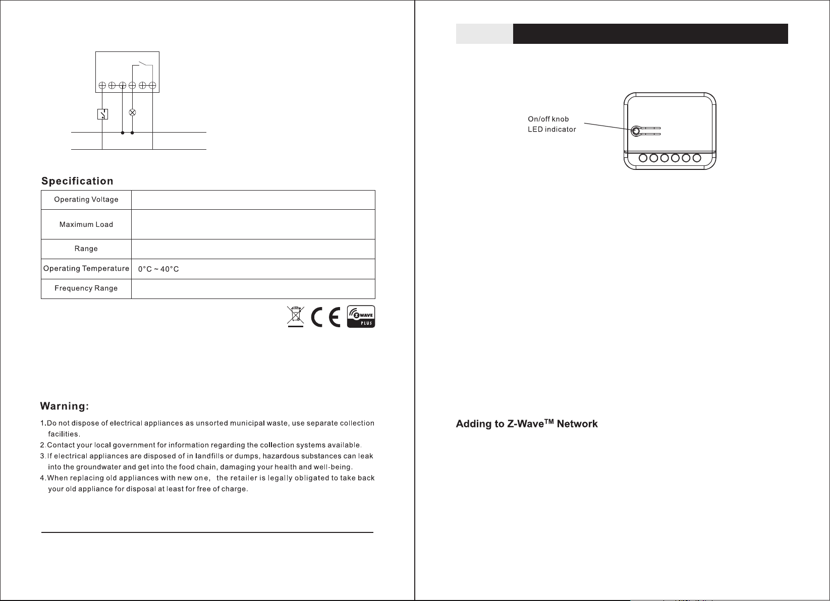
Wiring diagram
NN
S
TZ79
Relay
LL
NO1
Insert switch module
L: Lin e volta ge i nput
NO1: S witch ed l oad out put
N: Lin e neutr al
S: Con ne ct to wall sw it ch inpu t
N
SWITCH
Load
L
AC110V~230V 5 0H z/ 60Hz
3000W,(1500W for US)
Mini mu m 40 m in door 70m o ut do or line of si gh t
868. 4M Hz (EU),90 8. 4M HZ(US), 92 1. 4MHz(AU ), 869MHz( RU )
Interop era bil ity with Z-WAVE devices
A Z-Wa ve n etwork can in te gr ate devic es o f va rious cla ss es m ad e by different ma nu fa cturers.
The TZ78 can b e in co rp orated in to e xi sting Z- Wa ve networ ks . Th e TZ7 8 m od u le ca n b e us ed
to car ry o ut i nc lusion, as so ciation , or e xc lusion.
1
N
S
N
L
L
NO
Note : Th is mod u le mus t b e“I ncl u ded in th e ne two rk”, an d suitabl e fo r whe re it wi ll be
pe r m a nent l y in s t alle d . Th e pro p e r op e r atio n of t h is n o d e i n the m esh net w ork is
depe nd ent on it k now ing it ’s loc ati o n w ith re spe ct to other nodes. You can not " tes t
benc h" c onfigur e th is modu le , then inst al l.
Th i s i n sert swi tch modu l e i n a tra nscei ver whic h i s a Z-Wa v e enabled dev ice
and is fully compatible with any Z-Wave enabled network. Z-Wave enabled devices
displaying the Z-Wave logo can also be used with it regardless of the manufacturer,
an d ou rs c an also be used in oth er m anuf a ctur er's Z-Wave en abled ne two rks.
Remote On/Off control of the connected load is possible with other manufacturer's
wi rele s s c ontro ller. Each sw i tch is d e s i gned t o a c t as a repeater. Rep e ater s
will re-t ran smit the RF si gnal to ensu re that the signal is received by it s intended
destina tio n by routing t he signal ar oun d obstacle s and r adio dead sp ots .
This plug-in On/Off switch is able to detect current wattage (5~3000W) and overload
wattage(3010~3300W) of connected lights or appliances. When detecting overload
state, the Switch will be disabled and its On/Off button will be lockout of which LED
will flash quickly. However, unplug and re-connect the switch will reset its ove rload
conditi on to n ormal stat us.
The product supports Over The Air(OTA) feature for the products firmware upgrade.
-4-
TZ79-V2.0 - 20 16 .3.6
In the fron t casing, th ere i s an On/Off button wi th LE D indicato r which is use d to
to g gle swi t ch o n a nd o ff or carr y o u t i n clus ion, ex clu sion, rese t or as sociatio n.
When first power is appl ied, its LED flashes on and off alt ernately a nd re peatedly
at 1-second intervals. It implies that it has not been assi gne d a node ID and ca n not
work with Z -Wave ena ble d devices.
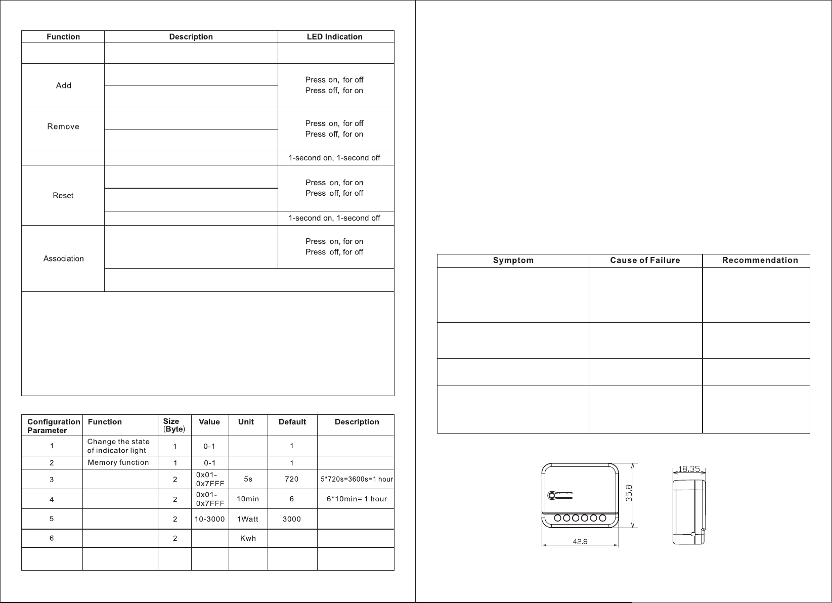
The table b elo w lists an ope ration s umma r y o f b a sic Z-Wave fun ction s. Pl ease
re f er to t he inst r ucti o ns for your Z-Wa v e ce r t i f i c a t e d prim a r y co n t r o l ler t o
TM
access th e set up functio n, and to incl ude /exclude /as sociate de vic es.
-1-
Page 2
No node ID
The Z-Wave Controller does not allocate
a node ID to the Switch.
1-second on, 1-second off
1. Have Z-Wave Controller entered inclusion
mode.
2. Pressing On/Off button three times within
1.5 seconds will enter inclusion mode.
1. Have Z-Wave Controller entered exclusion
mode.
2. Pressing On/Off button three times within
1.5 seconds will enter exclusion mode.
Node ID has been excluded.
1. Pressing On/Off button three times within
1.5 seconds will enter inclusion mode.
2. Within 5 second, press On/Off button again
for 1 seconds until LED is off.
3. ID is excluded
1. Have Z-Wave Controller entered association
mode.
Or Pressing On/Off button three times within
1.5 seconds will enter association mode
2. There are two groups for the switch
Each group can associate max five devices.
※ Including a node ID allocated by Z-Wave controller means Add. Excluding a node ID allocated by
Z-Wave controller means remove.
※ Failed or success in including/excluding the node ID can be viewed from the Z-Wave controller.
※ Association:it can be associated by Z-Wave devices with association
※ Use the"Reset" procedure only in the event that the network primary controller is missing or
otherwise inoperable
※ The group identifier is "Group 1 ".
Association group info report command class
Profile:General lifeline (Profile MSB=0x00,Profile LSB=0x01)
Association group name report command class
Group 1 :lifeline
Z-Wave Configuration
watt Meter Repo rt Period:
If the setti ng is configured for 1 hour (set value =72 0), the TZ79 will report its instant power consumption every 1 ho ur
to Z- Wa ve Con tr o ll er. The ma xim um in te rv al to r ep or t it s instant po wer consumpti on is 45 hours (5s*32767/3600
=45hr).
KWH Meter Repor t Period:
If the setti ng is configured for 1hour (set value =6), the TZ79 will report its Accumulated Power Consumption (KW/h)
every 1 hour to Z-Wave controller. The maximum interval to report its Accumulated Power Consumption (KW/h) is 227.55
days (10min*3276 7/1440=227.55 days).
Threshold of Watt for Load Caution:
In the above form, w he n the v al ue is 3 00 0, if r el ay 1 lo ad by belo w 3000 wa tt t urn ed int o more than 3000 wat t,
wil l imm ediately send the instantaneous load w value to Gr oup 1. The max imum set scope is 3000 watt, mi nim um
sca le value of 10 watt, the default value is 3000 watt.
Threshold of KWH for Load Caution :
In the above form, when the value of 10000, when the accumulation of relay1 consumed power more than 10000 KWH,
will immediately send the accumula tion of current consumed power to group1 . Maximum can set range t0 10000 KWH,
minimum scale value is 1 KWH, the default value is 0, 0 not have load caution.
Memory funct ion:
Stated in the above form, TZ7 9 by default valu e is 1, when the valu e is 0, TZ79 memory fu nction not open ; When
the value is 1, open TZ79 memory function.
Change the state of indicatorlight :
Stated in the above form, the defaul t val ue is 1, when the val ue of TZ79 i s 0, socket LED indicator will be on when
the light statu s is " on "; When set to 1 , the socket LED indicator will be off when the light status is " on ".
The sw itch is n’ t worki ng
and LE D off
The sw ich LED i ll umina ting, b ut c an
not co ntrol t he O n/Off swi tch of the
load a ttach ed
The sw itch LE D il lumin ating ,b ut the
cont roler c an n ot cont rol the s wi tch
LED ke ep flas hi ng, but c annot
cont rol
1.Th e switc h is n ot
conn ected t o th e power
2. The swi tch is out of
orde r
Chec k if the lo ad p lugge d
into t he swit ch h as its ow n
On/O ff s witch
1. Not c arry ou t as socia tion
2. Fre quenc y in terfe rence
Over load oc cu rs
1. Che ck powe r
conn ectio ns
2. Don 't open u p th e
swit ch and se nd i t
to rep air.
Set th e On/Off
swit ch of the l oa d
atta ched to o n
1. Car ry out as so ciati on
2. Wa it for a wh il e to re-t ry
Remo ve the lo ad a ttach ed
or che ck max.
load c annot e xc eed
3010 W 3300 W~
Product size (mm)
Wat t Me ter
Repo rt p er iod
KWH Me te r
Repo rt p er iod
Thre sh ol d of Wat t
for lo ad c au tion
Thre sh ol d of KWH
for lo ad c au tion
7
Edge or Pulse mode
or Edge-Toggle mode
0-10 00 0
1 1-3 3
-2-
0
1:Edge mo de
2:Pulse m od e
3:Edge- to gl e mo de
-3-
 Loading...