


S-Blender
Mini Mastering Console
The S-Blender is a mini mastering console with two stereo inserts for parallel / serial
processing and it’s a perfect tool for mixing and mastering. The five-step mode control
changes the signal path and numerous combinations can be tested without reconnecting any
outboard.
The first insert has a semi-fixed position and the second insert can be positioned at four
different points in the signal path. At the push of a button the two inserts swap position
and by using the mute buttons previewing can be done without altering the level controls.
For easy integration The S-blender has a separate monitor section with a volume control and
a mono switch. It’s the optimal unit for two-stage compression combining parallel and serial
compression in a clean and simple way.
Mastering-grade circuits and a switch matrix with gold-plated relays guarantee maximum
performance.
Key Features
* Unique parallel and serial processing * Mastering grade performance
* Gold plated relays * Monitor section with volume control
With two outboard processors connected – for example two compressors, or a compressor
and an EQ – numerous combinations can be achieved at the twist of a knob. Interfaced with a
DAW and a monitoring system the S-blender can be used for both processing and monitor
control.
Function
Ch1 / Ch2 blend control
ins1
B
D
Ch3 level control
main level
+
C
monitor level
main output
monitor output
input
Ch1
A
S
Ch2
Ch3
A,B,C,D are insert points for insert2
The input signal is split into three separate channels:
Channel 1 is the unprocessed sound. Channel 2 has the Insert 1 inserted. Channel 3 is only
active in Mode 5, and otherwise muted. Insert 2 moves around in the signal path depending
on the mode setting. It’s also possible to swap the position of the two inserts by pressing the
swap button.
The three channels are followed by a mix point with a blend control between channel 1 and 2.
When Mode 5 is enabled Channel 3 can be mixed into the signal with a separate volume
control. The channel mute buttons cuts the signal without affecting the other channels making it
possible to preview channels without altering any level controls.
Insert 1 is always inserted into channel 2 for parallel processing. Insert 2 can be placed at
four different points in the signal-path.
Modes
Mode 1 - Insert 1 active on channel 2 for parallel processing.
Mode 2 - Insert 2 is placed before the split point.
Mode 3 - Insert 2 is placed in series with insert 1.
Mode 4 - Insert 2 is placed after the mix point.
Mode 5 - Insert 2 is sent to channel 3 for parallel processing.
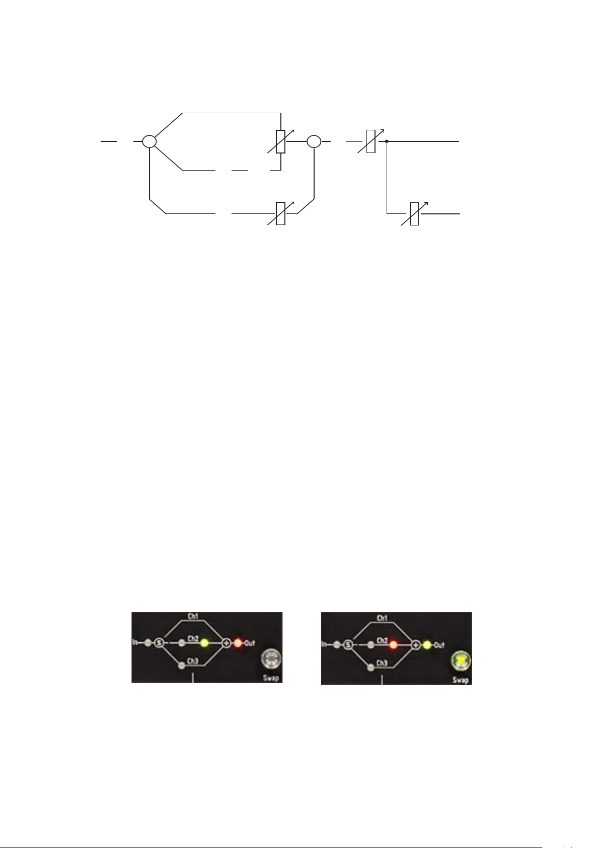
A green LED shows the position of Insert 1 and a red LED shows position of Insert 2.
Swap
The swap switch change places of the two inserts.
Left picture shows insert 1 inserted into Ch2 and insert 2 inserted after the mix point as a
main output insert. Right picture shows the position of the two inserts after pushing the swap
switch. A sep arate page shows all 10 different modes.

Main level
The main level is placed right before the main output.
Monitor section
The monitor signal is fed directly from the output connectors through its own dedicated level
control. A mono switch is also provided for checking mono compatibility . The mono switch
does not affect the main signal.
Chassi ground
A chassi to audio ground jumper is located on the main circuit board right behind the Ch2
mute switch.
115V / 230V main power
A voltage selector is placed inside the unit to the right of the blue main transformer.
The main fuse is located in the AC-inlet. Use 100mA for 230V and 200mA for 115V.
Inputs and outputs
All male connectors are outputs and all female connectors are inputs. All in- and outputs are
electronically balanced.
Input impedance 24 Kohm. Output impedance 50 ohm.
EU - Declaration of conformity
Product
TK Audio S-Blender / Mini Mastering Console
115v - 200mA, 230v - 100mA
Manufactor
Thomas Kristiansson
Musikverkstan / TK Audio
Falkenbergsgatan 10
30233 Halmstad
Sweden
Halmstad, April 2013
Declaration of conformity
I declare under my sole responsibilty that this product, to which this declaration relates, is
in confomity with the following standards:
EN55013, EN55020:2002, EN61000-3-2, EN61000-4-2 and EN60065
Following the provision of 73/23/EEC, 89/336/EEC and 93/68/EEC.

Modes
Insert1 = Green Insert2 = Red Grey = muted, Ch3 only active in mode 5
In
1
2
s
In
s
Ch1
Ch2
Ch3
Ch1
Ch2
Ch3
Ch1
+
+
Out
Out
In
In
S = splitpoint, + = mixpoint
Swap selected
Ch1
s
s
Ch2
Ch3
Ch1
Ch2
Ch3
Ch1
+
+
Out
Out
In
3
4
5
s
In
s
In
s
Ch2
Ch3
Ch1
Ch2
Ch3
Ch1
Ch2
Ch3
+
+
+
Out
Out
Out
In
s
In
s
In
s
Ch2
Ch3
Ch1
Ch2
Ch3
Ch1
Ch2
Ch3
+
+
+
Out
Out
Out
 Loading...