

Page 1
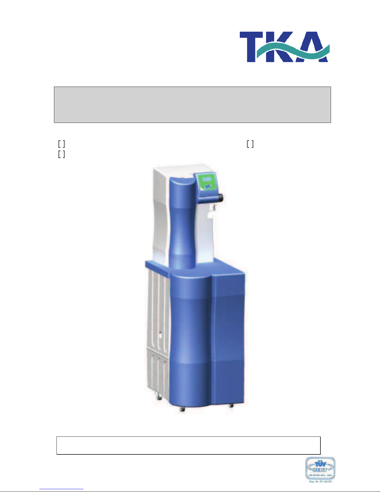
Operating Instructions
LabTower EDI
!
" Art. no.: 07.4415 ! " Art. no.: 07.4445
!
" Art. no.: 07.4430
Serial no.: ..........................
Read these Operating Instructions prior to starting to install and operate the
system!
29.0233, Stand: 06.09 Rights to technical changes reserved!
Page 2

LabTower EDI
Ultrapure water system
2
Company
TKA Wasseraufbereitungssysteme GmbH
Stockland 3
D-56412 Niederelbert
EC Declaration of Conformity
acc. to EC Directive 98/37/EC
- Machines Directive -
We herewith declare that the design and construction of the machine named below, and the
versions of it that we have introduced into the market, conform to the fundamental safety and
health requirements of EC Directive 98/37/EC.
This declaration becomes invalid when changes which were not agreed to by us are made to
the machine.
Description of the machine: Ultrapure water system
Machine type: LabTower EDI
Article number: 07.4415
07.4430
07.4445
Applicable EC Directives: EC Machines Directive (98/37/EC)
EC Low Voltage Directive (73/23/EEC)
EC Electromagnetic Compatibility Directive
(2004/108/EC)
Standards applied: DIN EN ISO 12100-1
DIN EN ISO 12100-2
DIN EN 60204-1
DIN EN 55011
DIN EN 50082-2
Niederelbert, 18. June 2007 ________________________________
Authorized Manufacturer’s Representative
Page 3

LabTower EDI
Ultrapure water system
3
Preface
Dear Sir or Madam,
in deciding to purchase a Ultrapure water system of type LabTower EDI you have selected a
high-quality product.
Thank you for the confidence you have placed in us.
Before you start to install and operate your Ultrapure water system, please carefully read the
information on how it is to be properly installed and operated that is given in these Operating
Instructions.
This is particularly important, as we, the manufacturer, cannot accept liability for any damage
occurring as a result of improper operation of this system, or from use of it for other than the
intended purpose.
Niederelbert, 18 June 2007
Page 4

LabTower EDI
Ultrapure water system
4
1. Contents
Preface......................................................................................................... 3
1. Contents.................................................................................................. 4
2. Notes on the Operating Instructions ....................................................... 6
3. Transport and packaging ........................................................................ 7
3.1 Examination on receipt......................................................................................... 7
3.2 Compaints ............................................................................................................ 7
3.3 Packaging and return shipment............................................................................ 7
4. Safety instructions................................................................................... 8
5. Extent of delivery .................................................................................... 9
6. Technical specifications ........................................................................10
7. Flow chart ............................................................................................. 12
7.1 How the system functions .................................................................................. 15
8. The installation area.............................................................................. 17
9. Putting into operation ............................................................................18
10. Operating elements............................................................................. 20
11. System control .................................................................................... 21
11.1 User menu........................................................................................................ 21
11.1.1 Permeate conductivity: ............................................................................................21
11.1.2 Product water conductivity: ......................................................................................22
11.1.3 Ultrapure water limiting value: .................................................................................22
11.1.4 Operating hours: ......................................................................................................23
12.1.5 Pretreatment operating hours: .................................................................................23
11.1.6 Cleaning:..................................................................................................................23
11.1.7 Disinfection: .............................................................................................................24
11.1.8 Fault storage:...........................................................................................................24
11.1.9 Unlocking the system:..............................................................................................25
11.2 OEM menu ....................................................................................................... 29
11.2.1 Maximum temperature: ............................................................................................ 29
11.2.2 Disinfectionszeit:......................................................................................................30
11.2.3 Recirculation time: ...................................................................................................30
11.2.4 Rinsing time: ............................................................................................................30
11.2.5 Interval rinse time: ...................................................................................................31
Page 5

LabTower EDI
Ultrapure water system
5
11.2.6 Real-time clock:....................................................................................................... 31
11.2 7 Sending interval: ..................................................................................................... 31
11.2.8 Language: ............................................................................................................... 32
11.2.9 Switching units: ....................................................................................................... 32
11.2.10 Switch off of temperature compensation: .............................................................. 32
11.2.11 Adjusting the circuit hysteris of the float switch: .................................................... 33
11.2.12 Programme choice UPW/ PW/ EDI: ...................................................................... 33
11.2.13 Entering the type and serial number of the system: .............................................. 33
11.3 Printer output ....................................................................................................34
11.3.1 Standard message: ................................................................................................. 34
11.3.2 Code message: ....................................................................................................... 34
11.3.3 Fault message:........................................................................................................ 34
12. Maintenance....................................................................................... 35
12.1 Rinsing the membrane ..................................................................... 36
12.2 Replacing the pre-treatment ............................................................. 37
12.3 Replacing the RO-membrane........................................................... 38
12.4 Changing the Ultrapure water module.............................................. 39
12.5 Disinfection procedure...................................................................... 40
13. Trouble shooting................................................................................. 43
14. List of replacement parts .................................................................... 46
15. Accessories ........................................................................................ 48
16. Consumable materials:....................................................................... 48
17. Terminal assignment .......................................................................... 49
18. Maintenance record............................................................................ 51
Page 6
LabTower EDI
Ultrapure water system
6
2. Notes on the Operating Instructions
Danger notes are emphasized by a warning triangle.
Important notes are marked with an information sign.
The information provided in these Operating Instructions is only valid for the system whose
serial number is written in on the front page.
Please write the serial number of your LabTower system on
the front page.
* You can find the serial number on the type plate of your Ultrapure water system.
For all inquiries and replacement parts orders, it is important that you correctly state the
following:
- Serial no.
- Article no.
Page 7
LabTower EDI
Ultrapure water system
7
3. Transport and packaging
TKA Ultrapure water systems are carefully checked and packed prior to shipment, but there is
nevertheless always a possibility that damage to them could occur during shipment.
3.1 Examination on receipt
! Check the completeness of the delivery against the shipping papers.
Is the packaging damaged?
! Check the system for damage.
3.2 Compaints
Should the system have been damaged during transport:
! Immediately contact the post office, railway or forwarding agent*.
! Keep the packaging, including the outer cardboard box, for a possible inspection
and/or return shipment.
3.3 Packaging and return shipment
Whenever possible, use the original packaging and packaging materials.
Should this no longer be available:
! Pack the system in packing film and in a strong cardboard box so that it is held
shock-proof.
* Complaints are only valid for 6 days (after receipt of the goods).
After this time, the right to claim for damages expires.
Page 8

LabTower EDI
Ultrapure water system
8
4. Safety instructions
! Your LabTower EDI system is a modularly constructed Ultrapure water system that
serves exclusively for the purification of tap water.
! Do not start to install and operate the system until you have read through the correspond-
ding information that is given in these Operating Instructions.
! Note that the manufacturer is freed from all liability for damages that result from improper
operation of the system, or from use of it for other than the intended purpose.
! The CE-Mark is invalidated should constructional changes be made to the system or
products of other manufacturers be installed in it.
! Protect the system from frost. The temperature in the area in which the system is installed
must be at least +2°C and must not exceed + 35°C.
! Observe all applicable and appropriate regulations and requirements, including current
accident regulations, and the statics of the flooring in the area of installation of the system.
! The feedwater pressure must be at least 2 bar and at most 6 bar. If the feedwater
pressure is higher, install an additional pressure reducer.
! DIN EN 1717 requires that water purification systems be equipped with a safety device
that protects the drinking water system from contamination.
! A 230V/50Hz electric safety socket with earth contact must be planned.
! The installation area must have a drain at floor level with at least DN 50 pipe. The
manufacturer will otherwise not accept any liability for water damage. Should no such
drain be available, then we recommend that a water watcher (art.-no. 16.0129) must be
installed.
! Gravity fall to the waste drain must be ensured.
! After long standstill periods (e.g. annual holidays) the system must be rinsed and, if
appropriate, disinfected. Refer to the “Cleaning and disinfection“ section for details.
! When selecting the installation area and installing the system, make sure that there is
sufficient working area for convenient operation of it.
! Never look directly at a switched-on UV-lamp, as ultraviolet light can impair eyesight! The
UV-lamp is only to be changed by TKA or by TKA authorized personnel.
! The guarantee is valid for a period of 12 months.
! For your own safety, please observe the safety precautions given above !
Page 9
LabTower EDI
Ultrapure water system
9
5. Extent of delivery
The LabTower EDI Ultrapure water system consists of:
1 x LabTower EDI Article no. 07.44__
1 x Assembly kit Article no. 25.0086
consisting of:
1 x Ultrapure water module Article no. 09.2005
1 x Prefilter cartridge 5µm + activated carbon, 5“ Article no. 06.5203
1 x Hardness stabilization, 5“ Article no. 06.5453
1 x Connector Article no. 14.0402
1 x Fine filter 1 µm, 10" Article no. 06.5101
1 x Connecting kit Article no. 25.0085
1 x Operating Instructions Article no. 29.0233
Connecting kit Article no. 25.0085
consisting of:
3 x Connecting hoses, PE, Ø8/Ø6 x 3m Article no.: 18.0036
2 x POM Insert Article no.: 14.0189
2 x Gasket 3/4" Article no.: 21.5008
2 x Union nut, R 3/4" Article no.: 14.0003
2 x Screw connector, d8-1/4" Article no.: 14.0075
Please check the parts delivered against this list. Contact the manufacturer
should a part be missing.
Page 10
LabTower EDI
Ultrapure water system
10
6. Technical specifications
Demands made on the raw water
Source Potable tap water softened or hardness stabilized.
Blocking index (SDI) < 3, with higher values, an upstream pretreatment
(article no. 09.4000) is to be installed.
Conductivity <1500 µS/cm
Prefiltration 5µm + activated carbon + hardness stabilization
Free chlorine < 0.1 mg/Litre
Manganese content < 0.05 mg/Litre
Iron content < 0.05 mg/Litre
Colloid index < 3
ph-Range 4 - 11
Temperature 2 - 35 °C
Pressure 2 - 6 bar
Product water quality ASTM I (dispensing valve)
Standard UV (option)
Conductivity µS/cm 0.055 0.055
Resistance M!xcm bei 25°C 18.2 18.2
TOC ppb 5 - 10 1 - 5
Bacteria KBE/ml < 1 < 1
Particles > 0,2 µm < 1/ml < 1/ml
Flow rate L/min 1.5 1.5
Typical
volume taken
10 L/day
Product water quality ASTM II (tank quality)
LabTower EDI 15 LabTower EDI 30 LabTower EDI 30
Retention quota, salts Ø 98 % Ø 98 % Ø 98 %
Retention quota, bacteria and
particles
99 % 99 % 99 %
Conductivity 0.067 – 0.1 µS/cm 0.067 – 0.1 µS/cm 0.067 – 0.1 µS/cm
Resistance M!xcm bei 25°C 15 – 10 15 - 10 15 - 10
Performance 15 L/h 30 L/h 45 L/h
Dimensions
Height 1500 mm
Width 450 mm
Depth 580 mm
Weight, empty 58 kg
Operational weight (with full tank) 158 kg
Page 11
LabTower EDI
Ultrapure water system
11
Cell constants of the measuring cells
Conductivity, permeate 0.16 cm-1
Conductivity, product water 0.01 cm-1
Conductivity, ultrapure water 0.01 cm-1
Water connections
Raw water inlet Hose, 8 mm od / R3/4"
Concentrate outlet Hose, 8 mm od
Ultrapure water outlet Hose, 8 mm od
Electrical connections
Voltage 230 V
Frequency 50/60 Hz
Power consumption < 0.2 kW
Serial interface RS 232
Page 12

LabTower EDI
Ultrapure water system
12
7. Flow chart
B1 Storage tank:
Stores the product water produced.
F1 Prefilter, 5µm + activated
carbon and
hardness stabilisation
(not with upstream
softener)
Prevents the penetration of particles > 5µm and too high
chlorine concentrations.
Stabilizes calcium and magnesium.
F2 RO-Module:
Semipermeable, thin-film, composite, spiral wound
membrane.
F3 Ion exchanger:
Removes inorganic ions and traces of dissolved organic
substances.
F4 Ultrafiltrationcapsule:
charged (option)
Retains particles > 0,2µm.
F5 Sterile vent filter or
Sterile vent filter +
CO
2
Adsorber (option)
Prevents the penetration of airborne bacteria and particles >
0,2 µm.
F6 Fine filter
Sterile filter
(option)
Retains particles > 1µm.
Retains particles > 0,1µm.
Page 13

LabTower EDI
Ultrapure water system
13
FIA400 Product flow meter,
EDI cell:
Permanently shows the amount of pure water that is fed into
the EDI cell (product inlet)
FIA401 Concentrate flow
meter, EDI cell:
Permanently shows the amount of pure water that is fed into
the EDI cell (concentrate inlet)
LIS100 Float switch:
Determines the filling level in the tank.
P1 Pressure booster pump: Raises the input pressure to the required operating pressure.
P2 Recirculation pump::
On withdrawal, pumps ultrapure water through dispensing
valve (V7) and sterile filter (F4) to the ultrapure water outlet,
as well as through filter (F6) to a user.
During interval switching, pumps ultrapure water back
through the system via UV-lamp (UV1) and ion exchanger
(F3).
PS200 Pressure switch: Switches pump (P2) on when ultrapure water is withdrawn
from tank (B1), and switches the pump off when dispensing
valve (V7) is closed.
PS201 Pressure switch
rawwater:
Switches the system off when the feedwater inlet pressure is
too low.
QIA300 Permeate conductivity
measuring cell:
Measuring device for the determination of the conductivity
(after RO) as parameter for the permeate quality.
QIA301 Product water
conductivity measuring cell:
Measuring device for the determination of the conductivity
(after EDI) as parameter for the product water quality.
QIA302 Ultrapure water
conductivity measuring cell:
Measuring device for the determination of the conductivity
(after ultrapure water module) as parameter for the ultrapure
water quality.
UV1 UV-photooxidation:
(option)
Reduces the content of bacteria and other microorganisms.
UV2 UV-Disinfection:
(option)
Reduces the content of bacteria in the water and so serves to
prevent bacterial growth and the formation of a biofilm on the
inside surfaces of the storage tank.
V1 Feedwater solenoid valve: Is closed during stand-by and standstills. It prevents water
from flowing into the system when it is not in operation.
V2 Pressure hold valve: Serves to adjust the operating pressure and the WCF-rate
(see section 7.1).
V3 Rinsing solenoid valve: Opens for cleaning of the membrane prior to ultrapure water-
production, after pure water production and at least every 12
hours.
V4 Check valve: Prevents pure water from being pressured back in the RO-
module.
V5 Check valve:
Prevents ultrapure water from flowing back into the system.
Page 14

LabTower EDI
Ultrapure water system
14
V6 Recirculation solenoid
valve:
Opens for recirculation.
V7 Dispensing valve: Allows ultrapure water to be withdrawn.
V8 Regulating valve, product,
EDI cell:
Valve for adjustment of the amount of pure water that is fed
into the EDI cell (product inlet).
V9 Regulating valve
concentrate, EDI cell:
Valve for adjustment of the amount of pure water that is fed
into the EDI cell (concentrate inlet).
V10 Residual drainage:
Allows complete emptying of the tank.
V11 Check valve:: Prevents ultrapure water from flowing back into the tank.
V12 Sterile tank overflow
(option):
Prevents the penetration of bacteria and other microorganisms.
Page 15
LabTower EDI
Ultrapure water system
15
7.1 How the system functions
When the ON/OFF key is pressed, the system starts running either in the operating mode or in
the stand-by mode, according to the float switch.
The feed water flows with a maximum pressure of 6 bar into the system.
Pressure switch PS 201 checks the available inlet feedwater pressure and switches the system
off should this be below the minimum pressure.
Feedwater solenoid valve (V1) is closed when the system is at stand-by or at a standstill. This
prevents feedwater from flowing into the system when it is not in operation and so protects
storage tank (B1) from overflowing.
Semi-permeable membrane (F2) retains all salts dissolved in the water up to the specified
retention quota. The molecular size of the membrane pores is so small, that 99% of bacteria,
pyrogens and particles are also removed from the feedwater.
The pure water flows now over the pure water measuring cell (QIA300) by the electrode
ionization into the storage tank. The conductivity measuring cell (QIA301) measures the
conductivity of the product water.
Recirculation pump (P2) pumps the ultrapure water from storage tank (B1) through the special
conductivity measuring cell (QIA301) with temperature compensation (TIA500) to dispensing
valve (V7) as well as through filter (F6) to a user. The conductivity measuring probe determines
the conductivity and the temperature of the ultrapure water subsequent to UV-photooxidation
*
(UV1) and ion exchanger (F3). The measured values can be called in the microprocessor
system control.
Recirculation pump (P2) runs every 15 minutes to recirculate the water that is in storage tank (B1)
through the system. The time interval begins 10 minutes after switch-on to avoid dry-running of
recirculation pump (P2).
* Option
Valve (V2) has been pre-adjusted at the factory. A change in the adjustment
of this valve could result in damage to the reverse osmosis module!
Because of fluctuations in the feedwater temperature and pressure, the
adjustment of the pressure hold valve and the concentrate flow that it
governs must be checked and re-adjusted if necessary, on putting the
system into operation and at regular intervals thereafter.
The measured values must be recorded in the maintenance record.
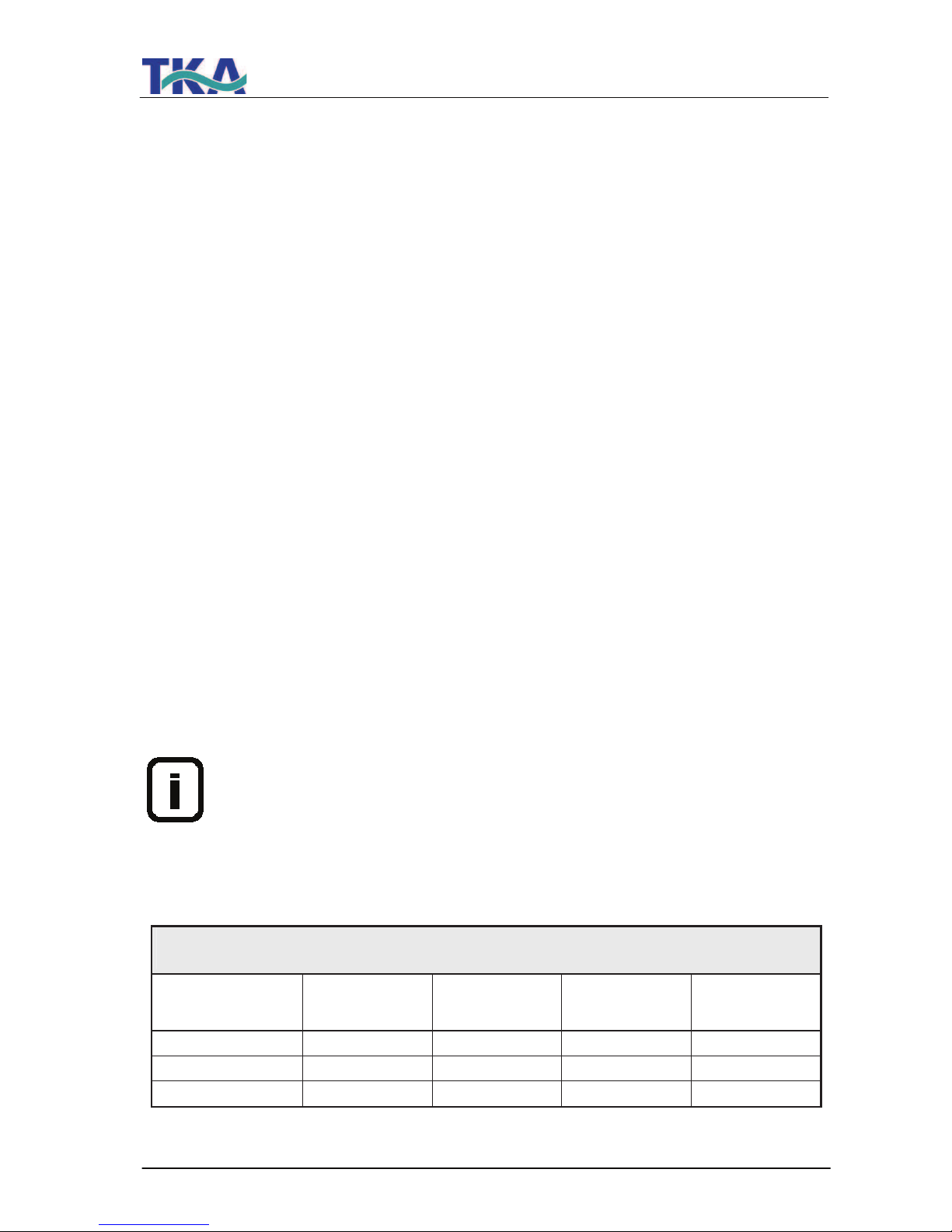
Concentrate flow for LabTower EDI
Check and adjust at least 1x monthly
System Permeate-
flow
[l/h)
Concentrate-
flow RO
[l/h]
adjustable
up to
[%]
Concentrate-
flow EDI
[l/h]
LabTower EDI 15 20 min. 60 40 2
LabTower EDI 30 40 min. 60 40 4
LabTower EDI 45 50 min. 60 40 5
Page 16

LabTower EDI
Ultrapure water system
16
Your Ultrapure water system is equipped with automatic flushing. Flushing is carried out when
the system is switched on, at the end of each production, and also every 12 hours. For this,
rinsing solenoid valve (V3) is opened and the strong flow of water across reverse osmosis
module (F2) then flushes coarse particles and other contaminants away from the surface of the
membranes and carries them with it to drain.
This automatic flushing has a positive effect on the service life of the reverse osmosis module.
An additional advantage of automatic flushing is that it prevents bacterial growth from occurring
in the reverse osmosis module when the system is at a standstill for a long time. For this
reason, we highly recommend that you leave the system switched on over the weekend and
during holiday times, so that the 12 hour flush can effectively guard against bacterial growth.
Page 17

LabTower EDI
Ultrapure water system
17
8. The installation area
The following criteria must be taken into consideration when choosing the installation area.
# Minimum temperature in the installation area: + 2°C - +35oC.
# The surface that your pure water system is to be stood on must be strong enough
to support it (for weight, see "Technical Specifications").
# A floor drain with waste pipe of DN 50 size (38.5 mm id) is required. Should this not be
available, then a water watcher (article no.: 16.0129) must be installed to protect against
damage from water flooding!
# An unrestricted gravity flow of concentrate to the floor drain is obligatory.
# An electrical socket appropriate to the voltage given on the type plate of the system must
be positioned directly alongside the system. The safety fuse must be appropriate for the
power required (see "Technical Specifications").
# Ensure that there is sufficient working room around the system.
# An R ¾“R male thread tap water connection which can be shut off must be installed in
the direct vicinity of the system.
# Easy access to this must be ensured.
Page 18
LabTower EDI
Ultrapure water system
18
9. Putting into operation
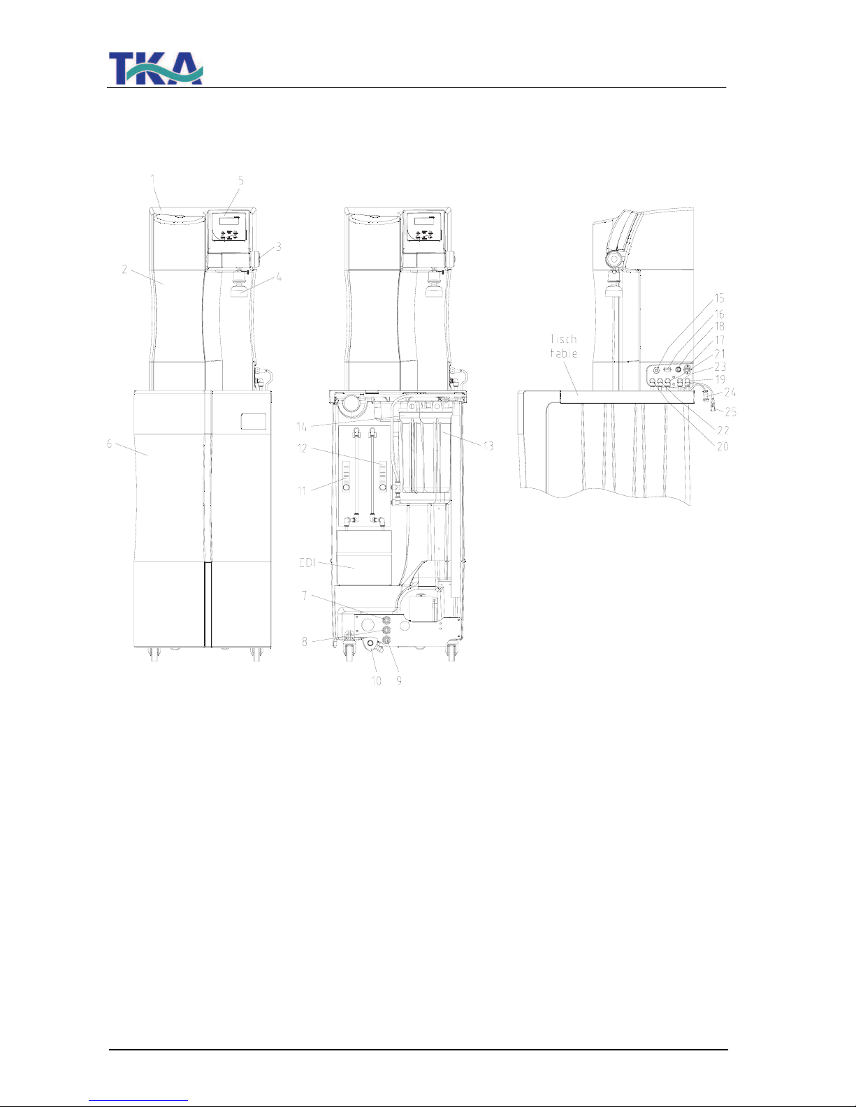
1) LabTower EDI Ultrapure water
system
2) Front hood, removable
3) Rotary knob for pure water
dispensing/dispensing valve
4) Ultra filtration capsule (option)
5) Operating unit
6) Front cover, storage tank
7) Feedwater inlet
8) Concentrate outlet
9) Pure water outlet
10) Residual water drainage
11) Product flow rate meter
12) Concentrate flow rate meter
13) Pretreatment
14) Sterile or fine filter
15) Power supply 230V/50Hz
16) Printer connector
17) Power supply EDI 230V/50Hz
18) Power supply for the pressure
pump/tank
Level control connector
19) Feedwater connector Ø8 mm
20) Permeate connector Ø8 mm
21) Pure water connector (in) Ø8 mm
22) Concentrate connector Ø8 mm
23) Pure water connector (out) Ø8 mm
24) Power supply connector for the
pressure pump/tank
Level control connector
25) Power supply EDI 230V/50Hz
Page 19
LabTower EDI
Ultrapure water system
19
1. Place the Ultrapure water system on the table of the storage tank. Connect the hoses
positioned at the table by putting the connectors in with the appropriate connections (19-23) at
the equipment.
2. Remove the covering hood (6) of the storage tank.
3. Turn the filter housing of the pre-treatment (13) loosely. Insert the pre-treatment unit con-
tained when assembling (hardness stabilization, pre-filter and connector) into the filter
housing and screw this again firmly (see chapter „Change of the pre-treatment “).
4. In the case of use of the optional sterile or fine filter you turn the filter housing (14) loosely.
Insert the filter into the filter housing and bolt this on again.
5. Connect the Ø8 – ¾“ female thread feedwater hose supplied to the feedwater inlet (7) of
the storage tank and to a water tap that can be turned off. The connecting hose is marked
“Feedwater“.
6. Connect the Ø8 concentrate hose supplied to the concentrate outlet (8) of the storage
tank and to the drain provided on-site. The concentrate hose is marked „Concentrate“.
Caution! The concentrate must be able to flow under free gravity fall to the drain!
7. Plug the 4-pin plug of the level control system (storage tank), marked „Niveau“, in the 4-pin
socket (18) of the Ultrapure water system and screw the milled nut of the plug tight.
Connect the plug (power supply EDI, 230 V), marked “EDI 230V”, to coupling (17) of the
Ultrapure water system. Fix the plug by firmly pressing the clamp.
8. Screw the optional ultra filtration capsule (4) into the withdrawal tap G1/4 “.
9. Now fit the hose of the Ø8 mm sterile overflow to the overflow on the back of the tank and
connect it to the drain.
10. Ensure that residual water drainage (10) is turned closed.
11. Check the feedwater pressure; it must be within the permissible pressure range
(see Technical specifications).
Before you now switch the system on, read through the rinsing out
procedure for reverse osmosis membranes packed with preserving
agent in the „Rinsing the membrane“!
12. Plug the line plug in and switch the Ultrapure water system on with the on/off key on the
operating unit (5).
13. Check that all connections are leak-tight.
14. Replace the covering hood on the storage tank.
After a short rinsing phase, your system begins to produce pure water into the storage tank.
Page 20
LabTower EDI
Ultrapure water system
20
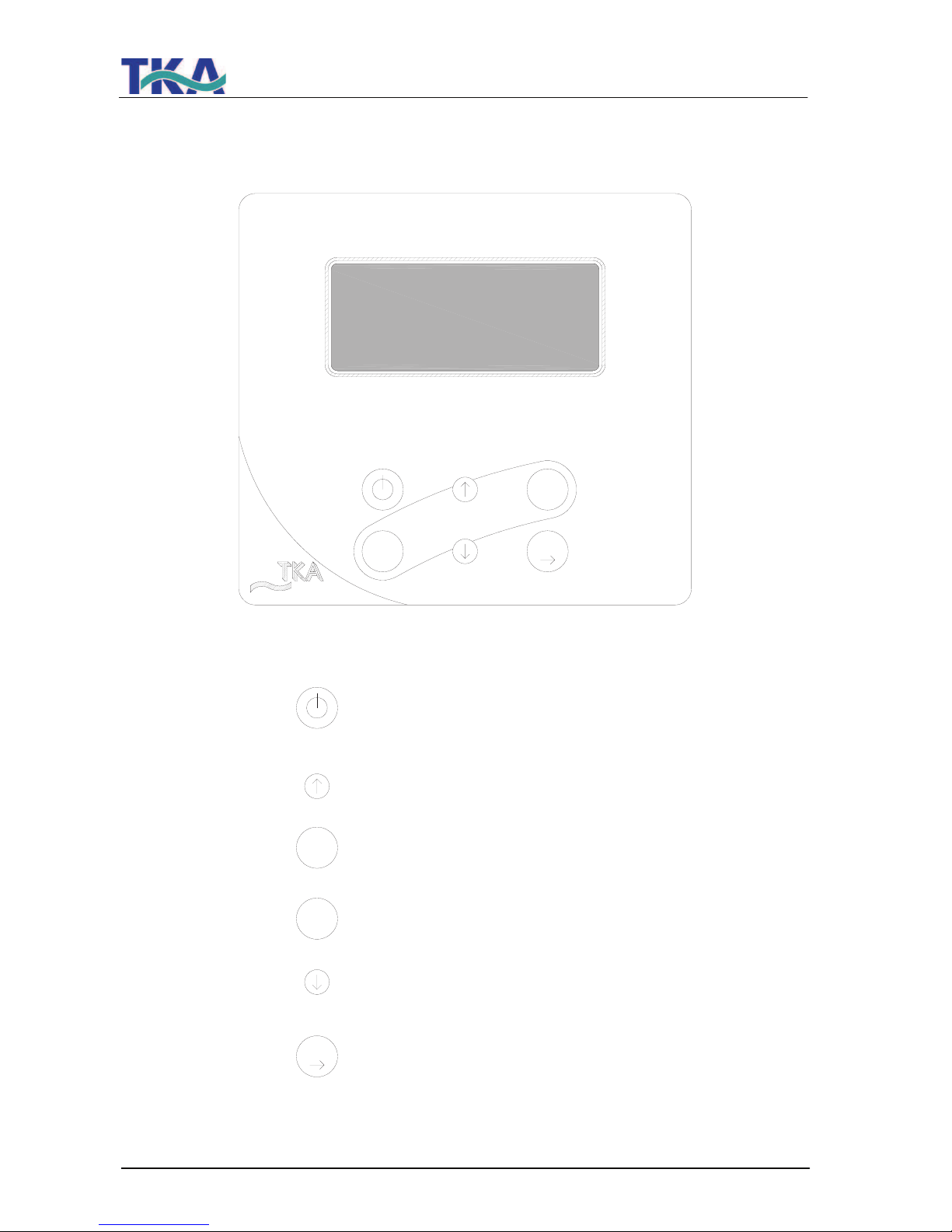
10. Operating elements
INTERVAL
menu
enter
NONSTOP
Switches the UV-lamp on or, in the menu,
allows you to select the position in a number
that you wish to change
Switches "Interval" operation on or, in the menu,
decreases a value on display
UV
Switches the menu to the next menu
point
Confirms the value shown in a menu
point
Switches "Nonstop" operation on or, in the menu,
increases a value on display
Switches the system on or off
menu
INTERVAL
UV
TKA-Pacific
Production 70%
0,100 µS/cm
18,5°C UV/TC
NONSTOP
enter
Page 21

LabTower EDI
Ultrapure water system
21
11. System control
General information
When the ON/OFF key is pressed, the system starts running either in the operating mode or in
the stand-by mode, according to the float switch.
The operating mode and the volume contained in the tank are shown in line 1 of the display and
the measured value of the permeate is shown in line 2.
Should a fault exist, then a fault message is given out across the potential-free output and is
shown in line 4 of the display. In the case of several simultaneous faults, then they are
alternately displayed.
11.1 User menu
All of the measured values, operating times and limiting values that are relevant for the user can
be set and read in this menu.
A press on the menu-key brings you into this menu. Each further press on the menu-key moves
you on from one menu prompt to the next.
Settings can be changed with the arrow keys and, when the appropriate value has been set, be
confirmed by pressing the Enter-key, which also takes you to the next menu prompt.
To simplify changing settings, a press on the UV-key allows you to select a certain number in a
numerical value that you wish to change. The arrow-keys can then be used to set a number
from 0 to 9 at this selected position.
11.1.1 Permeate conductivity:
A single press on the menu-key allows the permeate conductivity to be read and the limiting
value for the permeate conductivity to be set. Should this limiting value be exceeded, then the
"Lim.val.permeate" fault message is displayed flashing in the 4th line of the display.
(Measuring point LF 2)
Limiting value setting range: 0.1 – 150.0 µS/cm
Basic setting: 50 µS/cm
Settings above 150.0 µS/cm result in the limiting value being switched off. The word
"Off".appears in the display.
The display shows:
Permeate
12.0 µS/cm
Lim.val.permeate
50.0 µS/cm
Page 22
LabTower EDI
Ultrapure water system
22
11.1.2 Product water conductivity:
A second press on the menu-key allows the product water conductivity to be read and the
limiting value for the product water conductivity to be set. Should this limiting value be
exceeded, then the "Lim.val. EDI" fault message is displayed flashing in the 4
th
line of the
display.
(Measuring point LF 3)
Limiting value setting range: 0.1 – 150.0 µS/cm
Basic setting: 5 µS/cm
Settings above 150.0 µS/cm result in the limiting value being switched off. The word
"Off".appears in the display.
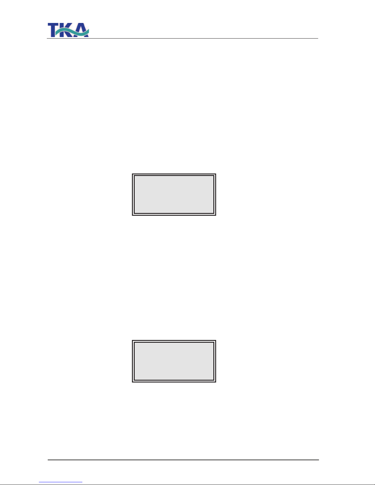
The display shows:
EDI
0.1 µS/cm
Lim.val. EDI
5.0 µS/cm
11.1.3 Ultrapure water limiting value:
A third press on the menu-key in this menu allows the ultrapure water limiting value to be set.
Should this limiting value be exceeded, then the "Lim.val.ultrapure" fault message is shown
(Measuring point LF 1).
Limiting value setting range: 0.055 – 9.999 µS/cm
Basic setting: 0.1 µS/cm
Settings above 9.999 µS/cm result in the limiting value being switched off. The word
"Off".appears in the display.
The display shows:
Lim.val.pure w
0.1 µS/cm
Page 23
LabTower EDI
Ultrapure water system
23
11.1.4 Operating hours:
A fourth press on the menu-key in this menu allows the operating hours of the UV-lamp and the
reverse osmosis pump to be displayed. The operating hours counter for the UV-lamp registers
the total length of time for which the lamp was switched on. When the maximum operating time
is reached, the "UV-time" fault message is triggered. The limiting value is set in the OEM menu.
There is no limiting value for the reverse osmosis pump.
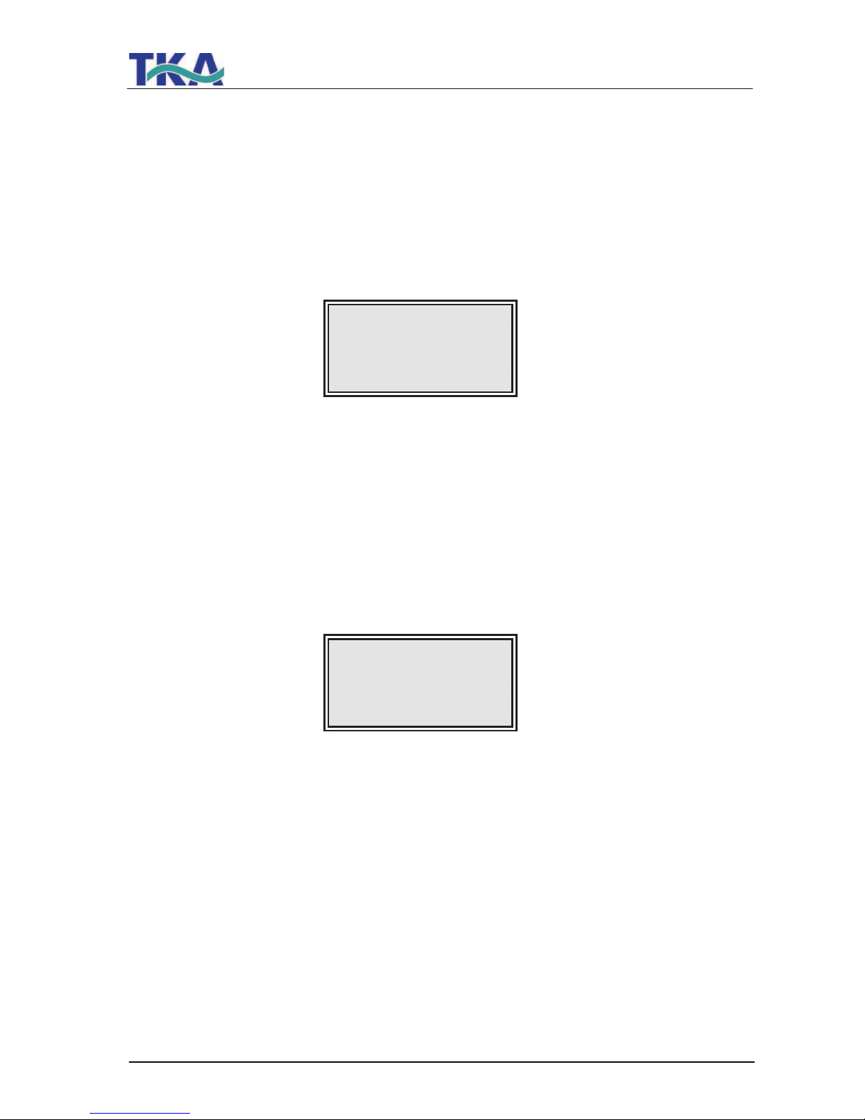
The display shows:
UV-Time
0000 h
RO Time
0000 h
12.1.5 Pretreatment operating hours:
A fifth press on the menu-key in this menu brings the operating hours of the pre-treatment
cartridge to display.
The limiting value for this operating time is set in the UV menu. The fault message that is
displayed when the limiting value is exceeded is "Pretreatment".
The operating hours of the pretreatment are counted whenever the reverse osmosis pump is
running.
The display shows:
Pretreatment
0000 h
11.1.6 Cleaning:
A sixth press on the menu-key in this menu allows cleaning to be carried out should there is a
need for it. The cleaning process is triggered by pressing the Enter-key. The pump then starts
and the inlet solenoid valve and the rinsing solenoid valve open for a period of 60 seconds.
During cleaning, no faults or measured values are displayed. When the cleaning process has
finished, the system is in the last operating mode (operating or stand-by).
The remaining cleaning time is displayed during cleaning.
Page 24
LabTower EDI
Ultrapure water system
24
The display shows:
Rinse ?
Press Enter
During cleaning, the display shows:
Rinse
30 sec.
11.1.7 Disinfection:
(not active in this version)
The display shows:
Disinfection
Press enter
11.1.8 Fault storage:
A eighth press on the menu-key in this menu calls the fault storage prompt. Confirmation of this
with the Enter-key allows the fault storage to be looked through. The display can show two
faults at once, each with time and date. Pressing an arrow key allows previous or following
faults to be displayed.
Pressing the menu-key or the Enter-key returns the system to the last operating mode.
The display shows:
Error history
Press enter
Page 25
LabTower EDI
Ultrapure water system
25
The fault storage display shows:
14.03.04 14.30
Lim.val.permeate
14.03.04 15.30
Pretreatment
11.1.9 Unlocking the system:
An ninth press on the menu-key in this menu brings you to the “Code” menu. To prevent
unauthorized access to the settings in the system control, changes to the settings can only be
carried out when the correct code from the Assignment Table that follows is entered and
confirmed with the Enter-key. The unlocking remains active for 5 minutes. Each access via the
code is typed out by the printer (RS 232), complete with date, time and abbreviated code
number (“Code 0001” corresponds to code 150, “Code 0002” to code 250 etc.).
The display shows Menu-point F:
Code
Press enter
0000
Code numbers can be assigned to individual persons according to the Assignment
Table that follows on the next page.
Remove this page from the Operating Instructions and store it where it is safe from
unauthorized viewing.
Page 26

LabTower EDI
Ultrapure water system
26
Page 27
LabTower EDI
Ultrapure water system
27
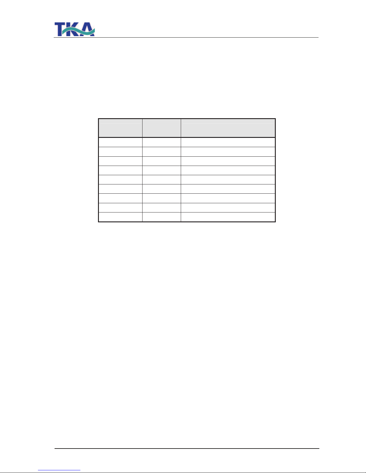
Assignment Table
for code numbers allowing the system to be unlocked
Code no.
Printer
output
Person
150 0001
250 0002
350 0003
450 0004
550 0005
650 0006
750 0007
850 0008
950 0009
Page 28

LabTower EDI
Ultrapure water system
28
Page 29
LabTower EDI
Ultrapure water system
29
11.2 OEM menu
Basic settings and limiting values can be changed in this menu.
To make changes in the OEM menu , the system control must previously be unlocked (see
"Unlocking the system").
Calling the OEM menu:
Simultaneous pressing of the Interval-key and the Nonstop-key calls the OEM menu. Following
this, the prompt "OEM menu Press enter" appears. When this is confirmed with the Enter-key,
the first menu prompt can be worked on. To simplify changing settings, press the UV-key to
select the number in a value which you want to change. Using the arrow keys now allows a
number from 0 to 9 to be entered at that position.
A press on the menu-key takes you to the next menu prompt.
The OEM menu prompt display shows:
OEM Menu
Press enter
11.2.1 Maximum temperature:
A single press on the menu-key:
The maximum temperature to which the system can be exposed can be set in this menu. When
this temperature is exceeded, the "max. Temperature" fault message is triggered. Settings
above 50 °C cause the limiting value to be suppressed and the word „off“ appears in the
display. It is shown in the 4th line of the display.
Basic setting: 50 °C
Setting range: 1 - 50 °C
The display shows:
OEM Menu
max. Temp
50 °C
Page 30
LabTower EDI
Ultrapure water system
30
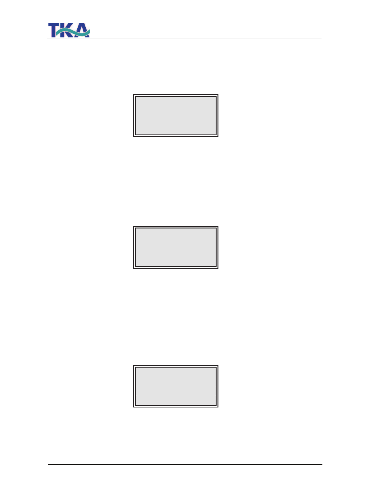
11.2.2 Disinfectionszeit:
A second press on the menu-key:
(not active in this version)
The display shows:
OEM Menu
Disinfect. time
30 min.
11.2.3 Recirculation time:
A third press on the menu-key:
The recirculation time is shown in this menu.
Basic setting: 15 min.
Setting range: 1 - 30 min.
The display shows:
OEM menu
Recirc. time
15 min.
11.2.4 Rinsing time:
A fourth press on the menu-key:
The rinsing time is set in this menu.
Basic setting: 0.5 sec.
Setting range: 0.1 - 30 sec.
The display shows:
OEM Menu
Rinse time
0.5 sec.
Page 31
LabTower EDI
Ultrapure water system
31
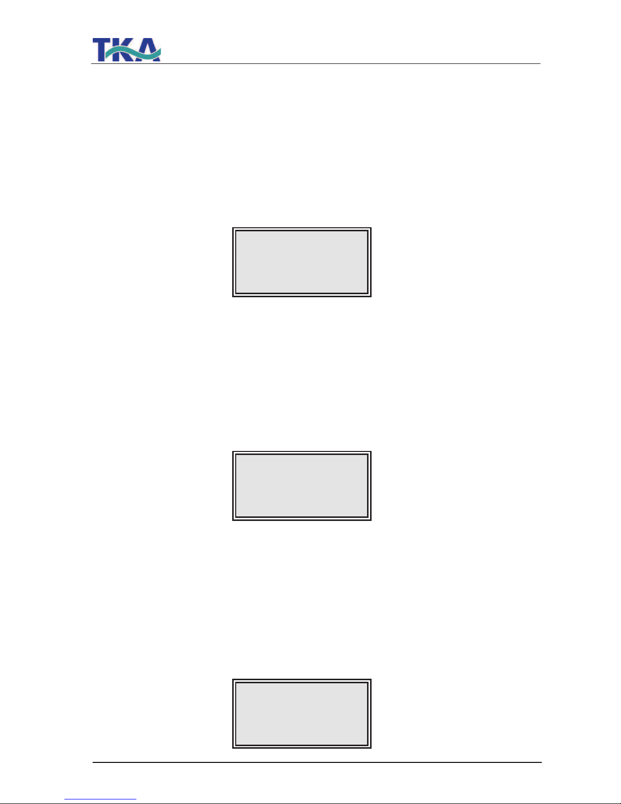
11.2.5 Interval rinse time:
A fifth press on the menu-key:
The interval rinse time is set in this menu. Rinsing is carried out for this time period when the
operating mode is changed, between stand-by and operation and every 12 hours.
Basic setting: 2 sec.
Setting range: 1 - 30 sec.
The display shows:
OEM menu
Rinse Interval
2 sec.
11.2.6 Real-time clock:
A sixth press on the menu-key:
The real-time clock is set in this menu.
Basic setting: The actual date
Setting range: 1 - 12 months, 1 - 31 days, 0 - 24 h, 0 - 60 min.
The display shows:
OEM Menu
Day 30 Month 12
Year 2006
Hours 12 min.30
11.2 7 Sending interval:
A seventh press on the menu-key:
In this menu, the sending interval for transmissions of measured values and fault messages to
the RS 232 interface is set.
Basic setting: 8 hours
Setting range: 0.5 - 12 hours
The display shows:
OEM Menu
Send interval
8 h
Page 32
LabTower EDI
Ultrapure water system
32
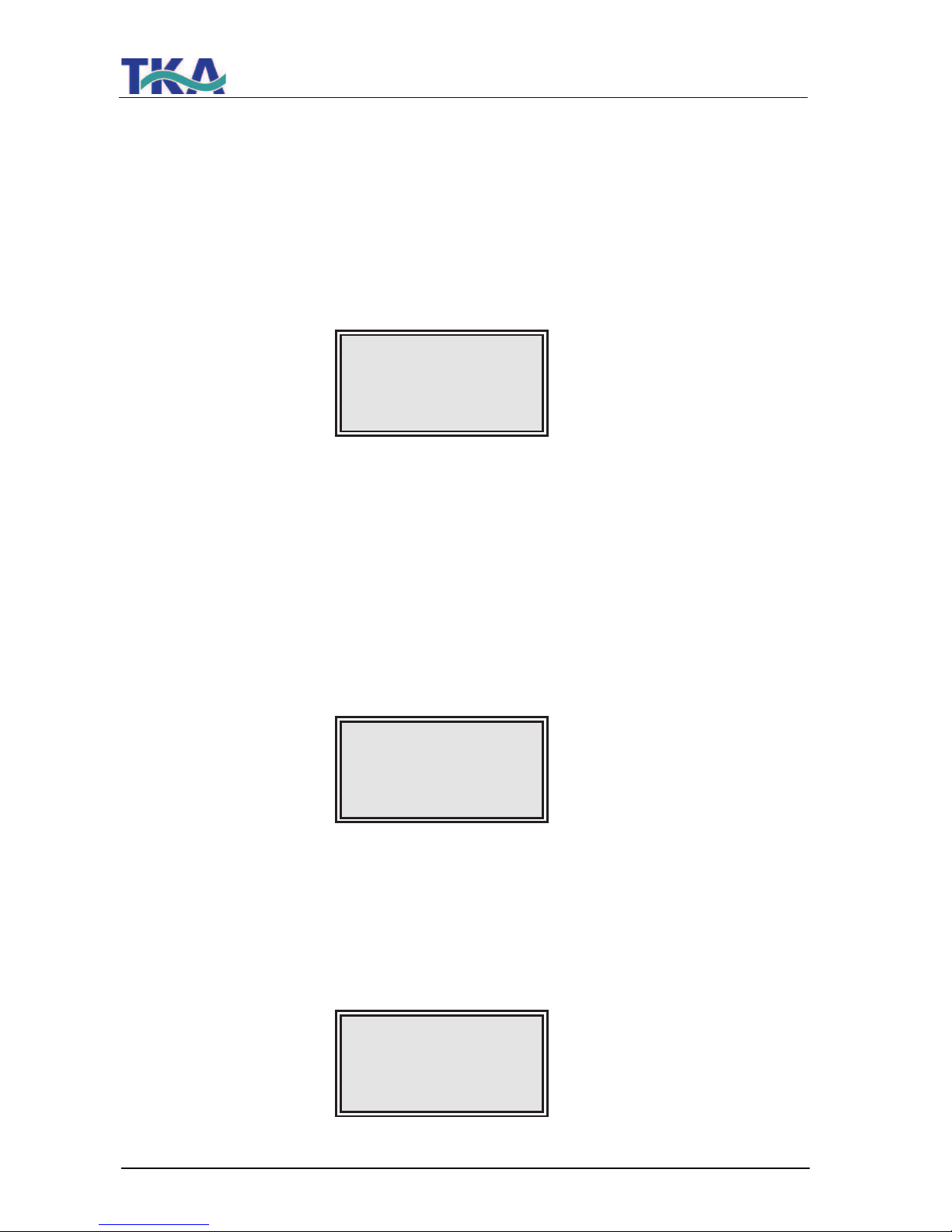
11.2.8 Language:
An eighth press on the menu-key:
The language in which texts are displayed is set in this menu. Choice of English, German or
French.
Basic setting: English
The display shows:
OEM menu
Language
English
11.2.9 Switching units:
A ninth press on the menu-key:
In this menu, a choice can be made as to whether the specific electric resistance or the
conductivity is to be displayed.
Basic setting: Conductivity µS/cm
Setting range: Conductivity µS/cm,
Specific electric resistance M! cm
The display shows:
OEM menu
µS/cm / M! cm
µS/cm
11.2.10 Switch off of temperature compensation:
A tenth press on the menu-key:
Basic setting: on
Setting range: on, off
The display shows:
OEM Menu
Temp. Comp.
on
Page 33
LabTower EDI
Ultrapure water system
33
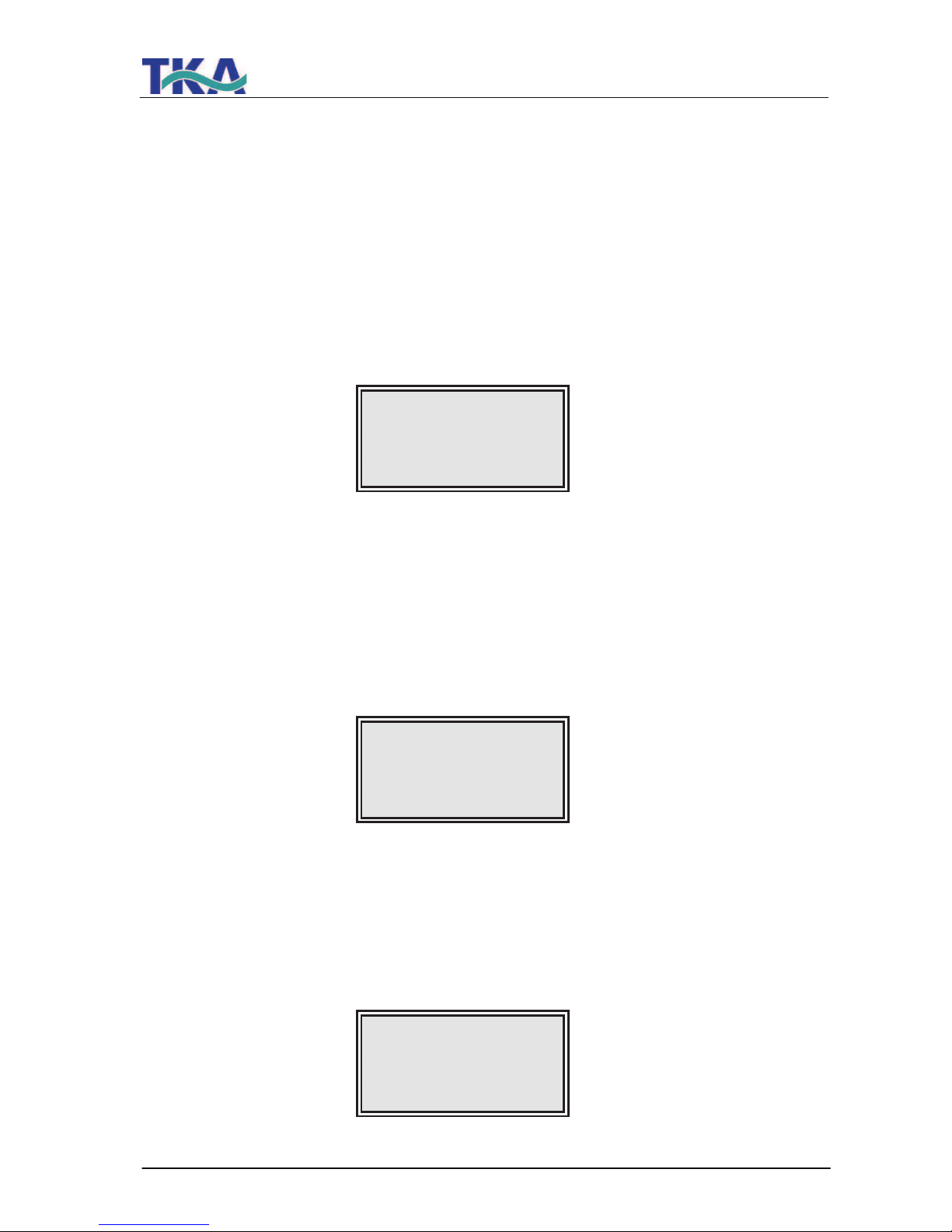
11.2.11 Adjusting the circuit hysteris of the float switch:
An eleventh press on the menu-key:
Basic setting: Off: 100 %
On: 85 %
Setting range: Off: 25 - 100 %
On: 0 - 85 %
With a setting over 100 % for the upper switching point, the display of the tank level is switched
off, so that this setting therefore shows whether an analogue or a digital float switch is installed.
The display shows:
OEM Menu
Off: 100 %
On: 85%
11.2.12 Programme choice UPW/ PW/ EDI:
A twelfth press on the menu-key:
The grade of the equipping of the system can be set in this menu to differentiate between UPW,
PW and versions.
Basic setting: EDI
The display shows:
OEM Menu
Version
EDI
11.2.13 Entering the type and serial number of the system:
In this menu, the type and serial number of the system can be entered. They are then printed as
headline on every print-out. The following types of system can be entered:
Pacific PW / Pacific UP / Pacific UPW / Pacific AFT / Pacific EDI
The display shows:
OEM Menu
Type Pacific EDI
S.Nr.: 9999/04
Page 34

LabTower EDI
Ultrapure water system
34
11.3 Printer output
The printer allows various parameters to be recorded. There are 3 different kinds of message:
- Standard message
- Code message
- Fault message
11.3.1 Standard message:
Here a record opf all measured values is printed out in dependence on the sending interval.
Such a complete dats set is also printed out during NONSTOP operation.
Print out:
e.g.: 01.06.07 09:39
Pacific EDI
S.No. 9999/04
TC on UV off
LF1= 0.062 µS/cm
LF2= 9.2 µS/cm
Temp.= 11.5 °C
11.3.2 Code message:
Whenever a code number is entered in the controls and confirmed with the Enter-key, then the
code input is immediately printed out.
For code identification, see the „Assignment Table for code numbers allowing the system to be
unlocked”.
Print-out:
e.g.: 01.06.07 10:17
Pacific EDI
S.No. 9999/04
Code 0001
11.3.3 Fault message:
Should a fault message be shown in the display, e.g. the ultrapure water limiting value, then the
fault message is printed out at the end of the sending interval.
Print-out:
e.g.: 01.06.07 16:15
Pacific EDI
S.No. 9999/04
Lim.value.ultrapure
Page 35
LabTower EDI
Ultrapure water system
35
12. Maintenance
Your system requires regular, proper and professional maintenance.
We recommend that you close a service contract to ensure that the necessary maintenance
work is carried out.
You then have the certainty of a high operational safety and reliability.
The service protocol appended to the service contract serves for certification that maintenance
work specified in the contract has been carried out by TKA or a service company authorized by
TKA.
When your system is to work reliably for a long time, it must
be checked,
serviced and cared for at regular time intervals in accordance with these
operating instructions!
For this reason, the operating instructions must be readily available to operating
and maintenance staff at all times, and be carefully followed!
Please observe that, in accordance with the general terms and conditions of TKA
company which are the basis for both parties, the guarantee loses its validity
when the customer or a third party improperly installs, maintains
, repairs,
operates, or alters the system, or operates it in an environment which does not
fulfil the installation conditions specified by TKA.
Any maintenance work which should become necessary during the validity of the
guarantee is only to be carried out by TKA, or by a customer service which is
expressly authorized by TKA to do this.
The operating staff assigned is committed to carry out daily/weekly checks.
During the agreed term of validity of the guarantee, maintenance is to be carried
out weekly according to the maintenance record sheet supplied with the operating
instructions.
In so far as the maintenance protocol is not kept up-to-date, or is improperly kept,
i.e. without the necessary establishment of data, then the system is deemed to be
improperly maintained and the guarantee becomes invalid.
The calibration of the conductivity display is only to be carried out and recorded
by TKA customer service.
Cleaning and disinfection of supply tanks, piping, filter housings etc. is performed
for reasons of hygiene and has no effect on the technical condition of the system.
These components must be cleaned and disinfected whenever algae/slime are
detected inside them or at least once yearly.
The pretreatment included in the system must be replaced two times in the year
with the 5µm + activated carbon combi-cartridge (art.-no. 06.5203) and with the
hardness stablizer (art.-no. 06.5453).
When inspection or maintenance work is to be carried out on electrical
equipment, then the system is to be separated from the mains by unplugging the
line plug and securing it against inadvertent plugging in again. Such work is only
to be carried out by trained, skilled electricians.
Page 36
LabTower EDI
Ultrapure water system
36
12.1 Rinsing the membrane
Rinsing out preservative solution:
According to the mode of delivery, the system may be supplied filled with a solution containing a
preservative. When putting the system into operation, the permeate must be run to drain for at
least 3 – 4 hours after switching to production.
For rinsing and disinfecting, the permeate hose must be drawn off of the outlet of
the Ultrapure water system so that the EDI cell does not suffer damage.
Connect a hose from the assembly kit to lead off the contaminated permeate from
the permeate outlet of the Ultrapure water system to drain.
Unplug the pure system „Power supply EDI“ plug.
Now carry out the rinsing procedure.
When the rinsing and disinfecting process has finished, fit the permeate hose
(storage tank) back to the permeate outlet of the Ultrapure water system and
re-connect the EDI power supply.
Cleaning the membrane:
Automatic rinsing lengthens the service life of your reverse osmosis module. Coarse particles
and other contaminants are swept away from the membrane surface during this rinsing process.
The rinsing phases so ensure the longest service and optimal ultrapure water quality.
Leave your ultrapure water system on over the weekend and during
holiday times. Only then can the 12-hourly rinse operate and ensure
that your reverse osmosis module is not subject to bacterial growth
during standstill periods.
Should the performance of your module drop because operation of the system without
appropriate pretreatment has resulted in blockage of the membrane, it may well be that your
module can be reconditioned.
Reconditioning and disinfection of the module is only to be carried out by authorized service
personnel on-site or by sending the module to the manufacturer of your system, whereby
exposure to frost must be avoided.
Page 37
LabTower EDI
Ultrapure water system
37
12.2 Replacing the pre-treatment
*
*
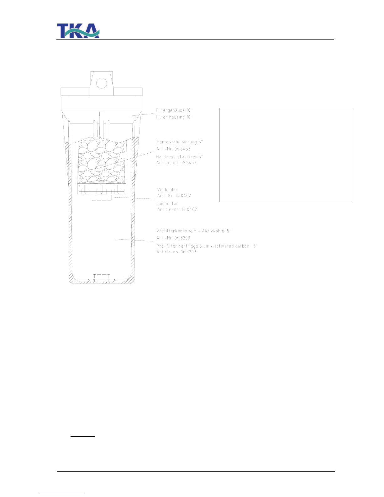
1. Remove the covering hood from the
storage tank.
2. Open the residual drainage of the
storage tank, see section “Views and
connections“, until the Ultrapure water
system starts to operate.
3. Stop the supply of feedwater to the
Ultrapure water system.
4. Switch the system off.
5. Turn the residual drainage to close it.
6. Screw off the pre-treatment filter
housing, see the „Views and
connections“ section.
Caution!
The filter housing is still filled
with water.
7. Removed the spent pre-treatment unit.
8. Connect the new prefilter cartridge and
hardness stabilizer together by plugging
them with the connector, as shown in
the diagram above.
9. Screw the filter housing back on.
10. Open the supply of feedwater to the
system.
11. Check that the filter housing does not
leak.
12. Switch the Ultrapure water system on.
13. Replace the covering hood on the
storage tank.
Your Ultrapure water system is now again ready for use.
*
Hinweis:
Bei vorgeschaltetem Enthärter oder Mix Multi
Filter wird nur eine Vorfilterkerze 5 µm +
Aktivkohle 10" (Art.-Nr. 06.5201) eingesetzt.
Notice:
With pre installed Softeners or Mix Multi filter is
only a prefilter 5 µm + active carbon 10"
(Article-no. 06.5201) inserted.
Page 38
LabTower EDI
Ultrapure water system
38
12.3 Replacing the RO-membrane
! Remove the line plug from the mains socket.
! Remove the back panel.
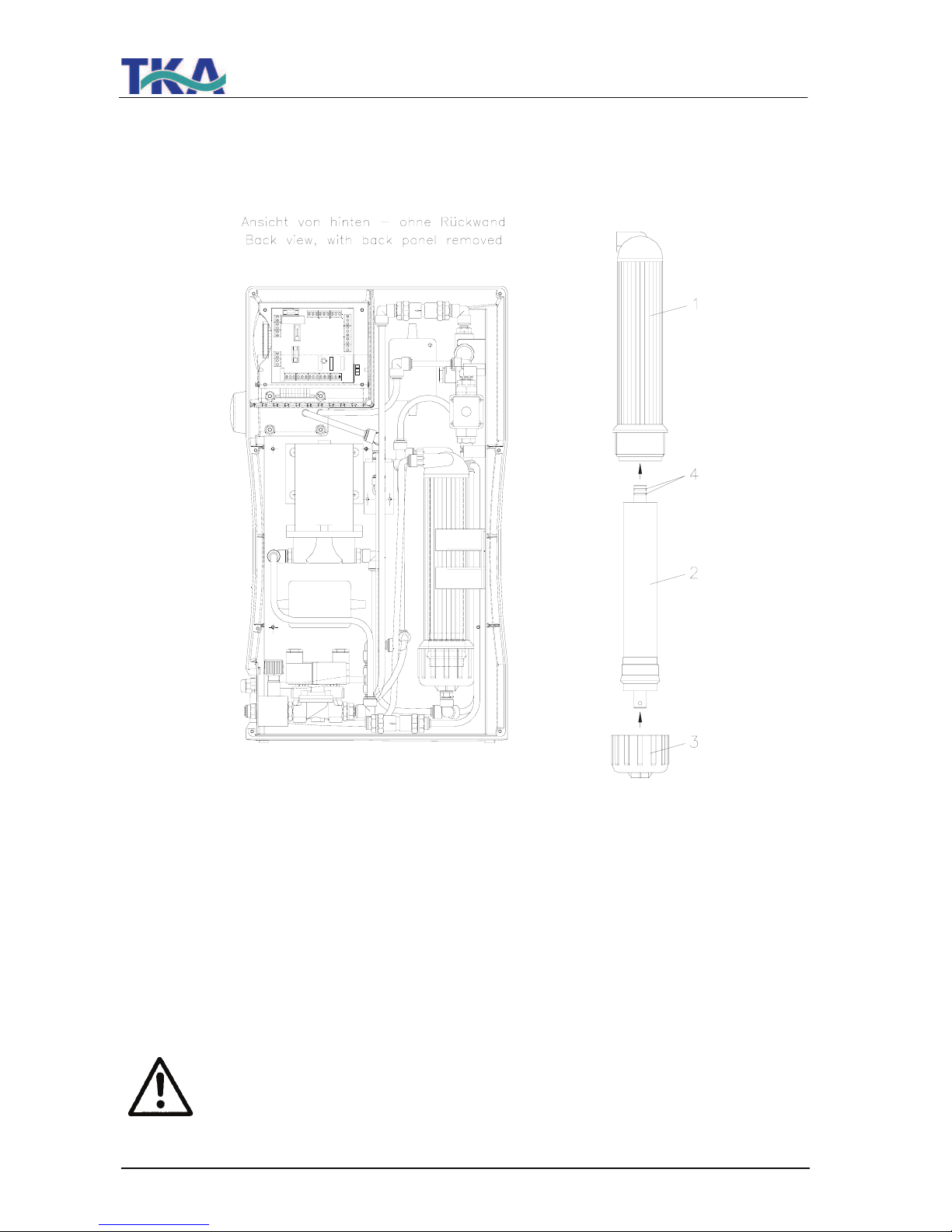
! Undo all hose connections to the RO-module pressure tube (1).
! Remove the pressure tube from the holding sleeves.
! Open the cap nut (3) on the pressure tube and remove the RO-membrane (2).
! Insert the new RO-membrane in the pressure tube (1) with the two O-rings (4) on the
permeate tube of the RO-module in the direction shown by the arrows.
Inserting the RO-membrane the wrong way round would result in certain
destruction of the membrane!
Page 39
LabTower EDI
Ultrapure water system
39
12.4 Changing the Ultrapure water module
The Ultrapure water module must be replaced as soon as the
maximum limiting value set for the ultrapure water is exceeded or
when the “Change cartridge” message is shown in the display.
Proceed as follows to replace the Ultrapure water module:
1. Switch the system off.
2. Shut off the supply of feedwater.
3. Open the dispensing valve until the flow of water stops, then re-close it.
4. Remove the cartridge cover.
5. Disconnect the quick-connects on the feedwater inlet and purified water outlet of the
Ultrapure water module, then close the inlet and outlet with the stoppers which you
have kept for later usage.
6. Draw the used Ultrapure water module out from the guide and insert the new module.
7. Remove the stoppers from the new Ultrapure water module and store them for later
use.
8. Plug the quick-connects correctly onto the new Ultrapure water module so that they
audibly engage.
9. Replace the cartridge cover.
10. Open the supply of feedwater.
11. Switch the system on again.
12. The Ultrapure water system is now again at your availability to produce ultrapure
water.
Page 40
LabTower EDI
Ultrapure water system
40
12.5 Disinfection procedure
Disinfection should be regularly carried out, at the latest when the Ultrapure water module is replaced.
A TKA disinfection cartridge (article no.: 09.2201) is required for disinfection of the system.
MICRO-Chlor disinfectant (article no.: 09.2202) are to be used as disinfectant.
To avoid possible health hazards, please take notice of the information
given in the safety data sheet supplied in the packaging when handling
MICRO-Chlor!
Page 41
LabTower EDI
Ultrapure water system
41
To disinfect the Ultrapure water system proceed as follows:
1. The Ultrapure water system must be in the “Stand by” operating mode.
2. Switch the system off.
3. Turn off the feedwater supply to the system.
4. Open the dispensing valve until water no longer runs out and then close it.
5. Remove the covering hood from the storage tank.
6. Remove the cartridge cover from the system (refer to the “Changing the ultra pure
water module” section in the LabTower EDI operating instructions”).
Take off the quick connects from the feedwater and ultra pure water side of the ultra
pure water module and close the connectors with the stoppers that you have saved.
7. Remove the ultra pure water module.
8. Take hold of the disinfection cartridge and screw out the stopper from the lid of it. Fill
water in through the opening until the cartridge is full and then pour the contents of a
can of MICRO-Chlor in.
Important: The cartridge must be completely filled with water for successful
disinfection.
9. Screw the stopper back in the lid of the disinfection cartridge and connect up the
cartridge in the system (as described in the “Changing the ultra pure water module”
section in the operating instructions for the system).
10. Turn the feedwater supply on.
11. Switch the Ultrapure water system on and allow it to run for 2 hours in “Stand by”
operating mode.
12. Now open the residual drainage (dispensing valve) of the storage tank and discard all
of the water that runs out. Close the residual drainage.
13. Fill the storage tank until the “Stand by” operating mode has been reached and empty
the tank as in 12. Repeat this process a second time.
Do not take any water from the dispensing valve or the storage tank during
disinfection.
14. Switch the system off.
15. Remove the disinfection cartridge and fit in the new ultra pure water module.
16. Switch the system off.
17. Finally replace the covering hood on the storage tank.
Page 42
LabTower EDI
Ultrapure water system
42
18. The Ultrapure water system is now again at your availability to produce ultrapure
water.
Always install a new filter element in the pretreatment and a new ultrapure water module following disinfection of the system.
The 0,2 µm sterile vent filter can be autoclaved if required.
Replacement parts:
Ultrapure water module Article no: 09.2005
Sterile vent filter, 0,2 µm Article no: 06.5003
or
Sterile vent filter, 0,2 µm + CO
2
(option) Article no: 06.5002
Page 43
LabTower EDI
Ultrapure water system
43
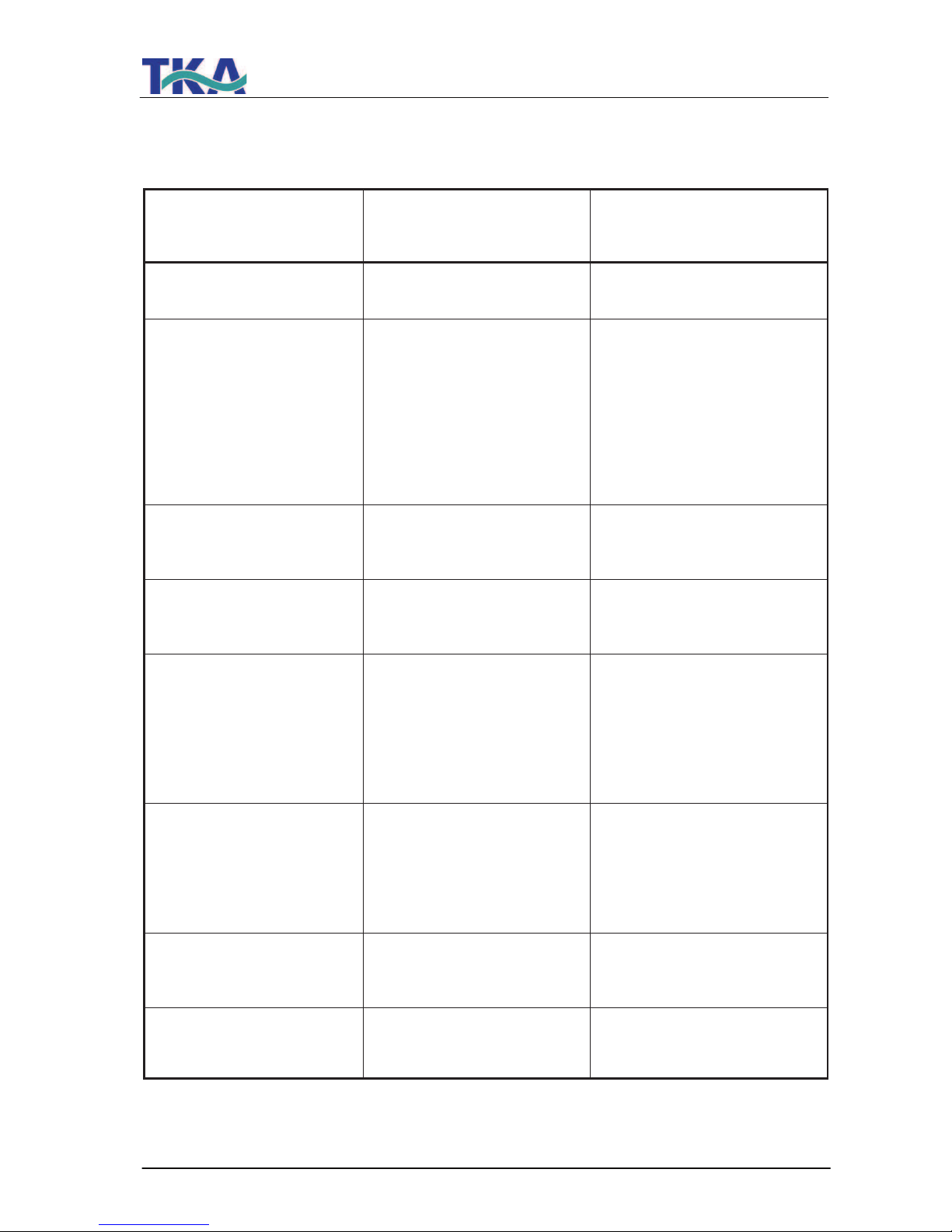
13. Trouble shooting
Fault
Cause
Remedy
The system does not start
- No supply of power
- Connect to power supply
No dispensing possible
- Feedwater tap is closed
- Feedwater and rinse water
connections the wrong way
round
- Feedwater pressure < 1.5 bar
- Open feedwater tap
- Reverse the connections
- Increase feedwater pressure
Conductivity too high
- Ion exchanger capacity is exhausted
- Replace ion exchanger with a
new one
System control no longer
reacts
- Improper operation
- Remove line plug for 5
seconds
Water flows out
- Leaky hose connection
- Feedwater pressure > 6 bar
- Check and hose connection and stop the leak
- Install a pressure reducer, possibly operate via the emergency supply
Permeate flow too low
(-15%)
- Blocked membrane
- Precompression too low
- Feedwater temperature fluctuates
- Clean the membrane
- Increase precompression
Wrong time or date
- Time zone
Summer/Winter time
- Reset time and date
Wrong language
- Wrong language set
- Set wanted language
Page 44
LabTower EDI
Ultrapure water system
44
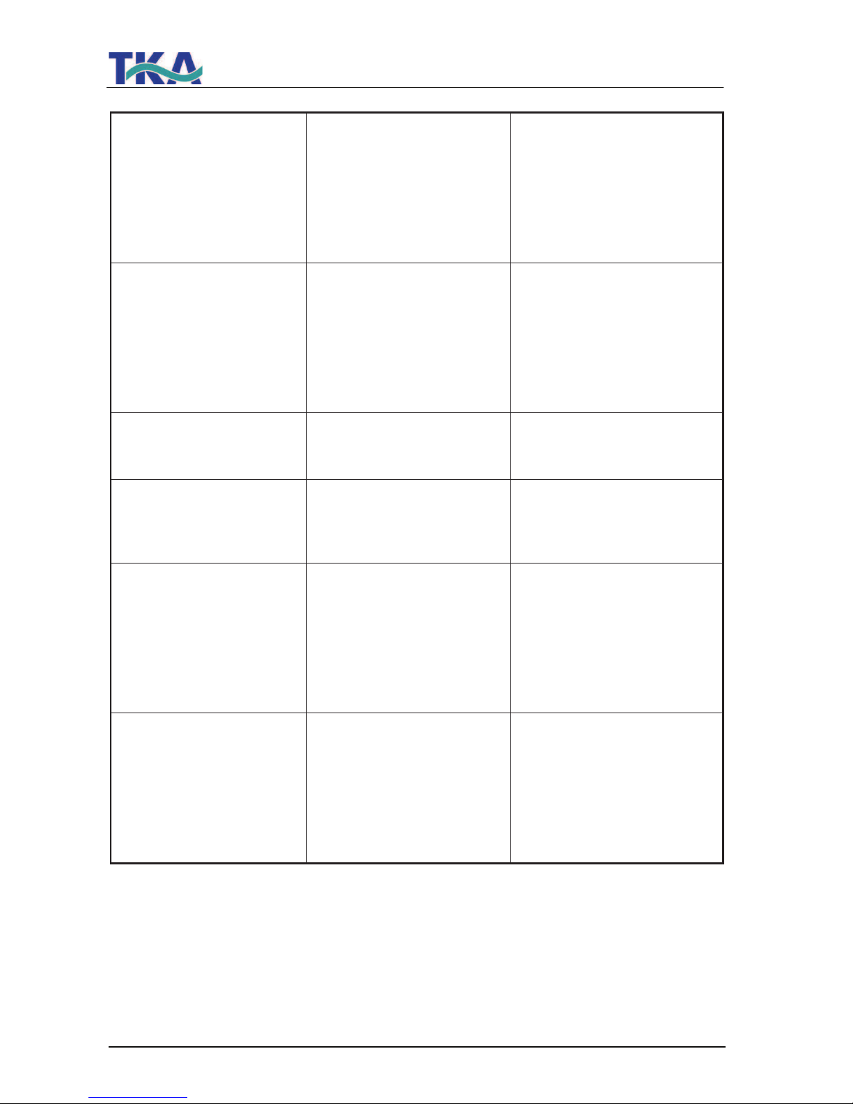
Fault message:
Lim.val.permeate"
- The conductivity of the permeate is too high
- The limiting value is set too
low
- The membrane is blocked
- Check the pre-treatment
- Check and re-adjust the
limiting value setting
- Replace the membrane
Fault message:
Lim.val.EDI"
- The conductivity of the product water is too high
- The limiting value is set too
low
- The EDI cell is damaged
- Check the permeate
conductivity
- Check and re-adjust the
limiting value setting
- Replace the EDI cell
Fault message:
"Lim.val.pure w"
- The limiting value is set too
low
- Check and re-adjust the
limiting value setting
Fault message:
"UV-time"
- The operating hours of the UV-lamp have been
exceeded
- Replace the UV-Lamp (art.- no. 09.2002) and set back the operating hours counter
Fault message:
"Measuring cell LF1"
- Cable break at the measur ing cell
- System control defect
- Ultrapure water conductivity
outside of measuring range
- Replace the measuring cell
- Replace the system control
- see "Lim.val.pure w"
Fault message:
"Measuring cell LF2"
- Cable break at the measur ing cell
- System control defect
- Feedwater conductivity outside of measuring range
- Replace the measuring cell
- Replace the system control
- see "Lim.val.permeate"
Page 45

LabTower EDI
Ultrapure water system
45
Fault message:
"Measuring cell LF3"
- Cable break at the measur ing cell
- System control defect
- EDI conductivity outside of
measuring range
- Replace the measuring cell
- Replace the system control
- see "Lim.val.EDI"
Fault message:
"Measuring cell Temp."
- Cable break at the measur ing cell
- System control defect
- Replace the measuring cell
- Replace the system control
The address to contact should you need service:
TKA Wasseraufbereitungssysteme GmbH
Stockland 3
D-56412 Niederelbert
Tel. No.: +49 (0)26 02 1 06 99-0
Fax. No.: +49 (0)26 02 1 06 99-50
Internet:
www.tka.de
E-Mail: [email protected]
Page 46
LabTower EDI
Ultrapure water system
46
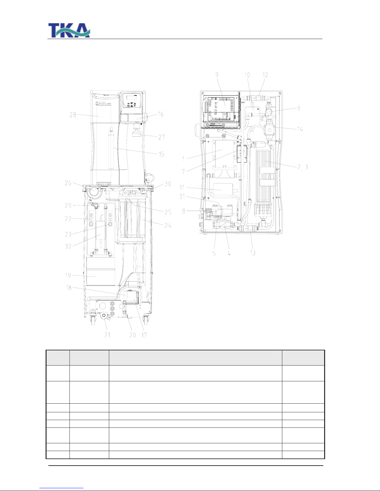
14. List of replacement parts
No. R+I No. Article designation Art.-no.
1 P1 Pressure booster pump RO for system 15 L/h
Pressure booster pump RO for system 30+45 L/h
19.0046*
19.0050*
2,3 F2 Reverse osmosis membrane, for system 15, L/h 2x
Reverse osmosis membrane, for system 30+45, L/h 2x
Module pressure tube, for system 15 – 45 L/h 2x
22.0046*
22.0087*
22.0047
4 V1 Inlet solenoid valve 15.0103*
5 V3 Rinsing solenoid valve 15.0103*
6 QIA300 Measuring cell permeate 16.0126
7 QIA302
TIA500
Measuring cell ultrapure water 26.0014
8 V2 Pressure hold valve 15.0060
9 Microprocessor system control, complete 26.0023
Page 47
LabTower EDI
Ultrapure water system
47
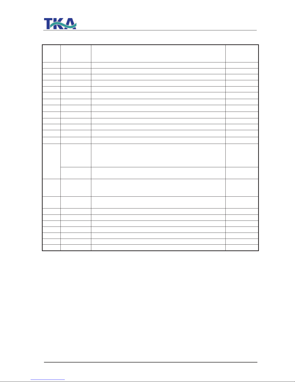
10
Transformer for:
Pressure booster pump P1, system 15 l/h
Pressure booster pump P1, system 30+45 l/h
16.0195
on request
11 Transformer for recirculation pump 16.0195
12 V4 Check valve 15.0009
13 V5 Check valve 15.0019
14 V6 Recirculation solenoid valve 15.0014*
15 UV1 UV-Lamp in system (option) 09.2002
16 V7 Dispensing valve 25.0068
17 PS200 Pressure switch 15.0058*
18 P2 Circulation pump 19.0046*
19 EDI EDI-Cell 22.0098
20 V11 Check valve 15.0009
21 V10 Dispensing tap 14.0250
22 FI400 + V8 Flowmeter, product (EDI) incl. regulation valve 15.0123
23 FI401 + V9 Flowmeter, concentrate (EDI) incl. regulation valve 15.0124
F1 Pre-treatment consisting of:
Prefilter cartridge 5µm + Activated carbon, 5“
Hardness stabilizer, 5“
Connector
06.5203
06.5453
14.0402
24
With pre installed Softener or Mix Multi filter
Prefilter cartridge 5µm + Activated carbon, 10
06.5201
25 F6 Fine filter 1µm-10“
or
Sterile filter 0.1µm-10“ (option)
06.5101
06.5557
26 F5 Sterile vent filter 0.2µm or
Sterile vent filter 0.2µm + CO
2
Adsorber (option)
06.5003
06.5002
27 F4 Ultra filtration capsule (option) 09.1021
28 F3 Ultrapure water module 09.2005
29 QIA301 Measuring cell product water 26.0047
30 LIS100 Level control 16.0355
31 PS201 Pressure switch rawwater 15.0099*
32 EDI Transformer/EDI 16.0334
V12 Sterile overflow/storage tank (option) 15.0009
* Wearing part
We ask for your understanding that the guarantee we give becomes invalid when
replacement parts, accessories or consumables from other manufacturers are used, as
we have no influence on their appropriateness or quality.
Page 48

LabTower EDI
Ultrapure water system
48
15. Accessories
! UV-Lamp (in system) Article no.: 26.0013
! UV-Lamp (in tank) Article no.: 06.5006
! Sterile filter cartridge 10“ Article no.: 06.5557
! Sterile vent filter Article no.: 06.5003
! Sterile vent filter + CO
2
Adsorber Article no.: 06.5002
! Sterile overflow Article no.: 15.0009
! Sterile filter capsule 0.2 µm Article no.: 09.1003
! Ultra filtration capsule Article no.: 09.1021
16. Consumable materials:
Pre-treatment:
! Prefilter cartridge 5µm + Activated carbon, 5“ Article no.: 06.5203
! Hardness stabilizer, 5“ Article no.: 06.5453
! Connector Article no. 14.0402
! Prefilter cartridge 5µm + Activated carbon, 10“ Article no.: 06.5201
(only with upstream softener)
! Ultrapure water module Article no.: 09.2005
! Ultra filtration capsule Article no.: 09.1021
! Sterile vent filter Article no.: 06.5003
! Sterile vent filter + CO
2
Adsorber Article no.: 06.5002
! Sterile filter cartridge 1µm-10“ Article no.: 06.5557
! Fine filter 1µm-10“ Article no.: 06.5101
UV-Lamp - System:
! Replacement UV-lamp Article no.: 09.2002
! Immersion tube Article no.: 22.0063
UV-Lamp – Storage tank:
! Replacement UV-lamp Article no.: 09.5002
! Immersion tube Article no.: 22.0096
Page 49
LabTower EDI
Ultrapure water system
49
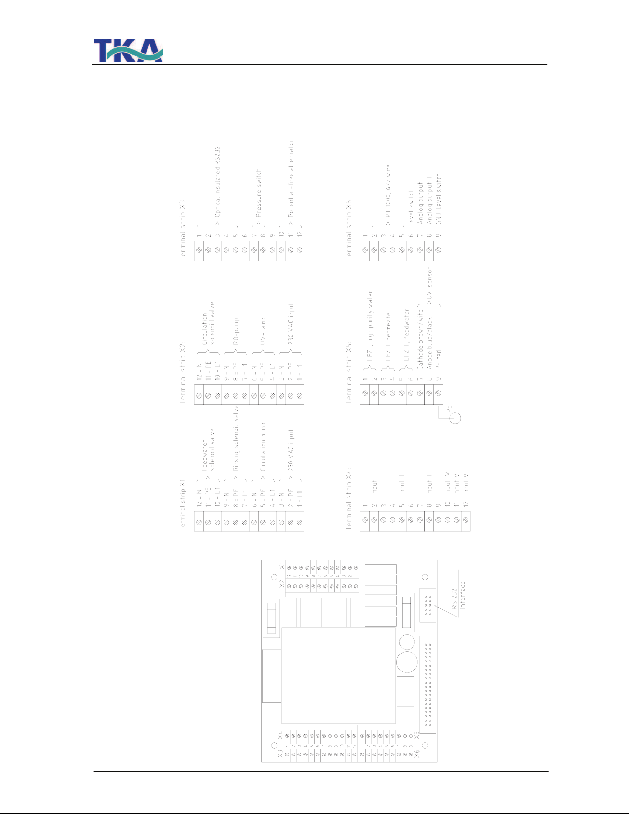
17. Terminal assignment
Page 50
Page 51
LabTower EDI
Ultrapure water system
51
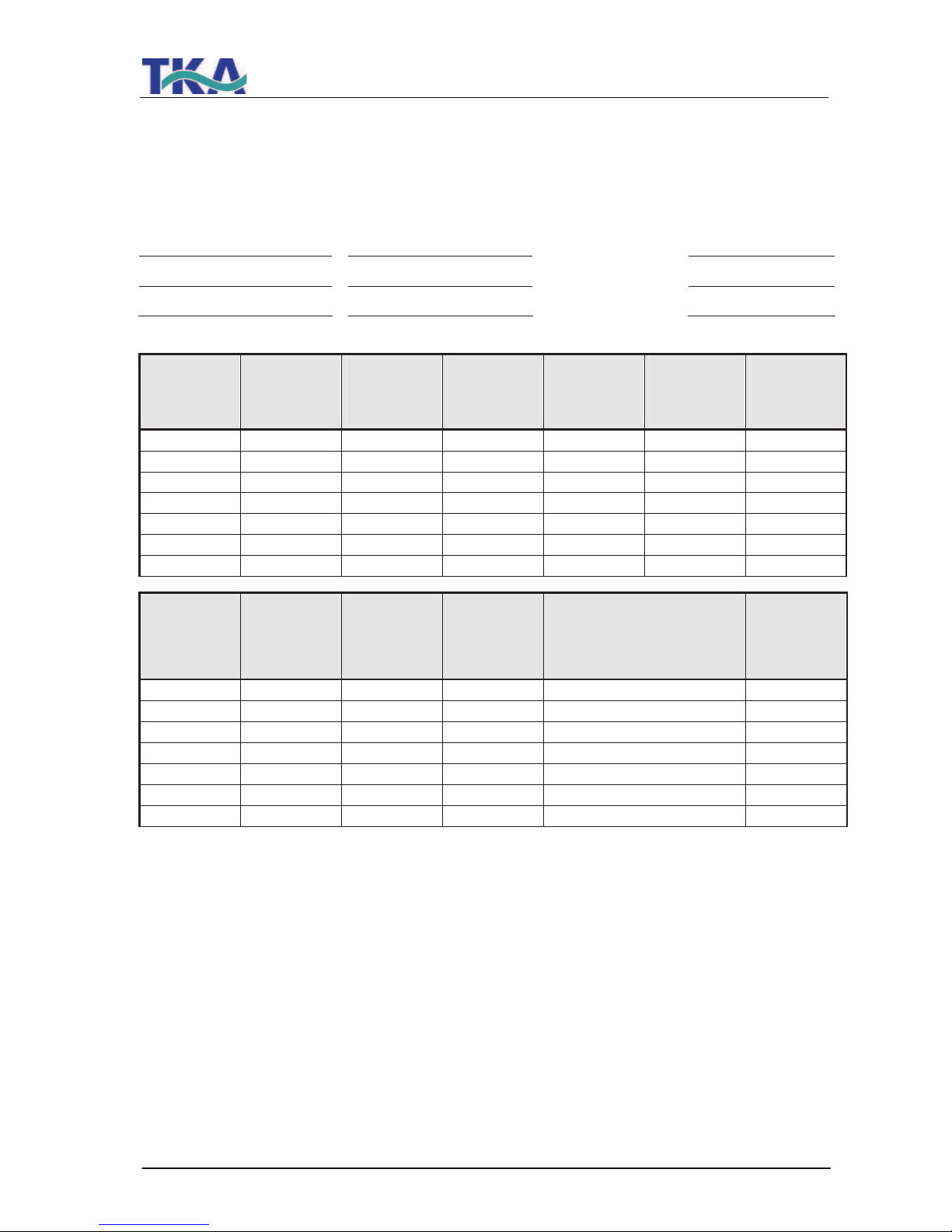
18. Maintenance record
(Please note that correct keeping of this record is a condition for the validity of the guarantee)
Customer address: Location:
System type:
Serial no.:
Year made:
Date Conductivity
Permeate
[µS/cm]
Conductivity
EDI
[µS/cm]
Conductivity
Ultrapure
water
[µS/cm]
Product
EDI
[L/h]
Concentrate
EDI
[L/h]
Operating
hours RO
[h]
Change of
prefilter
yes/no
Change of
hardness
stabilizer
yes/no
Change of
sterile filter or
fine filter
yes/no
Change of
ultrapure
water module
yes/no
Remarks Signature
Any false entry is considered to be a falsification of documents.
The following points are to be observed to ensure the quality of the system:
1 each week, record measured values
Every 3 - 6 months* - change the hardness stabilizer
Every 3 - 6 months* - change the prefilter
*According to the quality of the feedwater
 Loading...