

Page 1

T&J Models
R/C Model Designs By Jim Young
9356 Wendover Ct.
Brighton, MI 48116
www.tnjmodels.rchomepage.com
Mig-17
“
A Shark Fin on a Boomerang
The Mikoyan-Gurevich Mig-17 is the follow on of the more famous Mig-15, one of the
first successful swept-wing jet fighters. It was designed to fix any combat problems
found with the Mig-15. The result was one of the most successful jet fighters prior to the
introduction of true supersonic planes. The Mig-17 is longer than the Mig-15 and was
the first use of an afterburner in a Soviet fighter. 8000 Mig-17’s saw service from the
early 1950’s through the 1960’s by twenty countries. There are almost 30 privately
owned Mig-17’s in the United States, with several pulling airshow duties, giving many
options for color schemes.
This Mig-17 is designed around the Great Planes Hyperflow EDF unit(GPMG3910) and
the Ammo 24-45-3790 brushless motor (GPMG5185). This economical setup gives nice
EDF performance on a 4S 2200mAhr LiPo battery pack. The outline is true to scale with
the exception of larger ailerons and the position of the stab to simplify construction.
”
Copyright © 2014 Jim Young and T&J Models
Page 2

Construction
The construction of this model requires
some advanced level of modeling
experience. All of the major parts are
laser cut, and the builder is left to select
wood and hardware to complete the
model.
Materials List
The following is list of the major pieces
of wood and hardware needed to
complete the model. Additional wood
may be required.
(5) 1/16” x 4” x 36” Balsa Wing and Fin
Skins
(2) 1/16” x 1/4” x 36” Basswood Rear
Spars
(1) 1/16” x 1/2” x 36” Basswood Wing
L.E.
(1) 1/4” x 1/2” x 16” Balsa Aileron L.E.
(1) 3/16” x 1/2” x 36” Balsa Wing L.E.
(4) 3/32” x 4” x 36” Balsa Fuselage
Planking
(1) Sullivan #507 Flex Cable
(1) 1/32” x 36” Music Wire
(1) 1/4” x 24” Dowel
Tail Feathers
Mig-17
stab. The plywood provides a “joiner”
between the two halves of the stab and
slots for CA type hinges. Add a small
strip of light weight (0.5oz) glass cloth
to the center of the stab to reinforce this
joint. Taper the elevators and round the
leading edge of the stab. Bevel the L.E.
of the elevators, glue the control horns in
place, and temporarily hinge the control
surfaces.
The rudder is laminated in a similar
fashion with 1/8” balsa on both sides of
the plywood core.
The stab and elevator are 3/32” balsa
laminated around a central core of 1/64”
plywood. The grain of the balsa should
run parallel to the trailing edge of the
The fin is built up and has features to
slide on to the fuselage formers. Sand
the front of each rib to match the angle
of the L.E. Pin the ribs in place over the
plans and glue the ¼” balsa L.E. and
T.E. Glue the V6’s in place using scrap
1/16” plywood to make sure the gap is
correct. Glue the V7 fin tips in place.
Page 2 Copyright © 2014 Jim Young and T& J Models
Page 3

Plane and sand the T.E. and tip to match
the ribs.
Sheet the fin with 1/16” balsa. Remove
the fin assembly from the board and cut
an opening for the stab between V3 and
V4. Add scrap balsa blocks at the front
and rear of the slot to fit close to the
stab.
Mig-17
Wings
Prepare the top and bottom wing skins.
Edge glue two sheets of 1/16” balsa
together. Use the plans to cut the wing
sheeting leaving it slightly over sized at
the L.E. and root. For the top skin, bevel
the trailing edge of the sheeting to the
line shown on the plans.
Install the elevator flex cable as shown
on the plans. Remove the building tabs
from the ribs and sheet the other side.
Cut an opening in the sheeting between
V3 and V4. Glue the stab in place,
making sure it is square to the fin.
Temporarily hinge the rudder and glue
the control horn in place.
Glue the balsa spar box top and bottom
(SB1) to the plywood spar box sides
(SB2). Use two layers of scrap 1/16”
plywood between the sides to ensure the
spar will fit. Position R2 on the spar box
and glue it in place up against the tabs.
Slide R1 and R3 on to the spar box and
glue in place. Glue the outer spar box
top (SB3) and bottom (SB4) in place.
Sand the outboard end of the spar box to
match the L.E. Sand the front of each rib
to match the angle of the L.E. (make
right and left hand ribs).
Page 3 Copyright © 2014 Jim Young and T& J Models
Page 4

Mig-17
Pin the spar box assembly and the rest of
the wing ribs in place over the plans.
Glue the 1/16”x1/4” basswood rear spars
in place.
Glue R2A in place making sure it is
level with the board. Glue the 1/16”
balsa T.E. in place and sand the top to
match the rear spars. Glue the 1/16”
basswood sub-leading edge and
plane/sand it flush with the ribs. Note
there is a slight bend in the L.E. at R4
and it should taper slightly outboard of
R7. Glue the top sheeting in place, and
trim it flush with the L.E.
Remove the wing assembly from the
board. Use pinholes to locate R2, R4,
and R5 for the wing-fences.
Jig the wing up-side-down over the
plans. Make sure the wing is properly
pinned down and touching all of the jigs
to set the correct washout.
Glue the 1/16” plywood servo hatch
mount in place. At the L.E. make sure
Page 4 Copyright © 2014 Jim Young and T& J Models
Page 5
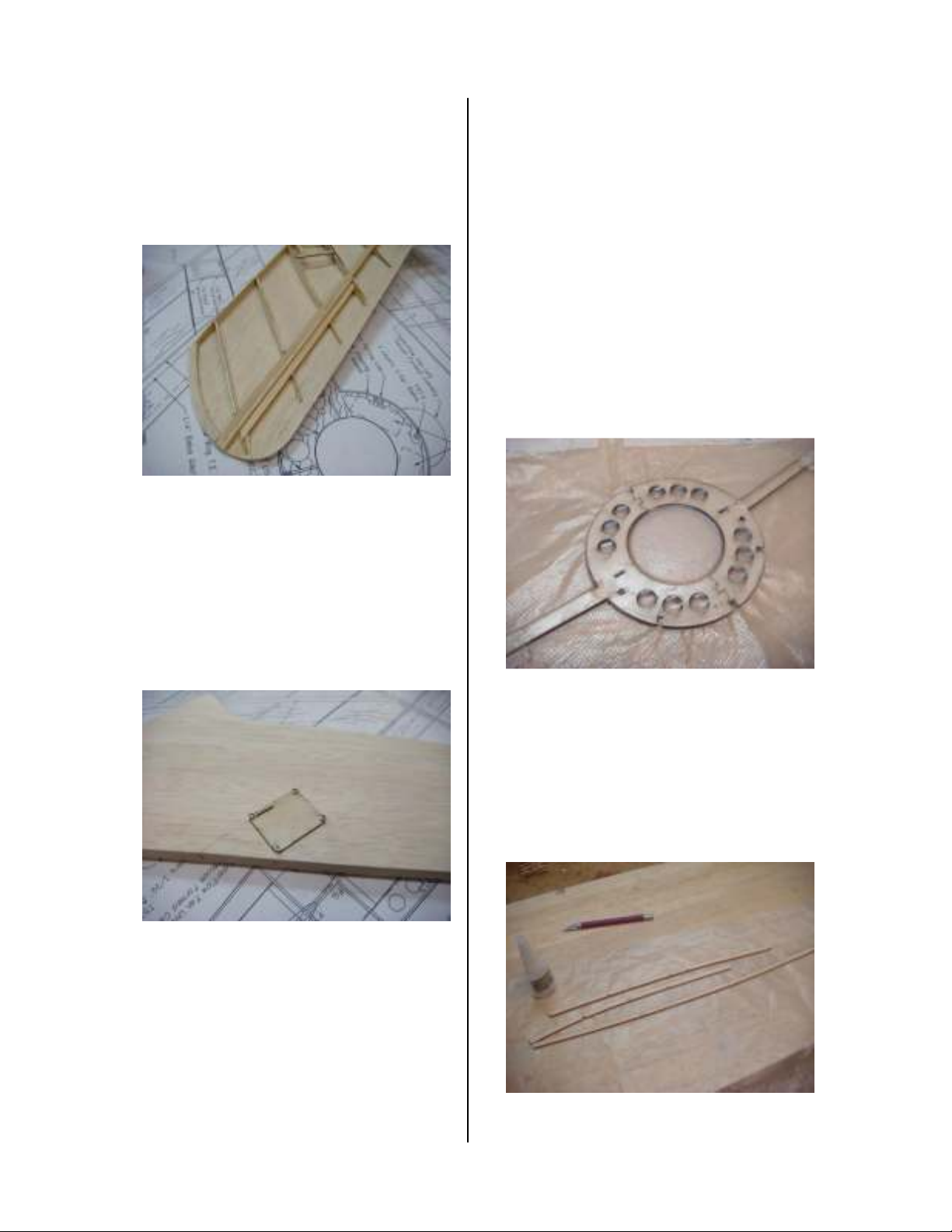
the mount is even with the surrounding
ribs. Laminate the three layer wing tip
flat, and then glue it to the top sheeting.
The top sheeting will bend to the wing
tip. Sand the wing tip to match the ribs.
Mark the location for the aileron ribs
using the marks on the plans and the
angle gauge. Sand the 1/4” balsa aileron
L.E. as shown on the plans. Glue the
aileron L.E. to the top sheeting followed
by the aileron ribs. Use pin holes to
mark the location of the aileron. Plane
the sub-leading edge flush with the ribs.
Mig-17
free from the wing. Glue the control
horn to the end of the aileron between
the top and bottom sheeting. Sand the
aileron to its final shape. The ailerons
are hinged along the top with the
covering material. The sheeting at the
wing roots will be trimmed to match the
fuselage later.
Do I have to tell you to make two wings,
a right and a left? I didn’t think so,
moving on.
Fuselage
Laminate the two F4’s together using 30
minute epoxy. Weigh them down under
something flat to ensure a straight and
strong wing spar. Glue a small piece of
light weight glass cloth on both sides of
F8 and F9 around the fin mounts as
shown on the plans.
Glue the 1/16” balsa bottom sheeting in
place. Use a pin to locate the servo hatch
mounting holes. Use the 1/16” plywood
servo hatch as a template to remove the
bottom sheeting. The aileron servo is
mounted to the hatch. Glue the 3/16”
balsa L.E. in place and sand to shape.
Locate the edges of the aileron and cut if
Page 5 Copyright © 2014 Jim Young and T& J Models
Page 6
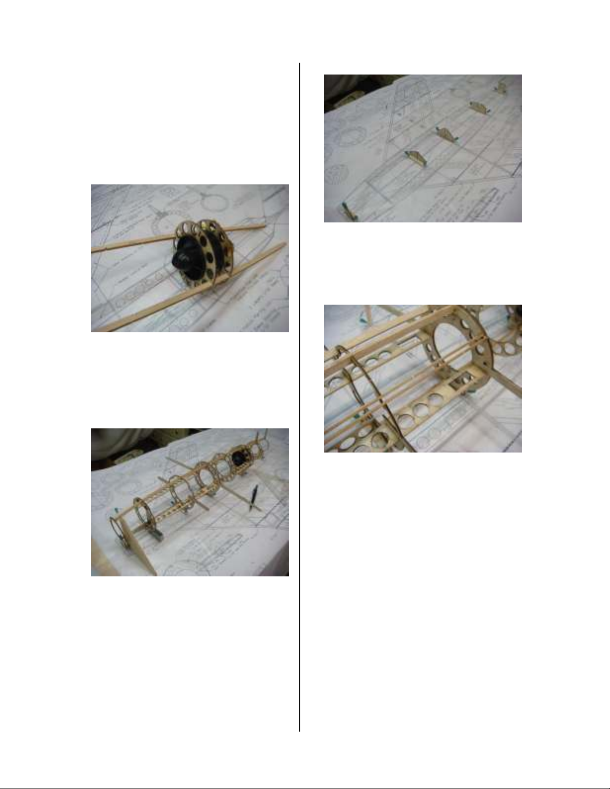
Laminate the top and bottom fuselage
stringers. Assemble and balance the fan
unit. Test run it and make sure all
screws have thread locker on them. Use
a hobby knife in a scraping motion to
round the inside inlet edge of the fan
shroud.
Glue F6 and F7 to the fan unit using the
top and bottom stringers to position
them. Use the marks on the former and
mold lines on the fan to line up the
formers.
Mig-17
Jig the fuselage over the plans and
square each former to the plans. Use
thin CA to glue the fuselage structure
together.
Dry assemble all of the fuselage formers
(F1 to F9) to the top and bottom
stringers. Use rubber bands to
temporarily hold it together. Add the
servo and battery mounts (F10 and F11).
Glue the hatch formers to the top
stringer using 1/64” plywood to space
them from F2 and F4. Glue the H1 hatch
edges in place. There should be an 1/8”
gap between these pieces. Slip wax
paper between the hatch formers and F2
and F4.
Page 6 Copyright © 2014 Jim Young and T& J Models
Page 7
Mig-17
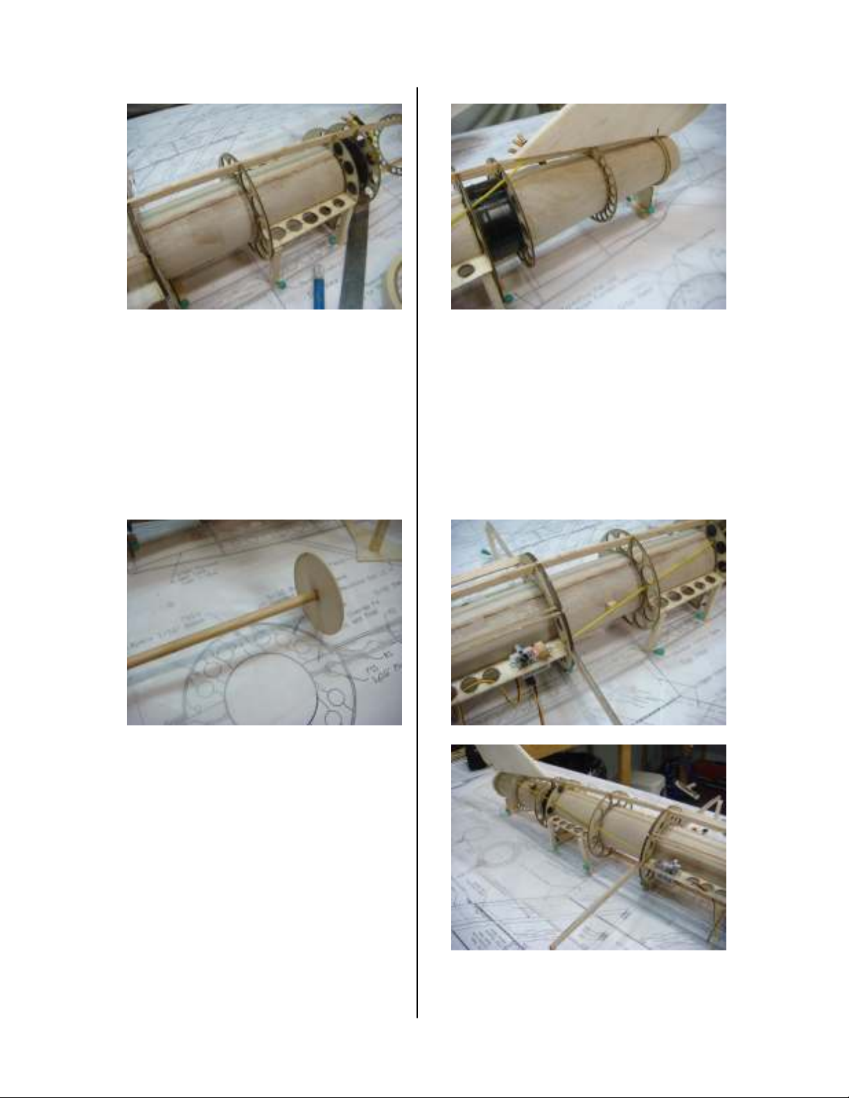
With full inlet ducting, there are
considerable forces trying to collapse it
during flight. Ensure that the duct
material is solid and has no cracks in it
and that it is securely glued to all
formers. Cut the front and rear ducts
from 1/64” plywood. The edges of the
ducts overlap 1/4” and are beveled to
provide a smooth duct.
Use the template on the plans and cut
and install the outlet duct. Make sure F8
and F9 are aligned and square to the
board.
Fit the tail assembly to the fuselage.
When satisfied with the alignment apply
a liberal amount of 30 minute epoxy and
make it permanent.
Insert the ducts in the fuselage and use
the jig mounted to a 1/4” dowel to hold
it round as you glue the seam. Double
check the alignment of the fuselage
before gluing the ducts to the formers.
Page 7 Copyright © 2014 Jim Young and T& J Models
Page 8
Use the extra outer sleeve from the flex
cable and 1/32” music wire for the
rudder linkage. Install the motor wires
and aileron servo extensions.
Use the planking template on the plans
to cut 3/32” balsa planks. This will help
reduce the amount of cutting and fitting.
Slightly bevel the edges of each plank
before gluing it in place. I’ve found that
using sandable glue along the edges and
CA to glue them to the formers makes
quick work of this task. Plank the top of
the fuselage as far as you can down each
side.
Mig-17
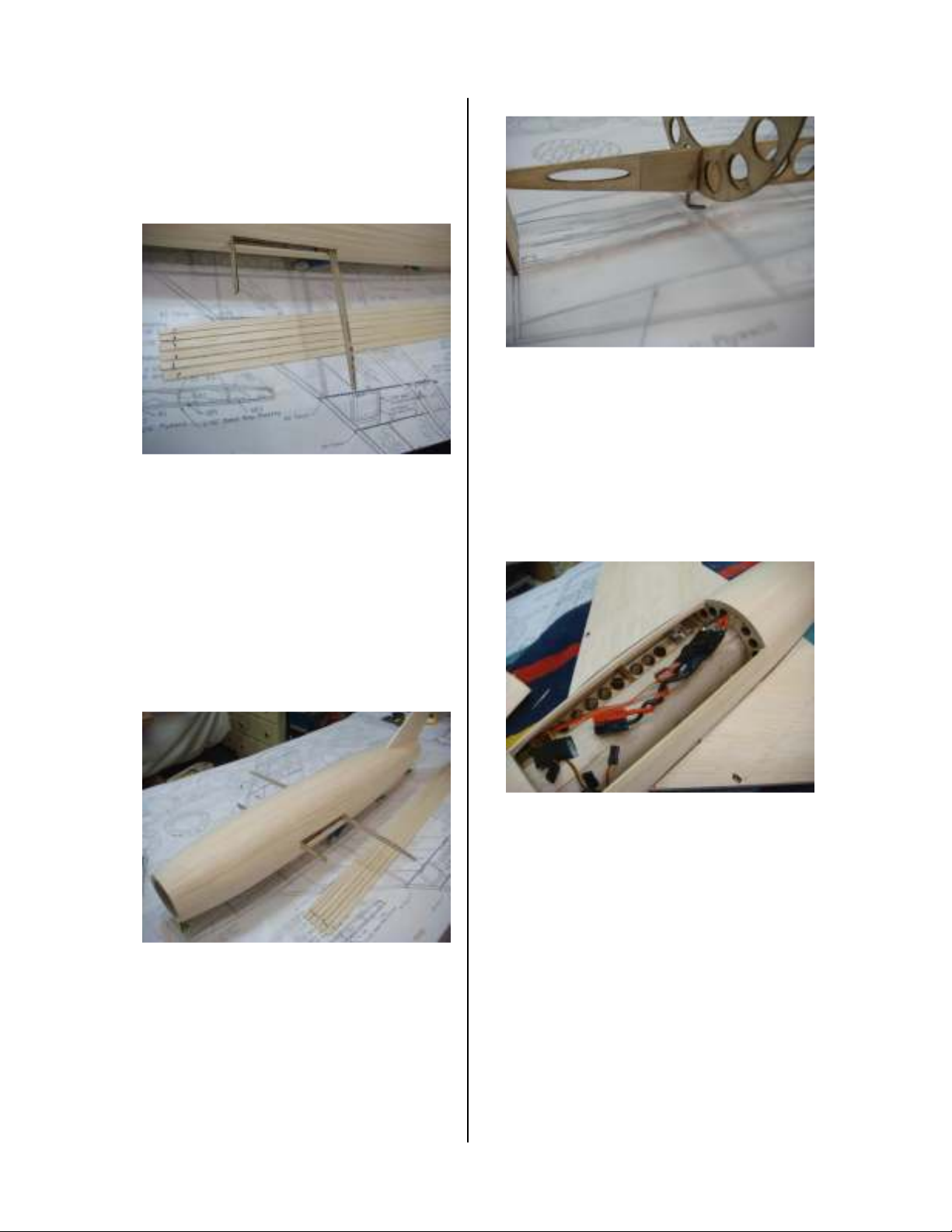
Bend the tow hook from 1/16” music
wire and epoxy it in F12. Glue 1/64”
plywood scraps to trap the tow hook in
place. Complete the fuselage planking
and sand the fuselage smooth. Cut holes
to match the aileron servo lead holes in
the wing root ribs and to clear the spar
box.
Cut partially through the planks around
hatch so you can find it later. Remove
the fuselage from the board.
Cut the hatch free and add the forward
pin and a rear locking mechanism of
your choice. Sand the planking even
with the H1’s on the hatch and H2’s on
the fuselage.
Page 8 Copyright © 2014 Jim Young and T& J Models
Page 9
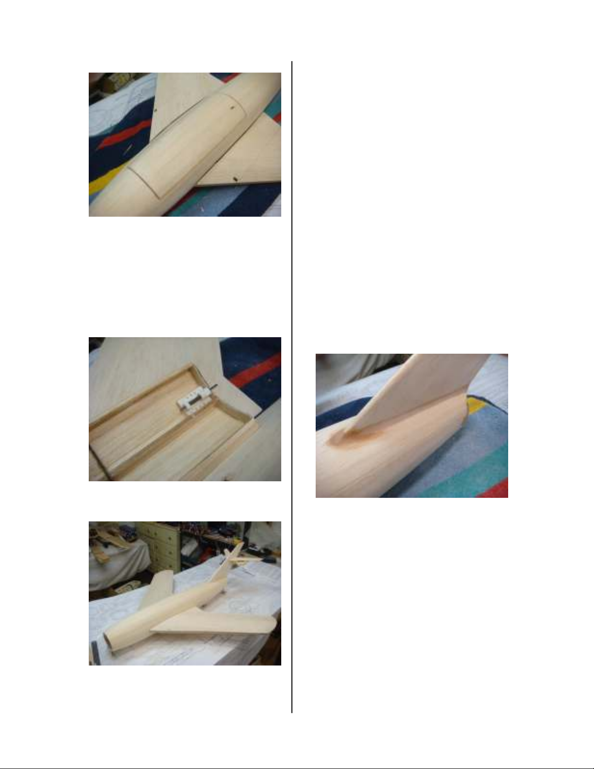
Glue a piece of 1/16” basswood to the
H1’s on the hatch and in the fuselage.
Replace the hatch and sand the
basswood edges flush with the planking.
Trim the canopy to fit the hatch. It is
glued in place after covering.
Mig-17
Slide each wing on to the spar and mark
the wing sheeting with the shape of the
fuselage. Trim the sheeting for a tight fit
to the fuselage. R1 should touch the
fuselage at F4. When satisfied with the
fit, apply 30 minute epoxy and slide the
wings in place. Jig the fuselage over the
plans and pin the wing tip jigs in place.
Double check the alignment and let it
cure overnight.
The wing fences are laminated from two
layers of 1/64” plywood. Mark the
location of the fences on the wing and
use the fences themselves to mark the
tab locations on the wing. Use a knife to
enlarge slots on the wing so the fences
fit flush with the wing. The fences can
be installed now if painting or later if
covering.
Final Assembly
Apply a small fillet around the root of
the wing, the fin, and stab. Final sand
the airframe and prepare it for finishing.
There are many color schemes that the
Mig-17 has appeared in. You can go
with traditional military silver/gray, or
the Mig-17 has become popular with
several airshow pilots and teams if you
want something more colorful. Any of
the iron on films should be fine for this
Page 9 Copyright © 2014 Jim Young and T& J Models
little EDF. Glassing and paint is also an
Page 10

option, but keep in mind the 30 oz. target
weight.
Install the radio gear, we used HS-45’s
all around. The ESC and Rx fit under
the hatch. A pair of 2Sx2200mAhr
packs are wired in series and positioned
to balance the model as shown on the
plans.
Flying
To keep the Mig-17 light, the landing
gear was omitted in favor of bungee
launching. The Great Planes Bungee
Launch Set (GPMA2885) is
recommended. The F13’s provide an
area to safely grip the Mig behind the
wing. With about 20 paces of tension on
the bungee, throttle up and release the
Mig from shoulder height. It will
accelerate quickly with very little drop
while on the bungee.
I strongly recommend that for the first
few flights you climb to altitude and do
some tests at half throttle and apply full
up elevator. The high tail position of the
Mig can cause the stabilizer to be
blanketed by the wing with too much up
elevator. If you have too much elevator
the Mig will start to tumble. If this
happens, apply half power, neutralize the
controls, and wait for the nose to drop
(hence the need to do this at altitude) and
then gently pull out. Reduce the elevator
throw as necessary.
With the light wing loading, full power
is not needed for mild aerobatics. The
stall is gentle and straightforward.
Loops, rolls, and point rolls are all
within the capabilities. With the C.G.
set as shown, inverted flight requires just
a bit of down to maintain level flight.
When the throttle is pushed the Mig
Mig-17
accelerates quickly and the vertical
performance is simply awesome. The
recommended power system will easily
push the Mig at over 100mph. You
better make sure your eyeglass
prescription is up to date, because it gets
small fast.
The Mig can be slowed down for
landings. Keep the wings level on final
and use the rudder for course
corrections. With the anhedral wing it is
easy to catch a wing tip, but the airframe
has proven to be quite durable.
I hope you enjoy your vintage jet.
Many thanks to Keith Shaw for letting
me bounce ideas off him and for his
gifted thumbs on the first few flights.
Page 10 Copyright © 2014 Jim Young and T& J Models
Page 11

Mig-17
Disclaimer
Jim Young and T&J Models accept no responsibility for crash damage and/or loss of kits, engines, accessories, etc.
incurred during operation or building of a Jim Young and T&J Model’s radio-controlled model. In most cases it is very
difficult or impossible to determine whether crash damage was actually due to radio equipment failure or to operator error.
It is impossible to guarantee product compatibility for product recommendations. We provide information and suggestions
to the best of our abilities based on the information available to us at the time. We are unable to guarantee successful
outcomes.
All of the products sold by Jim Young and T&J Models are intended for retail consumption by our customers and are not
intended for resale. We reserve the right not to sell to resellers. Any consequences arising out of the resale of
merchandise purchased from Jim Young and T&J Models is the responsibility of the seller, not Jim Young and/or T&J
Models. Jim Young and T&J Models may revoke the ordering privileges of customers commercially reselling our products.
Model airplane performance claims typically apply to density altitudes under 3,000 feet above sea level. If you will be
flying your airplane above this, additional considerations such as motor power, choice of propeller and aircraft weight
should be taken into consideration.
Additional policies may exist. Policies are not limited to those on this page. Call with any questions
Waiver and Release from Liability
I HEREBY ACKNOWLEDGE that I understand that flying model aircraft is an extremely dangerous activity and may result
in injury and or death, even when practiced by a competent pilot using proper equipment. I further acknowledge that I am
aware of and understand the types of hazards and dangers, both real and hidden, involved in flying model aircraft and
accept any and all of the risks of possible injury or death. I understand that the model aircraft products manufactured and
distributed by Jim Young and T&J Models have not been designed, manufactured or tested to meet any federal or state
government air-worthiness standards or regulations. I understand that flying model aircraft is an extremely demanding
activity requiring exceptional levels of attention, judgment, maturity, and self discipline, requiring me to make a conscious
and continual commitment to my own safety and the safety of those around me. In particular, I understand that gusty
winds or turbulence may interfere with even an expert pilot's ability to safely control flying mode aircraft and thereby cause
it to crash.
I HEREBY RELEASE, AGREE TO HOLD HARMLESS AND INDEMNIFY Jim Young and T & J Models and their agents
and employees for any and all liability for any loss, damage, injury or death to myself or to any other person or property
resulting from the use of these products and I further agree to waive, and not make any claim or file any suit based upon
negligence, breach of warranty, contract or other legal theory. This release, agreement to hold harmless and to indemnify
shall be binding upon me, my legal representatives, heirs, legatees and assigns as well as upon all who may be
dependent upon or entitled to my services, consortium or support. Should I breach this agreement by filing any such suit
or making any such claim, I will pay all attorney's fees and costs of the released parties. I agree that this release shall be
governed by and construed in accordance with the laws of the State of Michigan. All disputes and matters whatsoever
arising under, in connection with or incident to this agreement shall be litigated, if at all, in and before a court located in
the State of Michigan, USA, to the exclusion of the courts of any other state or country. If any part, article, even
paragraph, sentence or clause of this agreement is not enforceable, the effected provisions shall be curtailed and limited
only to the extent necessary to bring it within the requirements of the law and the remainder of the agreement shall
continue in full force and effect.
I VOLUNTARILY ASSUME all risks, known and unknown, of any injuries, personal or financial or of wrongful death,
however caused, if caused in part or in whole by the action, inaction or negligence of any of the released parties named
above to the fullest extent of the law. I represent that I am at least 18 years of age and I acknowledge that I have read this
agreement, fully understand the potential dangers of engaging in flying model aircraft products from Jim Young and T&J
Models and am fully aware of the legal consequences of accepting this agreement. I understand and agree that this
document is legally binding and will preclude me from recovering monetary damage from the above listed entities and or
individuals, whether specifically named or not, for personal injury, bodily injury, property damage, wrongful death or any
other personal or financial injury sustained by me in connection with the use of any model aircraft product from Jim Young
and T&J Models.
Copyright
All content of this manual including text, graphics, logos of Jim Young and T&J Models brands, the selection and
arrangement thereof are copyright Jim Young and T&J Models. ALL RIGHTS RESERVED and are protected to the full
extent of U.S. and International copyright laws. Any other use of this material --including reproduction, modification,
distribution, or re-publication--without the prior written permission of Jim Young and T&J Models is strictly prohibited.
Page 11 Copyright © 2010 Jim Young and T&J Models
 Loading...