

TJERNLUND 950-1020 MOTOR KIT 8504048 REV 2 1297, 950-1020 User Manual
TJERNLUND PRODUCTS, INC.
1601 Ninth Street • White Bear Lake, MN 55110-6794
PHONE (800) 255-4208 • (651) 426-2993 • FAX (651) 426-9547
Visit our web site • www.tjernlund.com
MODEL (950-1020) REPLACEMENT MOTOR KIT
1. Disconnect power supply before making wiring connections to prevent electrical shock and equipment damage.
2. All wiring must comply with applicable codes and ordinances.
3. When wiring is completed, check all components by running system through its entire heating cycle.
4. Check vent pipe system for leakage. All vent system leaks must be sealed prior to the installation of the Power Venter.
5. Flue gas temperature must not exceed 575oF at Power Venter Inlet.
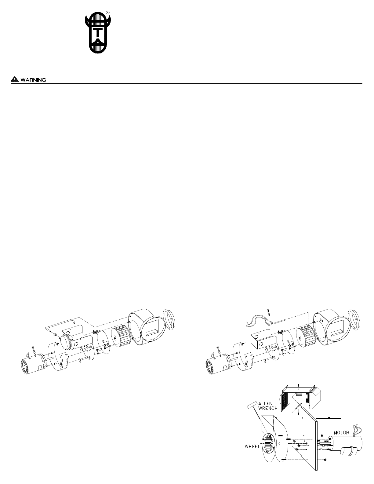
POWER VENTER MOTOR INSTALLATION
1. Check your Power Venter date code to determine whether it is an “old style” unit or “new style”.
A. FOR “NEW STYLE” (DATE CODE 12/88 UP TO PRESENT, SEE DIAGRAM A).
1. Loosen Fan Proving Tube nylon nut and carefully remove sensing tube from housing so as not to bend it.
2. Loosen Power Venter wheel set screw.
3. Remove motor from motor mount by removing 4 nuts which secure it. NOTE: USE CARE SO AS NOT TO LOSE SPACERS AND NUTS.
4. Position new motor so that studs extend into motor mount. Motor wires must match up with hole of junction box containing electrical shorty bushing.
Feed motor wires through bushing and into junction box. Shaft must be inserted through wheel hub.
5. Firmly fasten motor to motor mount (4 nuts) with a wrench. NOTE: BE SURE TO INCLUDE SPACERS BETWEEN MOTOR AND MOTOR MOUNT,
AS WELL AS APPROPRIATE FASTENERS.
6. Tighten wheel set screw on flat part of shaft.
7. Insert fan proving switch sensing tube into housing (short end) gently and secure to fan proving switch with nylon nut.
B. FOR “OLD STYLE” (DATE CODE PRIOR TO 12/88, SEE DIAGRAM B.)
1. Loosen Power Venter wheel set screw.
2. Remove motor from motor mount by removing 4 nuts which secure it. NOTE: USE CARE SO AS NOT TO LOSE SPACERS AND NUTS.
3. Position new motor so that studs extend into motor mount. Motor wires must match up with hole of junction box containing electrical shorty bushing.
Feed motor wires through bushing and into junction box. Shaft must be inserted through wheel hub.
4. Firmly fasten motor to motor mount (4 nuts) with a wrench. NOTE: BE SURE TO INCLUDE SPACERS BETWEEN MOTOR AND MOTOR MOUNT,
AS WELL AS APPROPRIATE FASTENERS.
5. Tighten wheel set screw on flat part of shaft.
2. Wire Power Venter motor according to appropriate model on the opposite side of this sheet. Be sure grounding wire from motor is utilized. UNIT MUST BE
GROUNDED! All wiring must be done in accordance with the NEC and applicable local codes. The wiring to the furnace should be protected by overcurrent
protection (fuses or circuit brakers) rated 15 amperes or less, as applicable of 14 AWG conductors. CAUTION MUST BE EXERCISED TO ENSURE THAT
WIRING DOES NOT COME INTO CONTACT WITH ANY HEAT SOURCE.
3. Before testing installation, on “old style” units check sail switch in Power Venter junction box. Sail must operate freely in slot of fan housing. Operation of
switch can be determined by hearing a “click” as switch opens and closes. A “click” must be heard before sail blade touches either end of slot. If “clicks” are
not heard, it may be necessary to change bend in blade slightly.
4. Check heater and Power Venter operation. Draft control on Power Venter should be adjusted so that there is no spillage at draft diverter, barometric or hood.
DIAGRAM A DIAGRAM B
IN-FORCERTMMODEL PAI-3 MOTOR INSTALLATION
1. Disconnect motor leads inside IN-FORCER.
2. Remove top and bottom screw which hold blower assembly plate in IN-FORCER.
3. Carefully slide out motor and housing assembly from IN-FORCER.
4. Loosen wheel set screw.
5. Remove (3) nuts which hold housing to blower assembly plate.
6. Remove (3) nuts which hold motor to blower assembly plate.
7. Install new motor in in reverse order. Make sure wheel is spaced evenly in housing
and set screw is tightened on flat of motor shaft.
8. Run IN-FORCER through heating cycle to verify proper operation.
DIAGRAM C
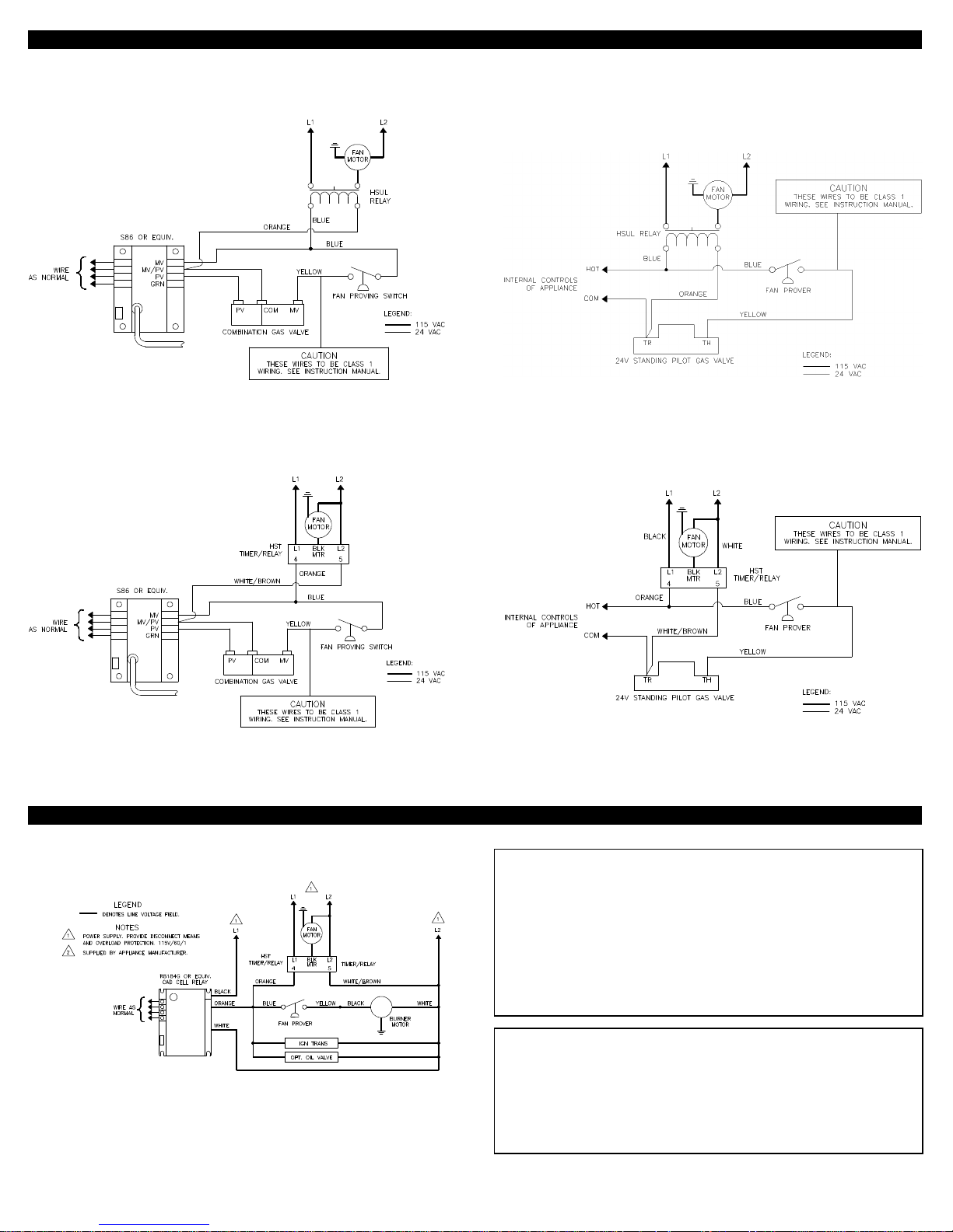
TYPICAL POWER VENTER GAS WIRING DIAGRAMS
REV. 2, 12/97
© 1997 TJERNLUND PRODUCTS, INC.
P/N 8504048
HSUL/GPAK CONNECTED TO 24V ELECTRONIC IGNITION
HSUL/GPAK CONNECTED TO 24V STANDING PILOT
HST/GPAK-T CONNECTED TO 24V ELECTRONIC IGNITION HST/GPAK-T CONNECTED TO 24V STANDING PILOT
NOTE: The WHITE/BROWN wire from terminal 5 of the Timer/Relay is
ORANGE in the GPAK-T Series. The ORANGE wire from
terminal 4 of the Timer/Relay is BLUE in the GPAK-T Series.
TYPICAL POWER VENTER OIL WIRING DIAGRAM
HST CONNECTED TO AN R8184G
BURNER MOTOR LESS THAN 3 AMPS @ 120 VAC
NOTE: The WHITE/BROWN wire from terminal 5 of the Timer/Relay is
ORANGE in the GPAK-T Series. The ORANGE wire from
terminal 4 of the Timer/Relay is BLUE in the GPAK-T Series.
SERVICE
Specific instructions cannot be made concerning frequency
of lubrication. Usually oiling every 3 months during the
heating season will be sufficient. NO MORE THAN 3
DROPS of SAE 20 oil should be used. Oil holes or lances
are provided at the front and rear faces of motor.
NOTE: Magnetek motors do not need to be oiled.
NOTE
IF YOUR ELECTRICAL DIAGRAM IS NOT INCLUDED,
CONTACT OUR CUSTOMER SERVICE DEPARTMENT
AT 1-800-255-4208, 7:30 TO 4:30 CST FOR FURTHER
ASSISTANCE.
 Loading...