

Page 1
TJERNLUND PRODUCTS, INC.
1601 Ninth Street • White Bear Lake, MN 55110-6794
PHONE (800) 255-4208 • (651) 426-2993 • FAX (651) 426-9547
Visit our web site • www.tjernlund.com
MODEL (950-0625) SS1 REPLACEMENT MOTOR WITH WHEEL KIT INSTRUCTIONS
Disconnect power supply before making wiring connections to prevent electrical shock and equipment damage.
IMPORTANT:
Motor replacement will depend on which of the three date code periods the SideShot was manufactured during. For SideShots with
date codes prior to “9226”, (black FASCO motor with 2 wire leads), design enhancements have made replacements of these motors
obsolete. It is necessary to replace the entire Plenum Section part # 950-0670 which includes the motor and electrical controls.
SideShots with date codes after “9518”, (gray MAGNETEK motor with 2 wire leads)
For the steps following below, refer to diagram A.
1. Remove electrical box cover and disconnect (2) motor leads.
2. Remove and save (1) motor bracket screw from electrical box.
3. Holding the motor, apply firm pressure towards the plenum of the SideShot and
remove and save the (6) motor mount nuts. Note: Hold the assembly firmly;
failure to do so could damage internal parts.
DIAGRAM A
4. Slide motor/wheel assembly from Plenum. Grasp only the motor casing;
do not damage wheel, shaft or other components on Plenum. Do not rest
assembly on wheel.
5. Install new motor/wheel assembly into Plenum with leads facing electrical box. Use caution when inserting motor/wheel
assembly into Plenum to avoid wheel damage. Firmly fasten motor to plenum using (6) nuts removed in step 3 above.
6. Route wires from motor into electrical box. Slip BLACK onto terminal “M” and WHITE onto terminal “L2” of terminal strip.
7. Reinstall (1) motor bracket screw removed from step 2 above.
8. Reestablish power and run SideShot through heating cycle to verify proper operation.
SideShots with a date code between “9226” and “9517”, (gray MAGNETEK motor with 3 wire leads)
For the steps following below, refer to diagram B.
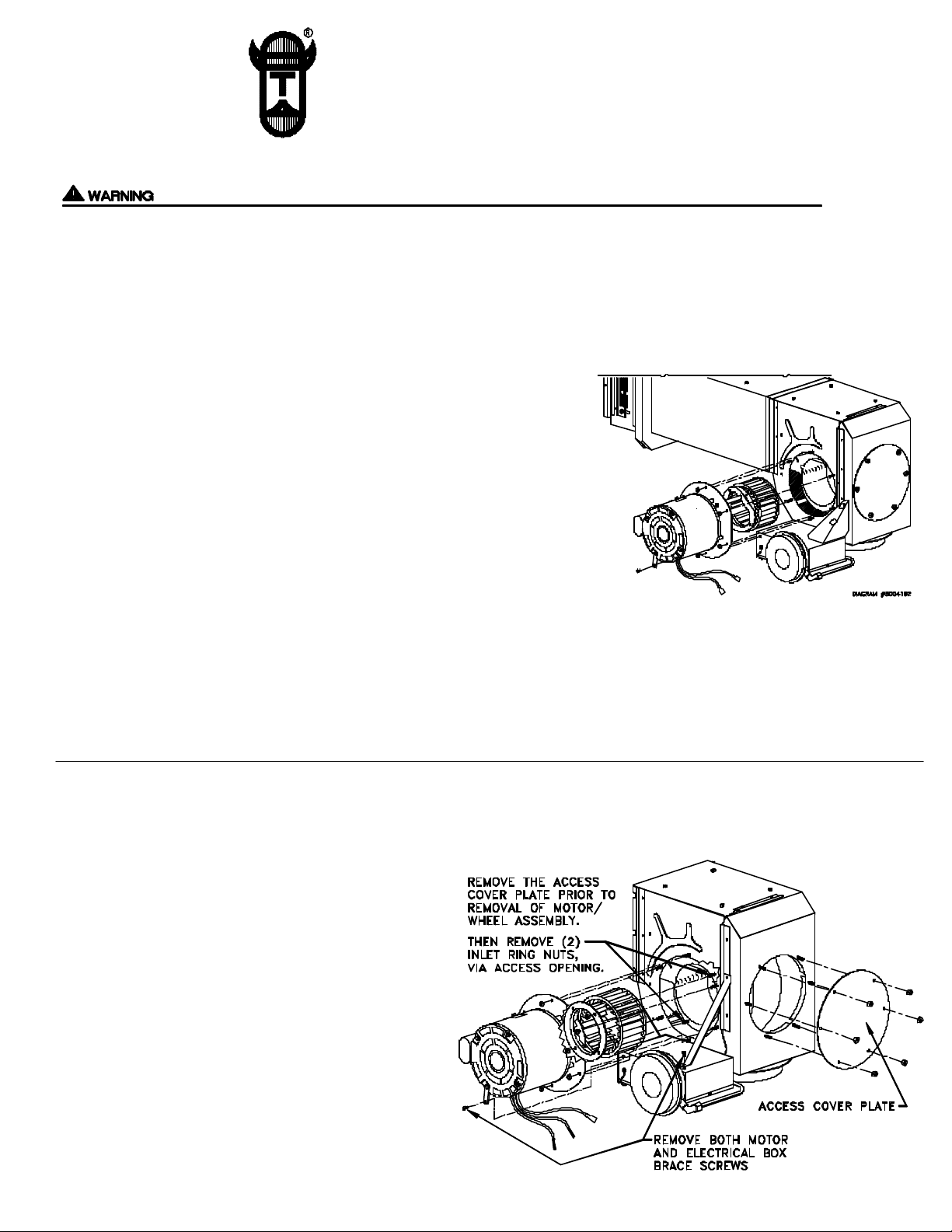
1. Remove electrical box cover and remove (3) motor leads.
2. Remove and save (2) motor & electrical box brace screws.
3. Remove and save (2) nuts from inlet collar on
housing inside plenum. Note: Removal of plenum
access cover plate will allow for removal of inlet
collar nuts with 11/32” box end wrench.
4. Push down electrical box about 1/4” so motor mount plate
can clear junction box. Once motor mount plate has
cleared the studs it can be rotated so motor mount plate flat
aligns up with junction box for easier removal.
DIAGRAM B
5. Holding the motor, apply firm pressure towards the
plenum of the SideShot and remove and save the (6)
motor mount nuts. Note: An 11/32” box end wrench
is used for nut directly under electrical box. Note:
Hold the assembly firmly; failure to do so could
damage internal parts.
Page 2
6. Slide motor/wheel assembly from Plenum. Grasp only the motor casing; do not damage wheel, shaft or other
components on Plenum. Do not rest assembly on wheel.
For the steps following below, refer to diagram C.
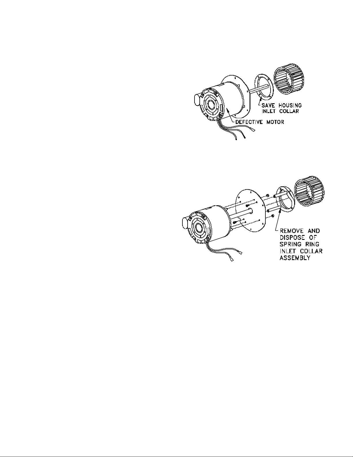
7. Loosen set screw from wheel hub with 5/32” allen wrench.
8. Twist wheel to loosen and pull off of motor shaft. Wheels
“fused” to shaft may require penetrating oil and/or a wheel
puller to facilitate removal. Discard old wheel when removed.
Important: The housing inlet collar from old motor will
have to be removed and saved for use with the new motor.
For the steps following below, refer to diagram D.
The new motor/wheel with spring ring inlet collar assembly is only compatible with SideShots with date codes after 9518. The following
modifications will have to be made to adapt the motor/wheel assembly to the SideShot with date codes between 9226 and 9517.
9. Loosen set screw with 5/32” allen wrench and remove
wheel from new motor.
10. Remove and save (4) nuts from the new motor mounting
plate and remove from motor. Leave spacers on motor
studs.
11. Remove (2) screws which hold spring ring inlet collar assembly to
mounting plate and discard spring ring inlet collar assembly.
DIAGRAM C
DIAGRAM D
12. Secure motor to mounting plate with (4) nuts removed in
step 10. Important: The capacitor of the motor should be
opposite the flat edge on motor mounting plate.
13. Place inlet collar removed in step 8 over new motor shaft so
embossed edge will be facing wheel cavity, (See Diagram C).
14. Place wheel on new motor shaft with wheel cavity facing motor and firmly tighten set screw on flat of shaft, (See Diagram C).
For the steps following below, refer to diagram B.
15. Install new motor/wheel assembly into Plenum with leads facing electrical box. Use caution when inserting motor/wheel
assembly into Plenum to avoid wheel damage. Firmly fasten motor to plenum using (6) nuts removed in step 5.
16. Line up inlet collar so housing studs go through the collar ring. Note: Inlet ring embossed edge should penetrate into blower
housing. Install and tighten the (2) nuts for the inlet collar which were removed in step 3.
17. Replace plenum access cover plate and tighten (6) nuts removed in step 3.
18. Reinstall motor and electrical box brace screws removed from step 2.
19. Route BLACK and WHITE wires from motor into electrical box . Note: A ground wire is not included on these
replacement motors. The motor is grounded by contact with the Plenum and ground wire from terminal strip to Plenum.
20. Remove 1/4” of insulation from the WHITE wire of motor and connect to “L2” of terminal strip. Connect BLACK motor
lead to “M” of Timer/Relay.
21. Reestablish power and run SideShot through heating cycle to verify proper operation.
P/N: 8504016 ©1999 TJERNLUND PRODUCTS, INC. ALL RIGHTS RESERVED REV. A 11/99
 Loading...