

TJERNLUND 950-0020 115V COOLING FAN 8504073 REV. A 0906, 950-0020, SIDESHOT SS2 User Manual
(950-0020) 115 VAC FAN REPLACEMENT INSTRUCTIONS
FOR SS2 SIDESHOT® VENT SYSTEMS SEE INSTRUCTIONS BELOW
Disconnect power supply before servicing SS2 to prevent electrical shock and equipment damage.
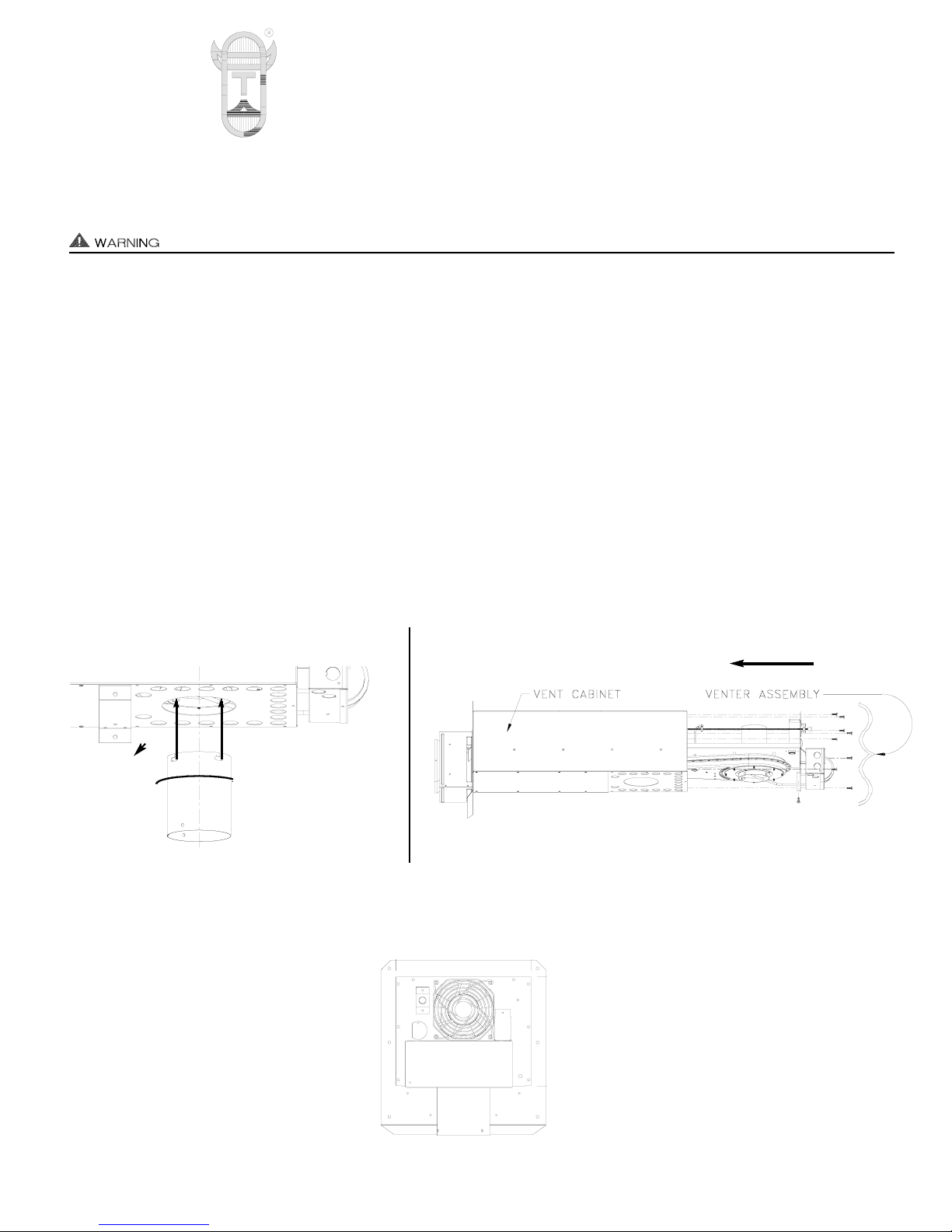
1. Disconnect flue pipe from inlet collar of SS2.
2. Remove SS2 inlet pipe by twisting counterclockwise, (See Diagram A).
3. Remove (9) screws from rear and bottom of vent cabinet. Slide venter assembly out of vent cabinet and lay on its side on a flat
working surface, (See Diagram B).
4. Remove the BLACK and WHITE wires connected to the cooling fan.
5. Remove the (4) nuts holding the cooling fan guard and cooling fan to the venter assembly, (See Diagram C).
6. IMPORTANT: Make sure Cooling Fan air flow arrow is directed to inside of Venter, (See Diagram B). Insert (4) 8-32 x 1/2” studs
through fan flange, SS2 Venter Assembly and fan guard. Tighten (4) nuts to secure fan guard and fan to Venter Assembly.
7. Follow steps 4 - 1 in reverse order for reassembly.
8. Run SS2 & equipment through a couple of heating cycles to verify proper operation.
Rev. A 09/06 Copyright © 2006, Tjernlund Products, Inc. All rights reserved. P/N 8504073
DIAGRAM B
DIAGRAM A
DIAGRAM C
TJERNLUND PRODUCTS, INC.
1601 Ninth Street • White Bear Lake, MN 55110-6794
PHONE (800) 255-4208 • (651) 426-2993 • FAX (651) 426-9547
Visit our web site • www.tjernlund.com
Important:
Cooling Fan
air flow direction
FOR CRAWL SPACE VENTILATORS SEE INSTRUCTIONS BELOW
Disconnect power or unplug 115 VAC power cord before servicing the crawl space ventilator.
1. Remove Crawl Space Ventilator from wall. Important: Note setting of dehumidistat (if equipped) so it can be reset when finished.
Remove BLACK and WHITE motor leads from defective cooling fan.
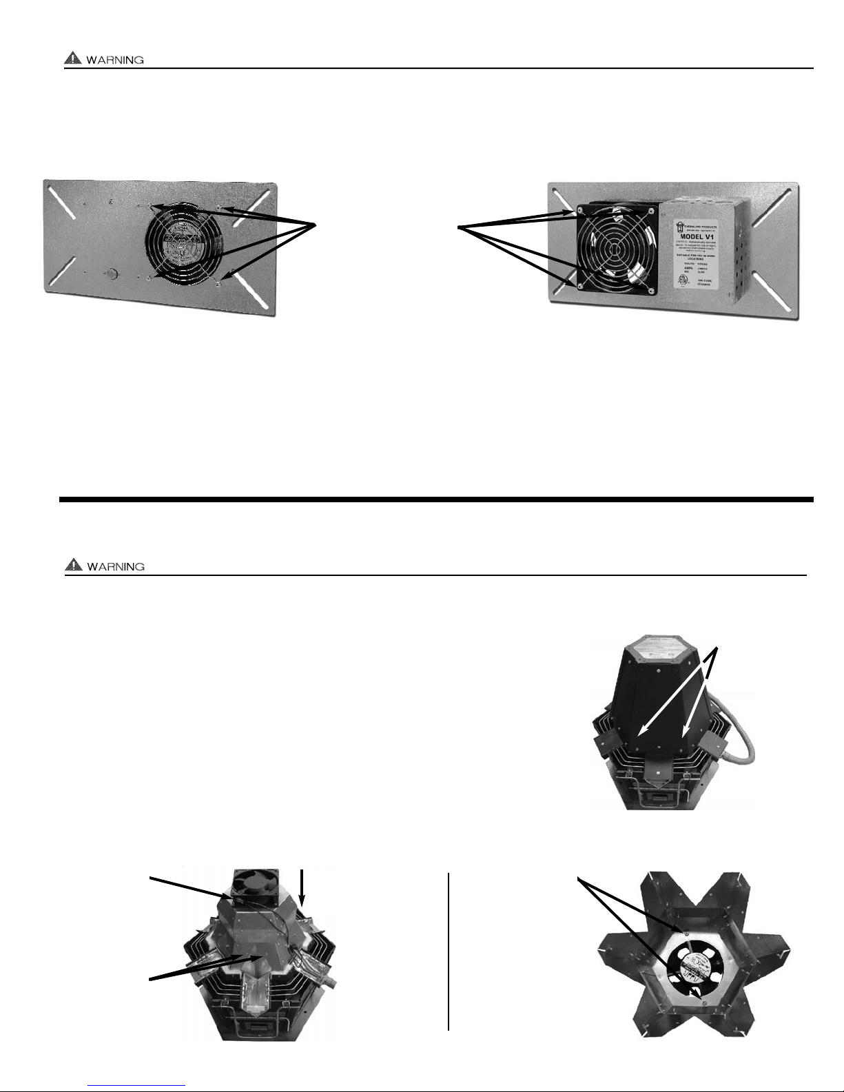
2. Use caution and drill out (4) rivets from exterior and interior guard of defective fan with a 5/32” drill bit, (See Diagram D).
3. IMPORTANT: Make sure air flow arrow is directed to the exterior side of mounting plate so air flows from the crawl space to
outdoors. Insert (4) 8-32 x 1/2” studs through fan flange, mounting plate and exterior fan guard. Tighten (4) keps nuts to secure fan
guard and fan to mounting plate. Insert (4) 8-32 x 1/2” studs through fan flange and tighten (4) keps nuts to secure interior fan guard on fan.
4. Replace BLACK and WHITE motor leads and reinstall Crawl Space Ventilator in opening.
5. Reestablish 115 VAC power and cycle Crawl Space Ventilator “on” to verify proper operation. Reset dehumidistat (if equipped).
NOTE: If outside temperature is below 50
o
F, T-stat may not allow Ventilator to turn on.
FOR AUTO-DRAFT® INDUCERS WITH 115 VAC COOLING FANS SEE INSTRUCTIONS BELOW
Remove any appliance calls for heat and disconnect power to Auto-Draft® Inducer and appliances before servicing.
1. Remove (2) screws from each Auto-Draft exterior housing side (12 total), (See Diagram E).
2. Remove Cooling Fan motor leads and (2) Screws from Auto-Draft motor cowling side
(12 total), (See Diagram F).
4. Remove (2) nuts securing defective Cooling Fan to motor cowling, (See Diagram G).
IMPORTANT: Verify defective Cooling Fan motor you are replacing is 115 VAC.
5. IMPORTANT: Make sure air flow arrow is directed to blow air down into motor cowling,
(See Diagram F). Reinstall new 115 VAC Cooling Fan using (2) 8-32 x 1/2” studs and
tighten (2) nuts, (See Diagram G).
6. Follow Steps 2 & 1 in reverse order for reassembly. Reestablish power to Inducer and
appliances. Run Inducer through a couple of heating cycles to verify proper operation.
DIAGRAM E
DIAGRAM F
DIAGRAM G
DIAGRAM D
EXTERIOR VIEW
INTERIOR VIEW
Remove (2)
screws from
each Auto-Draft
housing side
Remove (2) nuts
which secure
Cooling Fan to
motor cowling
Remove
Cooling Fan
motor leads
Remove (2)
screws from
each Auto-Draft
motor cowling
side
Model V1 Shown
Drill out (4) rivets on
interior and exterior fan
housing with 5/32” drill
bit.
Important:
Cooling Fan
air flow direction
 Loading...