

Page 1
Copyright © 2011, Tjernlund Products, Inc. All rights reserved. P/N 8504067
REV. A 11/11
READ INSTRUCTIONS CAREFULLY
RELAY/TIMER PART NUMBER 950-0014
NON-ADJUSTABLE RELAY/TIMER
OWNERS INSTRUCTIONS
THESE INSTRUCTIONS MUST REMAIN
WITH EQUIPMENT
DO NOT DESTROY
ALWAYS FOLLOW HEATER
MANUFACTURER’S INSTRUCTION
FOR PROPER OPERATION OF
HEATER AND RELIGHTING OF PILOT
PART #950-0014 INSTALLATION INSTRUCTIONS
24-120 VAC INPUT APPROX. 45 SECOND ( + 10% )
NON-ADJUSTABLE POST-PURGE RELAY/TIMER
A) Disconnect 120 VAC Power from the Power Venter before continuing.
B) All wiring from the Power Venter to the appliance must be appropriate class 1 wiring as follows: installed in rigid-metal conduit,
intermediate metal conduit, rigid non-metallic conduit, electrical metallic tubing, Type MI Cable, Type MC Cable or be otherwise
suitably protected from physical damage.
120 VAC SUPPLY AND OUTPUT TO MOTOR WIRING
The output or motor switching side of the #950-0014 has three terminals. L1 or
the 120 VAC supply power lead is attached to terminal 2. White or the 120 VAC
neutral/return lead is attached to terminal 3 and the Black or 120 VAC “hot” motor
lead is attached to terminal 1. IMPORTANT: Terminals 2 (L1) and 3 (L2) must be
powered continuously with 120 VAC.
ELECTRICAL RATING
The Terminal 1 (Motor Load) and Terminal 3 (L2) 120 VAC Load contacts are
rated for 1/4 H.P. @ 120 VAC.
REPLACEMENT OF DEFECTIVE RELAY/TIMER
1. Remove the electrical box cover of the Power Venter.
2. Mark the Black wire on defective Timer which is the load wire to the motor. This terminal will be marked BLK MOTOR, LOAD or be
the #1 Terminal if replacing an Airotronics Timer. Remove the defective Timer and (4) plastic stand offs if necessary.
3. Place the 120 VAC supply L1 Black wire on Terminal 2. Place the White L2 wire on Terminal 3 and place the Black Motor Load wire
on Terminal 1, (See Diagram A).
NOTE: When the 120 VAC Supply power is first established to the Relay/Timer, it may automatically reset into post purge. After the
venter operates for approximately 45 seconds it will shut off and be ready for normal operation.
TJERNLUND PRODUCTS, INC.
1601 Ninth Street • White Bear Lake, MN 55110-6794
PHONE (800) 255-4208 • (651) 426-2993 • FAX (651) 426-9547
Visit our web site • ww w.tjernlund.com
1
3
2
5
4
MOTOR (BLACK)
L1 (BLACK)
(WHITE)
L2
LOAD
50/60 HZ
120 VAC
DIAGRAM A
1/4 H.P. @ 120 VAC
Page 2
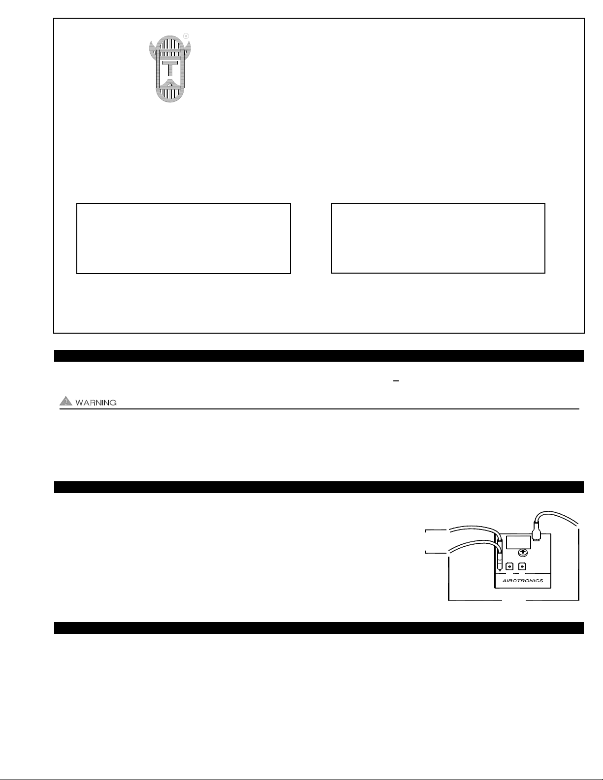
If you are replacing the Relay/Timer of a VP-2 or VP-3, connect the control
input voltage as shown in Diagram B.
CONTROL INPUT
BLUE
ORANGE
1
3
2
5
4
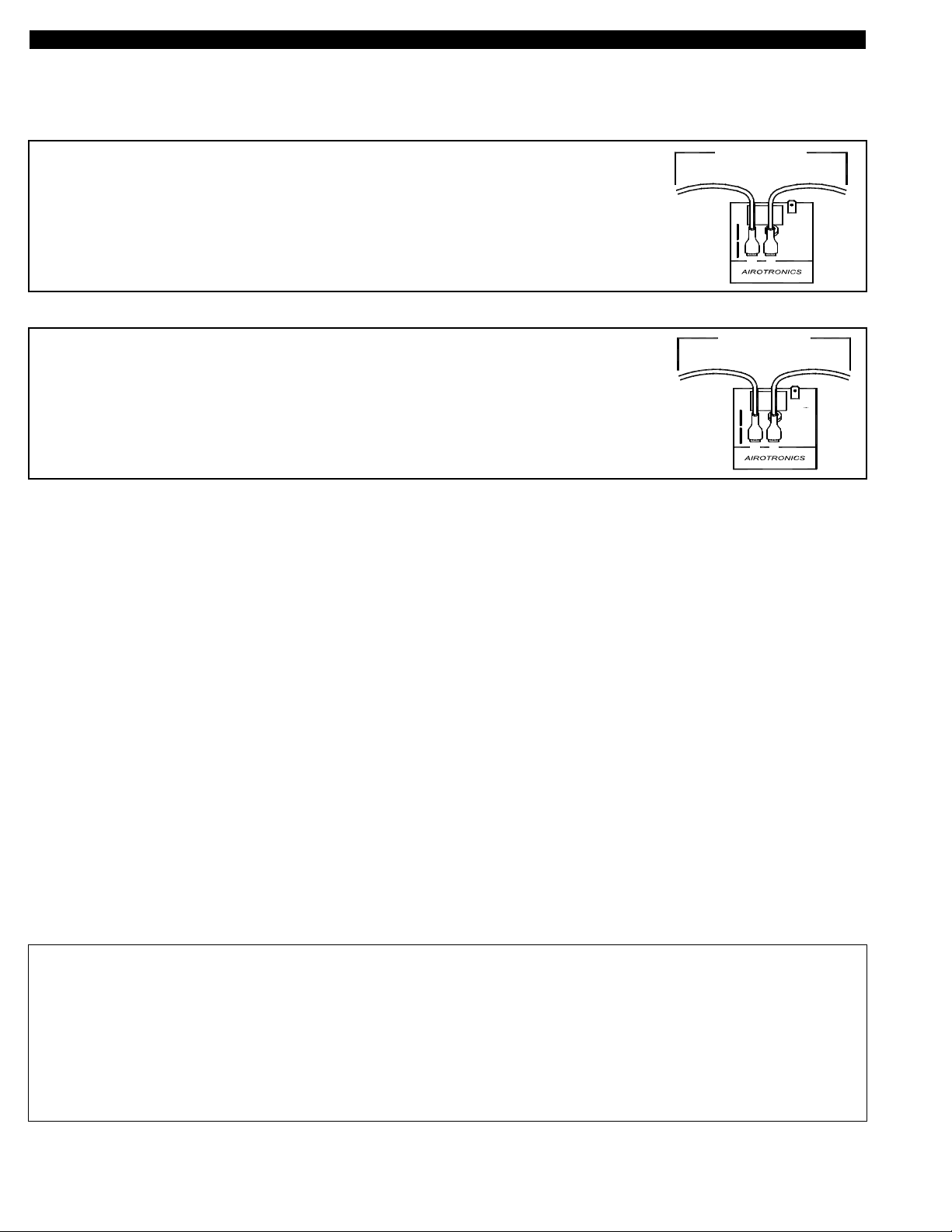
4
5
2
3
1
YELLOW
BLUE
CONTROL INPUT
If you are replacing the Relay/Timer of any GPAK-JT/GPAK-1T/GPAK-1TR
connect the control input voltage as shown in Diagram C.
Secure Timer to the inside of the electrical box using the nut & screw provided. NOTE: When the 120 VAC Supply power is first
established to the Relay/Timer, it may automatically reset into post purge. After the venter operates for approximately 45 seconds it
will shut off and be ready for normal operation.
After new Relay/Timer is installed, run appliance and power vent system through a couple of heating cycles to verify proper operation.
If you have any questions regarding installation, please contact our Customer Service Department by calling: 1-800-255-4208,
Monday-Friday, 7:30-4:30 CST.
TJERNLUND LIMITED 1 YEAR WARRANTY
Tjernlund Products, Inc. warrants to the original purchaser of this product that the product will be free from defects due to faulty material or workmanship for a period of (1)
year from the date of original purchase or delivery to the original purchaser, whichever is earlier. Remedies under this warranty are limited to repairing or replacing, at our
option, any product which shall, within the above stated warranty period, be returned to Tjernlund Products, Inc. at the address listed below, postage prepaid. THERE ARE
NO WARRANTIES WHICH EXTEND BEYOND THE DESCRIPTION ON THE FACE HEREOF, AND TJERNLUND PRODUCTS, INC. EXPRESSLYDISCLAIMS LIABILITY
FOR INCIDENTALOR CONSEQUENTIAL DAMAGES ARISING FROM THE USE OF THIS PRODUCT. THIS WARRANTY IS IN LIEU OF ALL OTHER EXPRESS WARRANTIES AND NO AGENTIS AUTHORIZED TO ASSUME FOR US ANY LIABILITY ADDITIONAL TO THOSE SET FORTH IN THIS LIMITED WARRANTY . IMPLIED W ARRANTIES ARE LIMITED TO THE STATED DURATION OF THIS LIMITED WARRANTY. Some states do not allow limitation on how long an implied warranty lasts, so that
limitation may not apply to you. In addition, some states do not allow the exclusion or limitation of incidental or consequential damages, so that above limitation or exclusion may not apply to you. This warranty gives you specific legal rights and you may also have other rights which may vary from state to state. Send all inquiries regarding warranty work to Tjernlund Products, Inc. 1601 9th Street, White Bear Lake, MN 55110-6794. Phone (651) 426-2993 • (800) 255-4208 • Fax (651) 426-9547 • Email
fanmail@tjfans.com.
DIAGRAM B
DIAGRAM C
CONTROL INPUT WIRING
The #950-0014 is designed to accept 24-120 VAC control input signals.
 Loading...