

TJEP LB-18 T-NUT Operation And Maintenance Manual
- 1 -
1
OPERATION and MAINTENANCE MANUAL
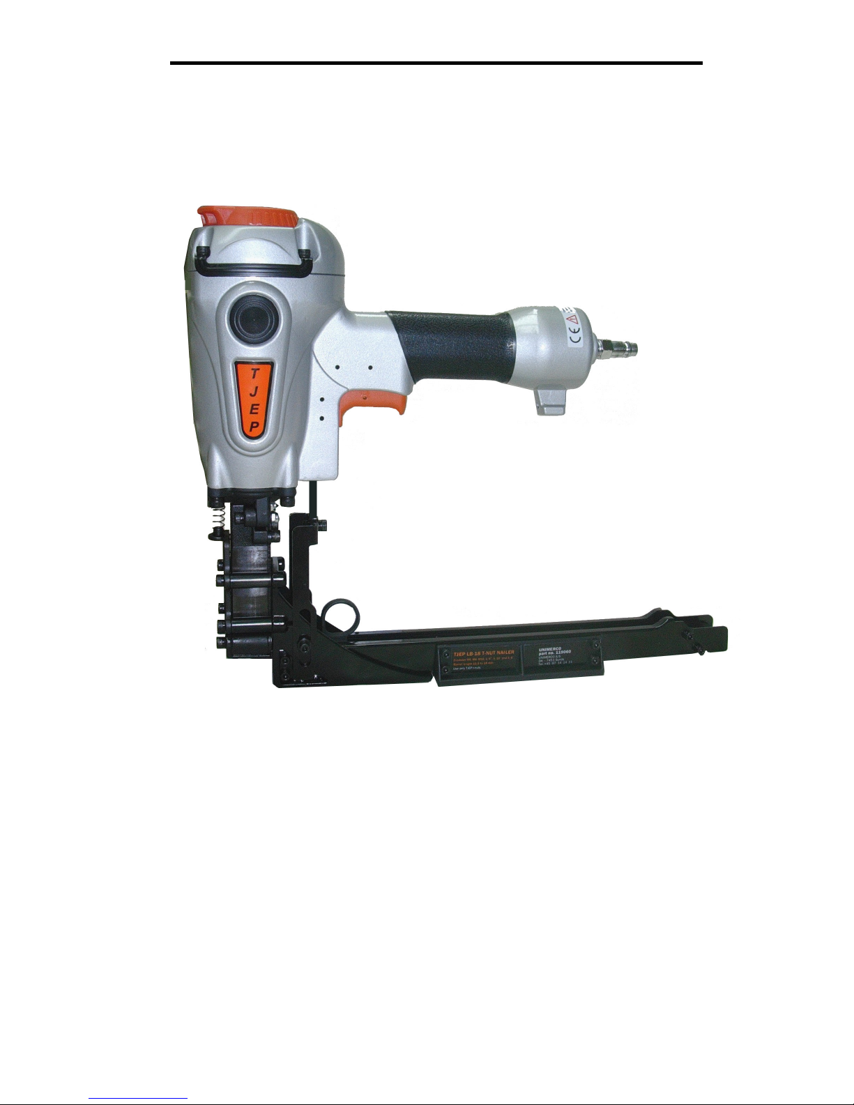
MODEL : TJEP LB-18 T-NUT
NAILER
DRIVES 11,5-18MM (7/16”-3/4”) T-NUTS
,!
WARNING:
BEFORE OPERATING THIS TOOL, ALL OPERATORS SHOULD STUDY MANUAL
TO UNDERSTAND AND FOLLOW THE SAFETY WARNINGS AND INSTRUCTIONS.
KEEP THESE INSTRUCTIONS WITH THE TOOL FOR FUTURE REFERENCE. IF
YOU HAVE QUESTIONS, CONTACT YOUR DISTRIBUTOR.
- 2 -
2
INTRODUCTION
The pneumatic tools is a precision-built tool, designed for high speed, high volume
fastening. These tools will deliver efficient, dependable service when used correctly, and
with care. As with any fine power tool for best performance the manufacture’s
instructions must be followed. Please study this manual before operating the tool and
understand the safety warning and cautions. The instructions on installation, operation
and maintenance should be read, carefully, and the manual kept for reference. NOTE:
Additional safety measures may be required because of your particular application of
the tool. Contact your representative or distributor with any questions concerning the
tool and its use.
INDEX
INTRODUCTION…………………………..……………………………………………….….1
SAFETY INSTRUCTIONS………………………………………………………………….…2
AIR SYSTEMS……………………………………………………………………………….…5
TOOL INSTALLATION……………………………………………………………………..…7
TOOL LOADING….……………………………………………………………………………8
TOOL OPERATION…………………………………………………………………………….9
MAINTENANCE…………………………………………………………………………….….10
OPERATOR TROUBLESHOOTING…………………………………………………………14
TOOL SPECIFICATIONS
MODEL LENGTH WIDTH HEIGHT WEIGHT CAPACITY
TJEP LB-18
322 mm
(12 11/16“)
403mm
(15 7/8“)
81mm
(3 3/16“)
3.2kg
(7,1lbs)
13 T-NUTS
FASTENER SPECIFICATIONS:
MODEL T-NUT SIZE DIAMETER BARREL LENGTH
TJEP LB-18
23×21mm
(7/8”
×13/16”)
M6, M8, M10
(1/4”, 5/16”, 3/8”)
11,5-18mm
(7/16”-3/4”)
TOOL AIR FITTING
This tool uses a 1/4” N.P.T male plug. The inside diameter should be .200”(5mm) or larger.
The fitting must be capable of discharging tool air pressure when disconnected from the
air supply.
OPERATING PRESSURE
70 to 110 p.s.i. (4,9 to 7,8kg/
2
) Select the operating pressure within this range for best
fastener performance.
DO NOT EXCEED THIS RECOMMENDED OPERATING PRESSURE.
NOISE CHARACTERISTIC VALUES IN ACCORDANCE WIT Enxxl:
A-weighted single-event sound pressure level at operator’s :LPA,2s= 89 dBA
A-weighted single-event sound power lever :LWA,1s= 98 dBA
A-weighted single-event surface sound pressure level :LPA,1s,1m= 85 dBA
VIBRATION CHARACTERISTIC VALUES IN ACCORDANCE WITH ISO 8662;
PART11:
Weighted root mean square acceleration: 3,01 m/s
2

- 3 -
3
SAFETY INSTRUCTIONS
SAFETY FIRST
These safety instructions provide information necessary for safe
operation of pneumatic tools. DO NOT attempt to operate the tool until
you read and understand all safety precautions and manual instructions.
WEAR EYE AND HEARING PROTECTION
Always wear hearing and eye protection devices, including side
shields when operating or working in the vicinity of a tool.
THE TOOL MUST BE USED ONLY FOR THE PURPOSE
FOR WHICH IT WAS DESIGNED
Do not throw the tool on the floor; strike the housing in any way or
the tool as a hammer to knock material into place.
NEVER ENGAGE IN HORSEPLAY WITH THE TOOL
The tool is not a toy so do not use it like one. Never engage in
horseplay with the tool or point it at yourself or any person, even if
you think it is not loaded.
NEVER ASSUME THE TOOL IS EMPTY
Check the magazine for fasteners that may be left in the tool. Even if
you think the tool is empty or disconnected never point it at anyone
or yourself. Unseen fasteners could fire the tool.
NEVER CLAMP THE TRIGGER IN A LOCKED OR
OPERATING POSITION
The trigger of the tool must never be tampered with; disabled or
clamped in a locked or operating position since this will cause the
tool to driver a fastener any time the work contacting element is
depressed.
DO NOT LOAD FASETNERS WITH THE AIR LINE
CONNECTED, OR WITH THE TOOL TRIGGER OR
WORK CONTACTING ELEMENT DEPRESSED
When loading fasteners into the tool, make sure to disconnect the air
line and not to depress the trigger or work contacting element.

- 4 -
4
SAFETY INSTRUCTIONS
OPERATE THE TOOL ONLY ON A WORKPIECE
The tool should be operated only when it is in contact with the work
piece. Even then you should be careful when fastening thin material
or working near the edges and corners of the work piece since the
fasteners may drive through or away from the work piece.
DO NOT DISABLE OR REMOVE THE WORK
CONTACTING ELEMENT
This tool is equipped with a safety mechanism, called a work
contacting element, to help prevent accidental firing. Never tamper
with, disable or remove the work contacting element. Do not use the
tool unless the work contacting element is working properly. The
tool could fire unexpectedly.
DISCONNECT THE TOOL WHEN NOT IN USE
Always disconnect the tool from the air line when it is not used or
when you leave the work area. The tool should never be left
unattended because people who are not familiar with the tool might
handle it and injure themselves or others.
CARRY THE TOOL ONLY BY THE HANDLE
Always carry the tool by the handle only. Never carry the tool by the
air hose or with the trigger depressed since you could drive a
fastener unintentionally and injure yourself or someone else.
DO NOT WEAKEN THE TOOL HOUSING
The tool housing is a pressure vessel and should never be weakened
by having your company’s name, area of work or anything else
stamped or engraved into its surface.
DISCONNECT THE TOOL WHEN PERFORMING
REPAIRS AND CLEARING JAMS
Never attempt to clear a jam or repair a tool unless you have
disconnected the tool from the air line and removed all remaining
fasteners from the tool.

- 5 -
5
SAFETY INSTRUCTIONS
ALWAYS USE THE PROPER FITTING FOR THE TOOL
Only MALE pneumatic type air connectors should be fitted to the
tool, so that high pressure air in the tool is vented to atmosphere as
soon as the air line is disconnected.
NEVER install FEMALE quick disconnect couplings on the tool.
Female couplings will trap high pressure air in the tool when the air
line is disconnected, leaving the tool charged and able to drive at
least one fastener.
DO NOT EXCEED THE MAXIMUM RECOMMENDED
AIR PRESSURE
Operate the tool only at the recommended air pressure. Do not
exceed the maximum air pressure marked on the tool. Be sure the
air pressure gauge is operating properly and check it at least twice a
day.
Never use any bottled air or gases such as oxygen to operate the tool
since they could cause the tool to explode.
KEEP THE TOOL CLEAN AND LUBRICATED
Clean the tool at least daily and lubricate as required. Never operate
a dirty or malfunctioning tool.
USE ONLY RECOMMENDED PARTS AND FASTENERS
Use only parts and fasteners specifically designed and recommended
for use in the tool and for the work to be done. Using unauthorized
parts and fasteners or modifying the tool in any way creates
dangerous situations. Replace all missing parts-refer to tool
schematic for correct placement and part number.
,! DANGER
,!
Failure to follow any of the above instructions could result
in severe personal injury to tool user and bystanders or cause
damage to tool and property.

- 6 -
6
AIR SYSTEMS
For air-powered tools to work their best, the air supply system must be
properly installed and maintained regularly. A drawing in this section
shows a properly installed air supply system. Handy checklists for
installing and maintaining air supply systems follow.
INDOOR AIR SYSTEM INSTALLATION BE CERTAIN
THAT:
All pipes supplying air have a large enough inside diameter to
ensure adequate air supply.
The main supply pipe slopes down, away from the compressor
(1/16 inch per foot).
Air storage is provided along lengthy air lines.
Pipe line branch outlets are at the top of the main pipe line.
Cut-off valves are provided at each branch pipe line throughout
the system.
Water legs extend from the bottom of each branch line.
A refrigerant-type dryer is installed on the system.
Air hoses are kept as short as practical.
A regular maintenance program is followed.
QUTDOOR AIR SYSTEM INSTALLATION BE CERTAIN
THAT:
A moisture trap and a filter/regulator/lubricator are installed at
the compressor.
Air hoses and fittings are large enough so that air flow not
restricted. Minimum hose size is 3/8 inch ID, with 1/2 inch ID hose
used for any application over 25 feet.
Air hoses are not longer than 150 feet.
 Loading...