

Page 1
Save This Manual for Future Reference
Original Instruction
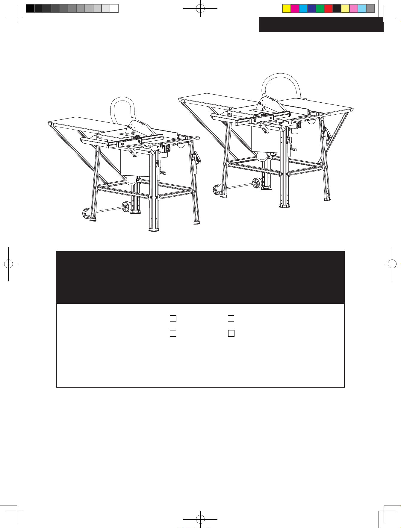
Table Saw
Operator’s Manual
MODEL NUMBER : 65062 65063
65066 65067
SERIAL NUMBER :
Both model number and serial number may be found on the main
label. You should record both of them in a safe place for future use.
FOR YOUR SAFETY
READ AND UNDERSTAND THE ENTIRE MANUAL BEFORE
OPERATING MACHINE
65063UK00M100.indd 1 2020/5/27 9:38:40
Page 2
GB
TABLE OF CONTENTS
INTRODUCTION
Introduction 2
Specifications 2
Symbols 3
Safety 3
Specific Safety Rules 4
Application Conditions 7
Electrical Requirements 7
Contents Supplied 8
Assembly 9
Know your Machine 13
Features & Controls 13
Set Up 14
Operation 16
Transport 17
Maintenance 17
Storage 19
Wiring Diagram 19
Trouble Shooting 20
Parts Schedule 21
Parts List 22
Your new Table saw will more than satisfy your
expectations. It has been manufactured under
stringent quality standards to meet superior
performance criteria. You will find it easy and
safe to operate, and with proper care, it will
give you many years of dependable service.
Carefully read through this entire
operator’s manual before using your
new Table saw. Take special care to
heed the cautions and warnings.
APPLICATION CONDITIONS
This table saw is designed for operating under
ambient temperatures between +5°C and
40°C and for installation at altitudes no more
than 1000m above M.S.L. The surrounding
humidity should less than 50% at 40°C. It
can be stored or transported under ambient
temperatures between -25°C and 55°C.
Specifications
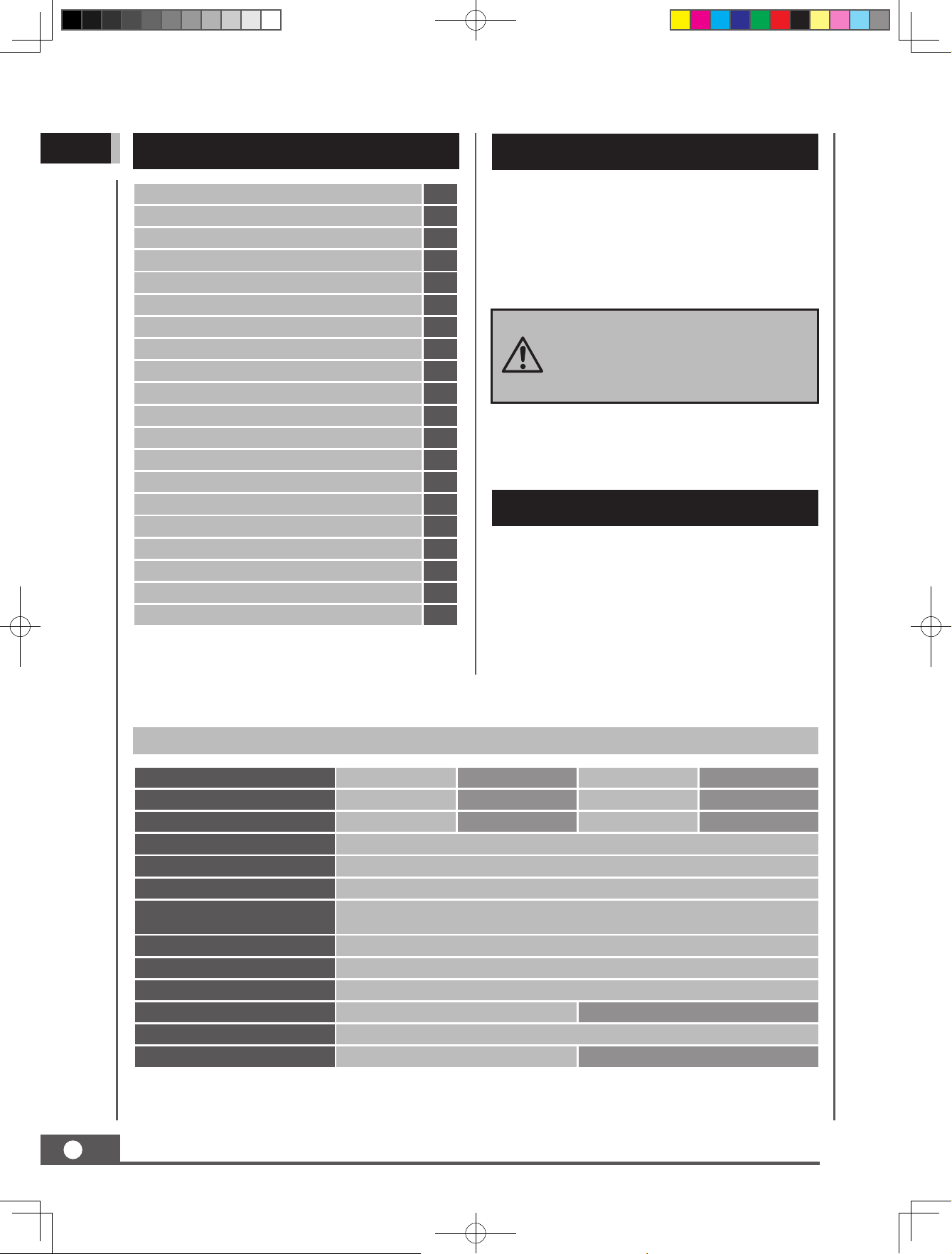
Model Number 65062 65063 65066 65067
AC Motor 400V 3~ 50Hz 230-240V~ 50Hz 400V 3~ 50Hz 230-240V~ 50Hz
Power P
Protection Category IP 54
Blade Size Ø 315 × Ø30 × 3.6 mm
Number of Saw Teeth 24
Cutting Capacity
Blade Tilt Adjustment 0°- 45°
Blade Speed 2950 /min
Standard Tabel Size 800×550 mm
Table Size with Extensions 1600×550 mm 1600×950 mm
Table Height 851 mm
Weight 50 kg 54.5 kg
2
TABLE SAW
(S6 40 % 5 min.)*
3000W 2200W 3000W 2200W
83 mm @ 0°
58 mm @ 45°
65063UK00M100.indd 2 2020/5/27 9:38:40
Page 3
Sound emission level (LpA)
Sound pressure level (LpA)
Sound power level (LwA)
* S6 40%, 5 min, continuous operation periodic
duty: time of one load cycle is 5 minutes,
operation time at constant load is 2 minutes,
operation time at no-load is 3 minutes.
94.9 db(A)
89.9 db(A)
103.9 db(A)
k=3 db(A)
k=3 db(A)
k=3 db(A)
RECYCLING AND DISPOSAL
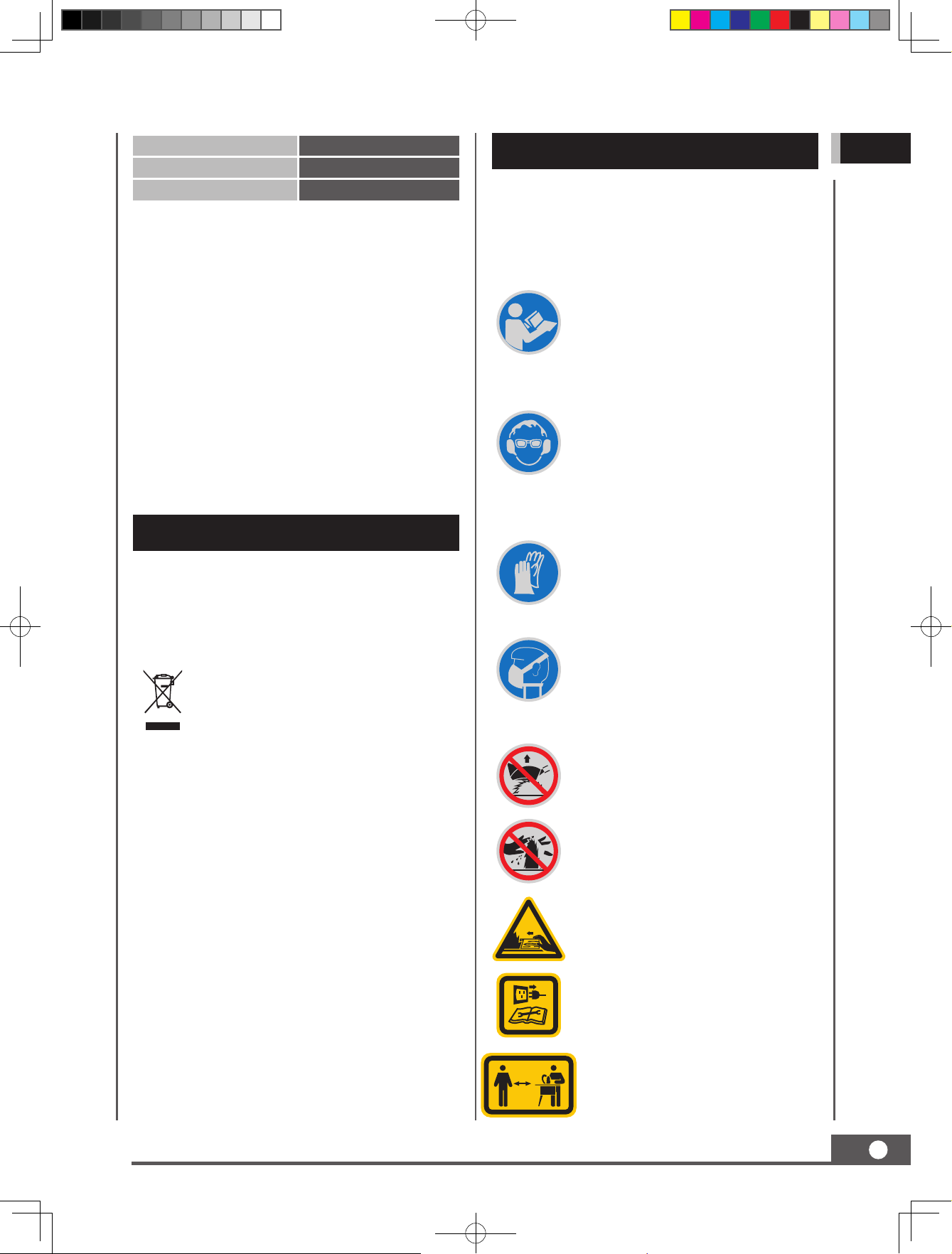
SYMBOLS
The rating plate on your machine may
show symbols. These represent important
information about the product or instructions
on its use.
Read these instructions for use
carefully.
Caution! Wear ear-muffs. The
impact of noise can cause damage
to hearing.
Caution! Wear safety goggles.
Sparks generated during working
or splinters, chips and dust
emitted by the device can cause
loss of sight.
GB
This marking indicates that this
product should not be disposed with
other household wastes. To prevent
possible harm to the environment
or human health from uncontrolled
waste disposal, recycle it responsibly
to promote the sustainable reuse of
material resources. To return your
used device, please use the return
and collection systems or check with
your local authority or local stores
for advice of environmental safe
recycling.
Wear protective gloves.
Caution! Wear a breathing mask.
Dust which is injurious to health
can be generated when working
on wood and other materials.
Never use the device to work on
any materials containing asbestos!
It is forbidden to remove or
tamper with the protection
devices and safety devices.
Caution! Risk of injury! Failure
to keep your hands away from
the blade will result in serious
personal injury.
Disconnect the mains plug prior
to the repair, cleaning, and
maintenance of the splitter!
Keep children and bystanders off
and away.
TABLE SAW
65063UK00M100.indd 3 2020/5/27 9:38:41
3
Page 4
GB
SAFETY
General Safety Rules
Understand your Machine
Read this manual and labels affixed to the
machine to understand its limitations and
potential hazards.
Be thoroughly familiar with the controls and
their proper operation. Know how to stop the
machine and disengage the controls quickly.
Do not attempt to operate the machine until
you fully understand how to properly operate
and maintain the engine and how to avoid
accidental injuries and/or property damage.
If the unit is to be used by someone other than
original purchaser or loaned, rented, or sold,
always provide this manual and any needed
safety training before operation. The user can
prevent and is responsible for accidents or
injuries that may occur to themselves, other
people, and property.
Do not force the machine. Use the correct
machine for your application. The correct
machine will do the job more efficiently and
safer at the rate it was designed.
Personal Safety
Do not permit children to operate this machine
at any time.
Keep children, pets, and other people not
using the unit away from the work area. Be
alert and shut off unit if anyone enters work
area. Keep children under the watchful care of
a responsible adult.
Do not operate the machine while under the
influence of drugs, alcohol, or any medication
that could affect your ability to use it properly.
Wear appropriate hearing protection. Wear
respiratory protection to avoid the risk of
inhaling harmful dust.
Always keep hands and feet away from all
moving parts during operation. Moving parts
can cut or crush body parts.
Always keep hands and feet away from all
pinch points.
Do not touch parts that might be hot
from operation. Allow parts to cool before
attempting to maintain, adjust, or service.
Stay alert, watch what you are doing, and use
common sense when operating the machine.
Do not overreach. Do not operate the machine
while barefoot or when wearing sandals or
similar lightweight footwear. Wear protective
footwear that will protect your feet and
improve your footing on slippery surfaces.
Keep proper footing and balance at all times.
This enables better control of the machine in
unexpected situations.
Inspect your Machine
Check your machine before starting it. Keep
guards in place and in working order. Make
sure all nuts, bolts, etc., are securely tightened.
Never operate the machine when it is in need
of repair or is in poor mechanical condition.
Replace damaged, missing, or failed parts
before using it. Keep the machine in safe
working condition. Regularly check to see that
keys and adjusting wrenches are removed
from the machine area before starting it. A
wrench or a key that is left attached to a
rotating part of the machine may result in
personal injury. Avoid accidental starting.
Be sure the motor switch is off before
transporting the machine or performing any
maintenance or service on the unit.
Dress properly. Wear heavy long pants, boots,
and gloves. Do not wear loose clothing, short
pants, or jewelry of any kind. Secure long hair
so it is above shoulder level. Keep your hair,
clothing, and gloves away from moving parts.
Loose clothes, jewelry, or long hair can be
caught in moving parts.
Protect eyes, face, and head from objects that
may be thrown from the unit. Always wear
safety goggles or safety glasses with side
shields when operating.
4
65063UK00M100.indd 4 2020/5/27 9:38:41
TABLE SAW
Transporting or performing maintenance
or service on a machine with its switch on
invites accidents. If the machine should start
to vibrate abnormally, stop the motor and
check immediately for the cause. Vibration is
generally a warning sign of trouble.
Electric Safety
Avoid use of free and inadequately insulated
connections. Connections must be made with
protected material suitable for outdoor use.
Page 5
Protect yourself from electric shock. Do not
plug or unplug the motor while standing in or
around damp or wet ground. Do not use the
unit in wet or damp areas or expose it to rain.
Prevent body contact with grounded surfaces:
pipes, radiators, ranges, and refrigerator
enclosures. Make sure your fingers do not
touch the plug’s metal prongs when plugging
or unplugging the unit.
Avoid inadvertent starting. Make sure that the
switch is switched off when plugging the plug
into an outlet.
Only use approved and appropriately
identified extension cables for use outdoors.
Only use cable reels in the unrolled state.
Do not use the cable for purposes for which
it is not intended. Do not use the cable to pull
the plug out of the outlet. Protect the cable
from heat, oil and sharp edges.
Have your electric tool repaired by a qualified
electrician. This electric tool conforms to the
applicable safety regulations. Repairs may
only be performed by an electrician using
original spare parts. Otherwise accidents can
occur.
Work Area & Store Area
Keep the work area orderly. Disorder in the
work area can lead to accidents.
Take environmental influences into account.
Do not expose electric tools to rain. Do
not use electric tools in a damp or wet
environment. Make sure that the work area
is well-illuminated. Do not use electric tools
where there is a risk of fire or explosion.
Securely store unused electric tools. Unused
electric tools should be stored in a dry,
elevated or closed location out of the reach of
children.
Specific Safety Rules
Safety Precautions
Do not use damaged, cracked or deformed
saw blades.
Replace a worn table insert.
Only use saw blades recommended by the
manufacturer which conform to EN 847-1.
Keep attention when changing the saw blade.
The cutting width is not smaller and the main
blade thickness of the saw blade is not greater
than the thickness of the gap wedge.
Make sure that a suitable saw blade for the
material to be cut is selected.
Wear gloves when handling saw blades and
rough materials.
Carry saw blades in a container whenever
practical.
Wear goggles. Sparks generated during work
or splinters, chippings and dust coming from
the device can lead to loss of eyesight.
Connect a dust collecting device to the
electric tool when sawing wood. The emission
of dust is influenced, among other things,
by the type of material to be processed, the
significance of local separation (collection or
source) and the correct setting of the hood/
guide plates/guides.
Do not use saw blades made of high-speed
alloy steel (HSS steel).
In times of non-use keep the push stick or the
push block with the electrical power tool in its
holder at all times.
Machine Use and Care
Do not use low-output electric tools for heavy
work. Do not use the electric tool for purposes
for which it is not intended. For example, do
not use hand-held circular saws for the cutting
of branches or logs. Do not use the electric
tool to cut firewood.
Secure the workpiece. Use the clamping
devices or a vice to hold the workpiece in
place. In this manner, it is held more securely
than with your hand. An additional support is
necessary for long workpieces (table, trestle,
etc.) in order to prevent the machine from
tipping over. Always press the workpiece
firmly against the working plate and stop in
order to prevent bouncing and twisting of the
workpiece.
When the saw blade is blocked due to
abnormal feed force during cutting, turn the
machine off and disconnect it from power
supply. Remove the work piece and ensure
that the saw blade runs free. Turn the machine
on and start new cutting operation with
reduced feed force.
GB
TABLE SAW
65063UK00M100.indd 5 2020/5/27 9:38:41
5
Page 6
GB
Use the push stick or handle with sliding
wood, to pass the workpiece securely out off
the saw blade.
Make sure that the riving knife is always used,
and set up is correctly.
Use the upper blade guard and set it to the
correct position.
Only use saw blades for which the maximum
permissible speed is not lower than the maximum spindle speed of table saws and which
are suitable for the material to be cut.
Do not cut rebates or grooves without fitting
a suitable guard, e.g. a tunnel-type guard, over
the saw table.
Circular saws must not be used for slotting
jobs (cutting grooves which end in the
workpiece).
When transporting the electric tool, only
use the transport devices. Never use the
protective devices for handling or transport.
Make sure that the upper part of the saw
blade is covered during transport, e.g. by the
protective device.
Be sure to only use spacers and spindle rings
specified by the manufacturer as suitable for
the intended purpose.
The floor around the machine must be level,
clean and free of loose particles, such as chips
and cutting residues.
Always stand to the side of the saw blade
when working with the saw.
Do not remove any cutting residues or other
parts of workpieces from the cutting zone
while the machine is running and the saw unit
is not at rest.
Make sure that the machine is always secured
on a workbench or a table if at all possible.
Support long workpieces (e.g. with a roller
table) to prevent them sagging at the end of a
cut.
Never remove loose splinters, chips or jammed
pieces of wood while the saw blade is running.
Switch off the machine to troubleshoot or
remove jammed pieces of wood.
Refitting, including adjusting and measuring
works, and cleaning must be carried out only
when the motor is switched off. Disconnect
the main power plug.
Before switching on again, ensure that keys
and adjustment tools have been removed.
This electric tool generates an electromagnetic
field during operation. This field can impair
active or passive medical implants under
certain conditions. In order to prevent the risk
of serious or deadly injuries, we recommend
that persons with medical implants consult
with their physician and the manufacturer of
the medical implant prior to operating the
electric tool.
Take care of your tools. Keep cutting tools
sharp and clean in order to be able to work
better and more safely. Follow the instructions
for lubrication and for tool replacement.
Check the connection cable of the electric tool
regularly and have it replaced by a recognized
specialist when damaged. Check extension
cables regularly and replace them when
damaged. Keep the handle dry, clean and free
of oil and grease.
Safety Instructions for the Handling of Saw Blades
Only use insertion tools if you have mastered
their use.
Observe the maximum speed. The maximum
speed specified on the insertion tool may not
be exceeded. If specified, observe the speed
range.
Observe the motor / saw blade direction of
rotation.
Do not use any insertion tools with cracks.
Sort out cracked insertion tools. Repairs are
not permitted.
Clean grease, oil and water off of the clamping
surfaces.
Do not use any loose reducing rings or bushes
for the reducing of holes on saw blades.
Make sure that fixed reducer rings for securing
the insertion tool have the same diameter and
have at least 1/3 of the cutting diameter.
Make sure that fixed reducer rings are parallel
to each other.
6
65063UK00M100.indd 6 2020/5/27 9:38:41
TABLE SAW
Page 7
Handle insertion tool with caution. They are
ideally stored in the originally package or
special containers. Wear protective gloves in
order to improve grip and to further reduce
the risk of injury.
Prior to the use of insertion tools, make
sure that all protective devices are properly
fastened.
Prior to use, make sure that the insertion
tool meets the technical requirements of this
electric tool and is properly fastened.
Only use the supplied saw blade for sawing
operations in wood, materials similar to wood,
plastics and non-ferrous metals (except for
magnesium and alloys containing magnesium).
Connect the dust extraction device if you
will be processing wood, materials similar
to wood, or plastics. If connections for dust
extraction and a collecting device are present,
make sure that they are connected and used
properly. When processing wood, materials
similar to wood, and plastics. Operation in
enclosed spaces is only permitted with the use
of a suitable extraction system.
Maintenance and Repair
Pull out the mains plug for any adjustment or
repair tasks.
The generation of noise is influenced by
various factors, including the characteristics
of saw blades, condition of saw blade and
electric tool. Use saw blades which were
designed for reduced noise development,
insofar as possible. Maintain the electric
tool and tool attachments regularly and if
necessary, initiate repairs in order to reduce
noise.
Report faults on the electric tool, protective
devices or the tool attachment to the person
responsible for safety as soon as they are
discovered.
All parts must be correctly mounted and all
conditions must be fulfilled to ensure faultfree operation of the electric tool. The moving
protective hood may not be fixed in the open
position. Damaged protective devices and
parts must be properly repaired or replaced
by a recognized workshop, insofar as nothing
different is specified in the operating manual.
Damaged switches must be replaced at a
customer service workshop. Do not use any
faulty or damaged connection cables. Do
not use any electric tool on which the switch
cannot be switched on and off.
Residual Risks
Despite proper use, additional residual risks
cannot be completely ruled out. The following
risks may arise due to the nature of the table
saw:
• Touching the exposed areas of the saw
blade;
• Reaching into the rotating saw blade (cut
injury);
• Kickback of the workpieces and parts of the
workpiece if used improperly;
• Saw blade breaks;
• Projection of defective hard metal parts of
the saw blade;
• Hearing loss in the event of failure to use the
required ear protection;
• Damage to the eyes if the required safety
goggles are not used;
• Injury to health if the required dust mask is
not used;
• Emission of wood dust that is harmful to
health if used in enclosed spaces.
GB
Check the electric tool for potential damage.
Protective devices and other parts must be
care-fully inspected to ensure that they are
fault-free and function as intended prior to
continued use of the electric tool. Check
whether the moving parts function faultlessly
and do not jam or whether parts are dam-aged.
TABLE SAW
65063UK00M100.indd 7 2020/5/27 9:38:41
7
Page 8
GB
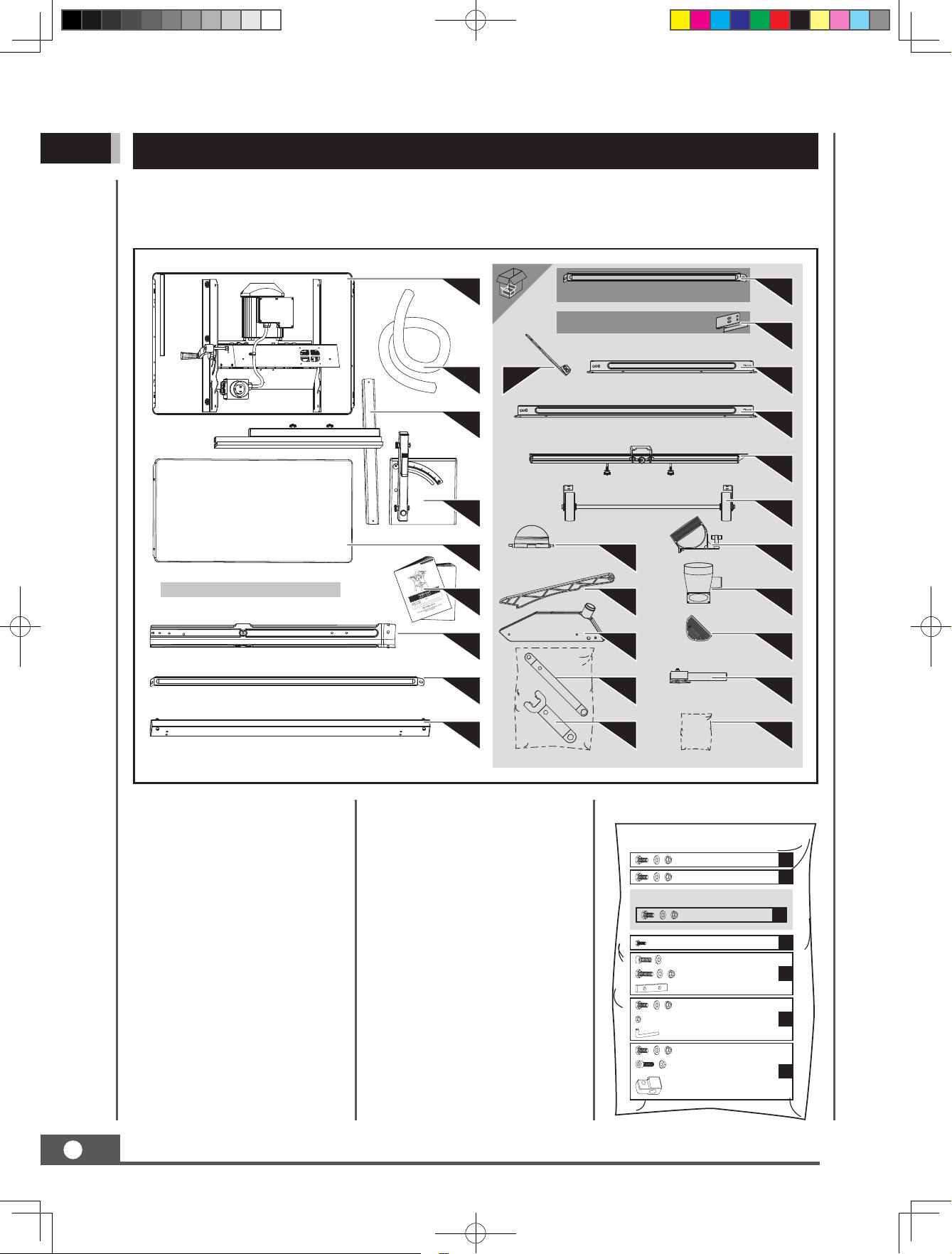
CONTENTS SUPPLIED
The table saw comes partially assembled and is shipped in carefully packed carton. After all the
parts have been removed from the carton, you should have:
(× 1, for model 65062 & 65063)
(× 2, for model 65066 & 65067)
(× 4)
(× 2)
1
(× 2, for model 65066 & 65067)
(for model 65066 & 65067)
12
2
3
(× 2)
(× 2)
10
11
13
14
(× 2)
15
4
5
6
7
17
19
21
16
18
20
22
(× 4)
8
23
(× 2)
24
1. Main Machine
2. Hose
3. Rip Fence
4. Miter Gauge
5. Bench Extension (65062, 65063
× 1 / 65066, 65067 × 2)
6. Operator’s Manual
7. Leg (× 4)
8. Long Support Strut (× 2)
9. Guide Rail
10. Short Support Strut (× 2, only
65066, 65067 equipped)
11. Hose Holder
12. Guide Rail Support
9
Bracket (× 2)
13. Short Centre Brace (× 2)
14. Long Centre Brace (× 2)
15. Side Rail
16. Transporting Wheel
17. Rip Fence Locker
18. Push Stick 2
19. Push Stick 1
20. Suction Piece
21. Saw Blade Guard
22. Rubber Foot (× 4)
23. Ring Spanner
24. Transport Handle (× 2)
25. Saw Blade Key
25
26
26. Hardware Bag, Including
M6 × 12
M6 × 12
(Only Model 65066, 65067 use)
M6 × 12
M4 × 10
M6 × 16
M6 × 20
M6 × 12
M6
M6 × 12
M6 × 30
18
×
A
10
×
B
17
×
B
4
×
C
4
×
4
×
D
1
×
A
4
×
2
×
E
1
×
A
2
×
2
×
F
2
×
8
65063UK00M100.indd 8 2020/5/27 9:38:42
TABLE SAW
Page 9
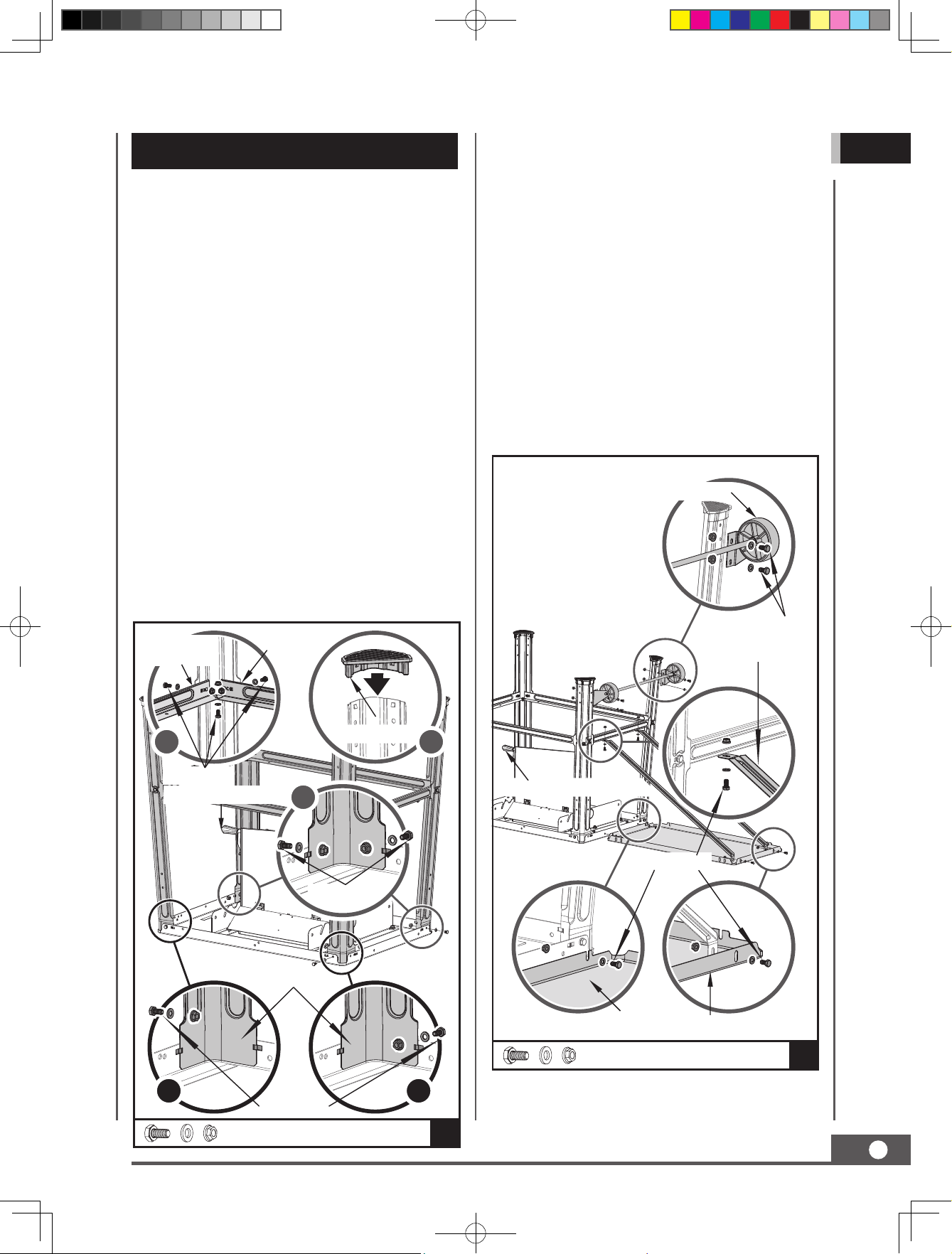
ASSEMBLY
This table saw was partially assembled at the
factory. To assemble your machine follow the
below instructions.
Support Legs & Long / Short Centre Braces
1. Turn the saw and place it on the floor with
the bench facing down.
Rear Bench Extension
1. Align the rear bench extension flush with the
saw bench.
2. Pushing the rear extension onto the sawing
bench using bolts M6×12 and loosely fasten
the flat washers and nuts M6.
3. Screw the long support struts to the bench
extension and short centre brace with bolts
M6×12, washers 6 and nuts M6.
GB
2. Fasten the four base legs onto the bench.
See illustration 1 & 2, only need to assemble
one bolt, washer and nut in each leg. See
illustration 3, need two bolts, two washers
and two nuts for each leg. Tighten the bolts
slightly by hand.
3. Screw the long center braces and the short
center braces onto the base legs using the
bolts M6×12, washers 6 and nuts M6. Tighten
the bolts slightly by hand.
Make sure that the same braces face each other.
The short centre braces must be mounted
parallel to the operator's side of the saw.
4. Attach the four rubber feet onto the base legs.
Short Centre
Brace
(× 2)
4 5
Long Centre
Brace
(× 2)
Rubber Foot (
4)
×
4. Tight the bolts and nuts slightly by hand.
5. Fasten the wheel assembly to the rear base
legs using four hexagon bolts M6×12, washers
6, and nuts M6. Tighten all the bolts and nuts
slightly by hand.
Transporting Wheels
M6 × 12 (
Long Support
(× 2)
Strut
4)
×
M6 × 12 (
Crank (Working Area)
12)
×
3
Leg (
4)
×
1
M6 × 12 (
M6 × 12
M6 × 12 (
2)
×
Height Adjusting Handlebar
M6 × 12 (
4)
×
Bench Extension
M6 × 12
6)
×
10
×
B
2
18
×
A
TABLE SAW
9
65063UK00M100.indd 9 2020/5/27 9:38:43
Page 10
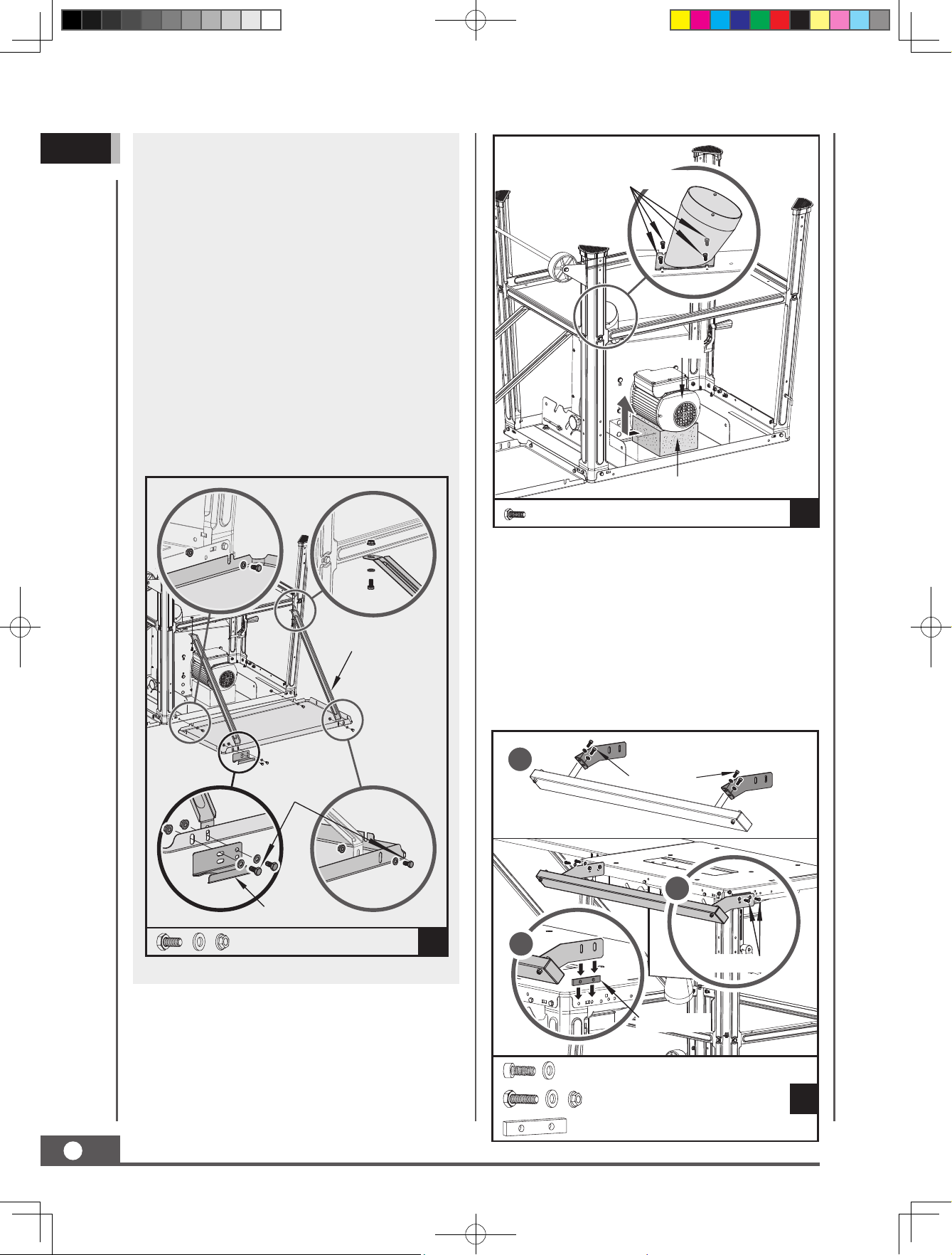
GB
Side Bench Extension (Only Model 65066,
65067 use)
1. Align the other side bench extension
extension flush with the saw bench.
2. Pushing the side bench extension onto
the sawing bench using bolts M6×12 and
loosely fasten the flat washers and nuts M6.
3. Screw the short support struts to the
bench extension and long centre brace
with bolts M6×12, washers 6 and nuts
M6. See below illustration 1, the hose
holder will be fixed with bench extension
and long support strut at the same time.
4. Tight the bolts and nuts slightly by hand.
M4 × 10 (
4)
×
Motor
Foam Support
M6 × 12 (
Hose Holder
Short Support
Strut
7)
×
(× 2)
M4 × 10
×
4
C
Guide Rail
1. Fit the two support brackets onto the guide
tube.
2. Screw the guide rail with the machine
using bolts M6×20, washers, and nuts. See
illustration 2 & 3, one spacer plate need to
be fixed with bench extension and guide rail.
1
M6 × 16 (
4)
×
3
M6 × 12
×
17
B
2
M6 × 20 (
Spacer Plate
4)
×
Suction Piece
1. Fasten the suction piece to the lower saw
blade guard using four hexagon bolts M4×10.
2. Remove the foam support from motor.
10
65063UK00M100.indd 10 2020/5/27 9:38:44
TABLE SAW
M6 × 16
M6 × 20
×
×
×
4
4
D
1
A
Page 11
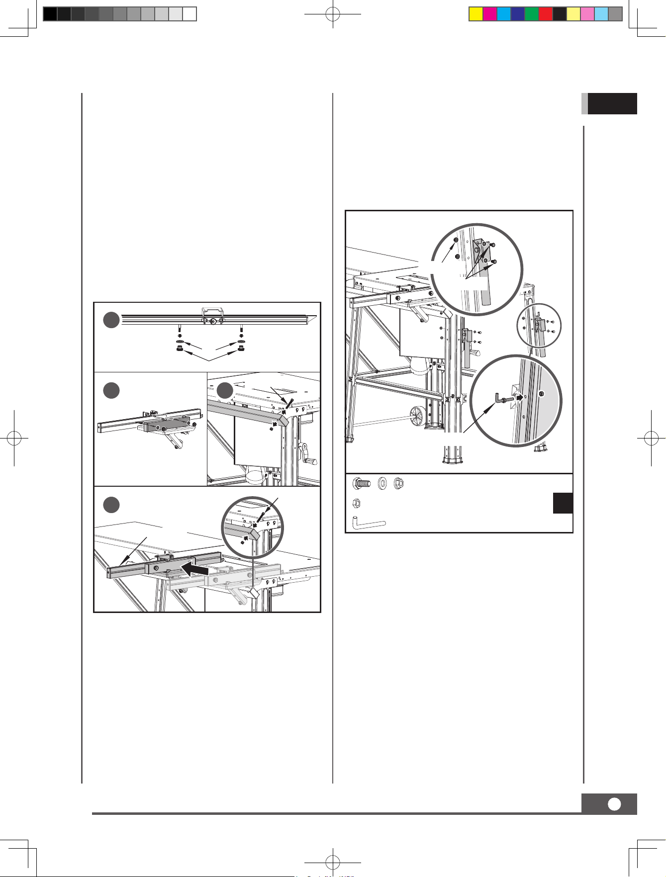
Miter Gauge
1. Remove the two nuts and washers from the
side rail. See illustration 1.
2. Insert two bolts in side rail into the holes in
the miter gauge, fasten them using nuts and
washers that were removed in step 1. See
illustration 2.
3. Remove the limit bolt and nut from guide
rail. See illustration 3.
4. Slide the miter gauge assembly along the
guide rail. See illustration 4.
5. Reattach the limit bolt and nut to the hole in
the guide rail.
1
Nut
Knurled Bolt
3. The two transport handles are attached at
the left and right leg at the front of the saw
using four hexagon bolts M6×12, washers 6
and nuts M6.
4. Fasten the hooked bolt to the right-hand
leg side using 2 nuts M6. the hook serves
for storing the saw blade key and the push
stick.
Flange Nut
M6 × 12 (
2)
×
GB
2
Limit Bolt
3
Limit Bolt
4
Side Rail
Transport Handles
1. Place the machine on its feet and firmly
tighten all bolts of bench, legs and braces
(except those of the wheel assembly).
2. Firmly tighten the wheel assembly in the
position where the wheels slightly touch the
ground.
Hooked Bolt
M6 × 12
M6
×
×
×
4
2
E
1
A
Saw Blade & Saw Blade Guard & Suction
Hose
1. Rotate the height adjusting handlebar to set
the blade to the max. cutting depth.
2. The distance between the saw blade and
the riving knife must be max. 3-8 mm.
See illustration 4. This distance had been
adjusted in the factory, user need to double
check, if beyond the max. distance, follow
the instruction in MAINTENANCE to do
adjustment.
TABLE SAW
65063UK00M100.indd 11 2020/5/27 9:38:46
11
Page 12
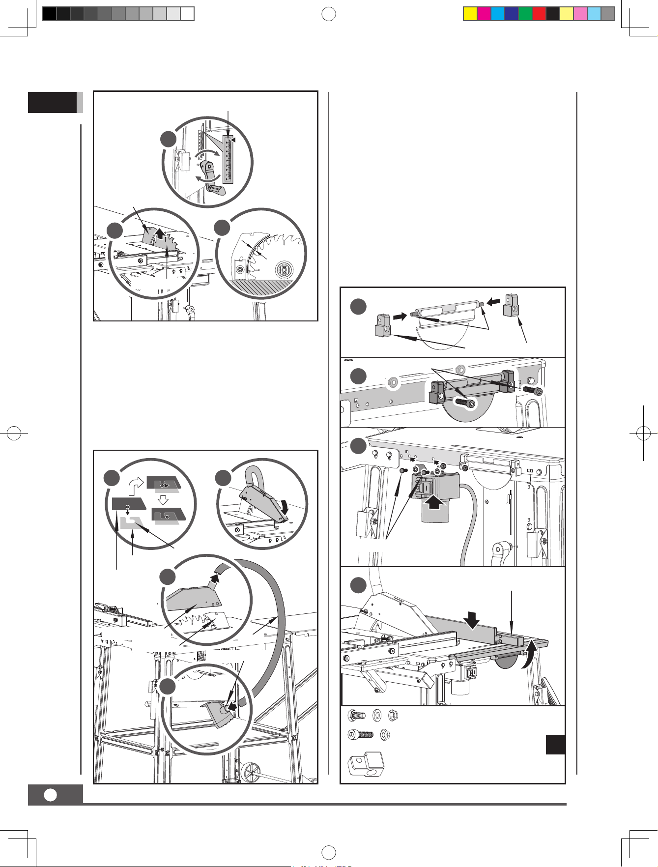
GB
Max. 3-8 mm
Cutting Height Indication
1
Rip Fence Locker
1. Slide the locker seats to the locker shaft. See
illustration 1.
2. Fasten the whole rip fence locker to the
bench table using two bolts M6×30 and
nuts. See illustration 2.
Riving Knife
2
Saw Blade
3
3. Fasten the suction hose to the suction
adapter and to the socket of the blade guard.
See below illustration 4 & 5.
4. Mount the saw blade guard on the riving
knife so that the screw in the blade guard
fits through the groove in the riving knife.
The blade guard will be able to move freely.
6
II.
7
2. Fasten the switch to the bench table using
two hexagon bolts M6×12, washers 6 and
nuts M6. See illustration 3.
2. Attach the rip fence onto the rip fence locker.
After reaching to the required cutting width,
then hold the locker up to secure the rip
fence in place. See illustration 4.
1
Shaft
M6 × 30 (
Rip Fence Locker Seat (
2)
×
2)
×
2
3
I.
Riving Knife
Saw Blade
Guard
Saw Blade Guard
Riving Knife
III.
L-Shaped Groove
5
4
Hose
Suction Adapter
M6 × 12 (
2)
×
4
M6 × 12
M6 × 30
Rip Fence
×
×
×
2
2
F
2
12
65063UK00M100.indd 12 2020/5/27 9:38:48
TABLE SAW
Page 13
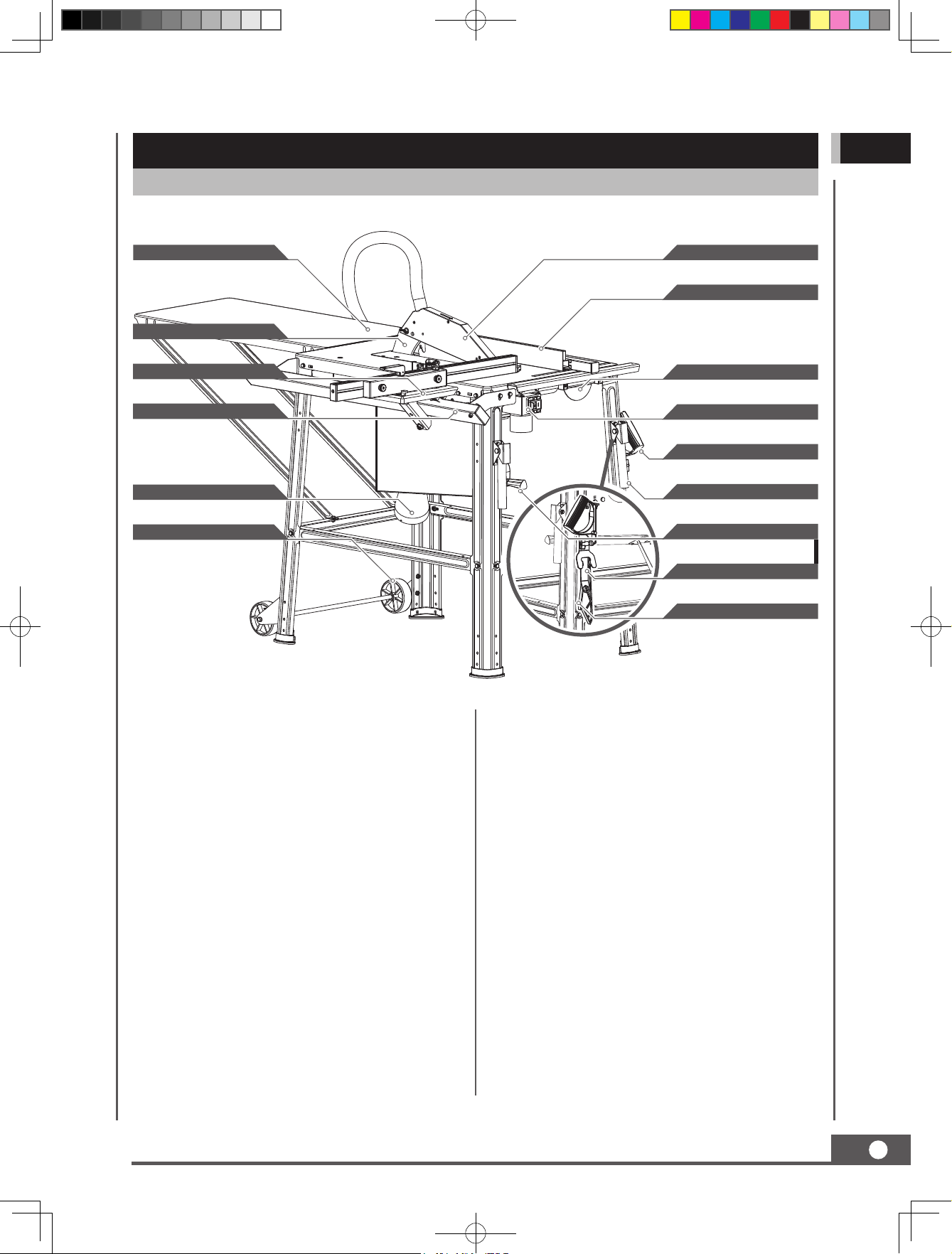
KNOW YOUR MACHINE
Features and Controls
GB
Bench Extension
Riving Knife
Miter Guage
Guide Rail
Suction Piece
Transporting Wheels
Saw Blade Guard
Rip Fence
Rip Fence Locker
Motor Switch
Self-tapping Push Stick
Transport Handle
Height Adjusting Handlebar
Saw Blade Key
Push Stick 1
ON/OFF Switch
The saw can be switched on by pressing the
green pushbutton.
The red pushbutton has to be pressed to
switch off the saw.
Blade Guard
Always keep the removable blade guard down
over the saw blade for through-sawing cuts.
Bench Extension
This bench extensions give the operator
additional support when cutting wide
workpiece.
Riving Knife
A removable metal piece of the blade guard
assembly, slightly thinner than the saw blade,
which helps keep the kerf open and prevent
kickback.
Height Adjusting Handlebar
Use this handlebar to lower and raise the blade
for height adjustments or blade replacement.
Miter Gauge
The miter gauge aligns the wood for a cross
cut. The easy-to-read indicator shows the
exact angle for a miter cut.
Rip Fence
A sturdy metal fence guides the workpiece.
TABLE SAW
65063UK00M100.indd 13 2020/5/27 9:38:49
13
Page 14
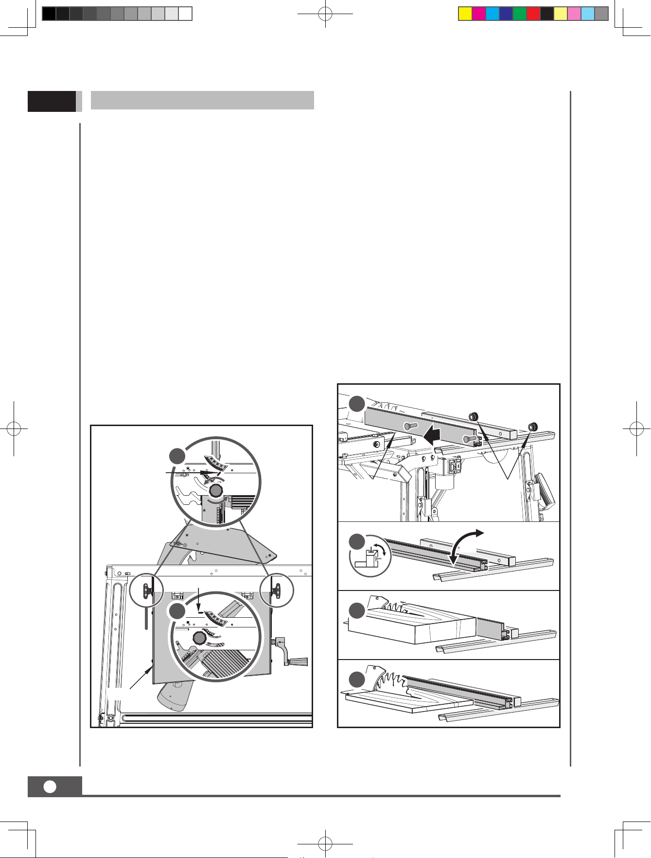
GB
Set Up
Change Blade Depth
Turn the height adjusting handlebar to set the
blade to the required cutting depth.
Counterclockwise: smaller cutting depth
Clockwise: larger cutting depth
After each new adjustment it is advisable to
carry out a trial cut in order to check the set
dimensions.
Change Blade Angle
Unplug the saw.
Loosen the bevel limitation screws in both
sides of chip box.
Set the desired angle on the scale by pressing
and turning the chip box.
Working with the Rip Fence
Set the Guide Height
The rip fence has two guide surfaces with
different heights.
For thick material you must use the rip fence
as shown in below illustration 1 & 3, for thin
material you must use the rip fence as shown
in below illustration 2 & 4.
To change over the stop rail to the lower
guide face you have to slacken the two
locknuts in order to disconnect the stop rail
from the rip fence.
Remove the two snap-head neck bolts
through the one slot in the stop rail and insert
in the other slot. Remount the stop rail with rip
fence.
The procedure for changing over to the high
guide face is similar.
Tighten the bevel limitation in the required
angle position.
1
Bevel Indicator
Bevel Indicator
2
0°
Min: 0°
45°
Max: 45°
1
LocknutsStop Rail
2
90°
3
4
Chip Box
14
65063UK00M100.indd 14 2020/5/27 9:38:49
TABLE SAW
Page 15
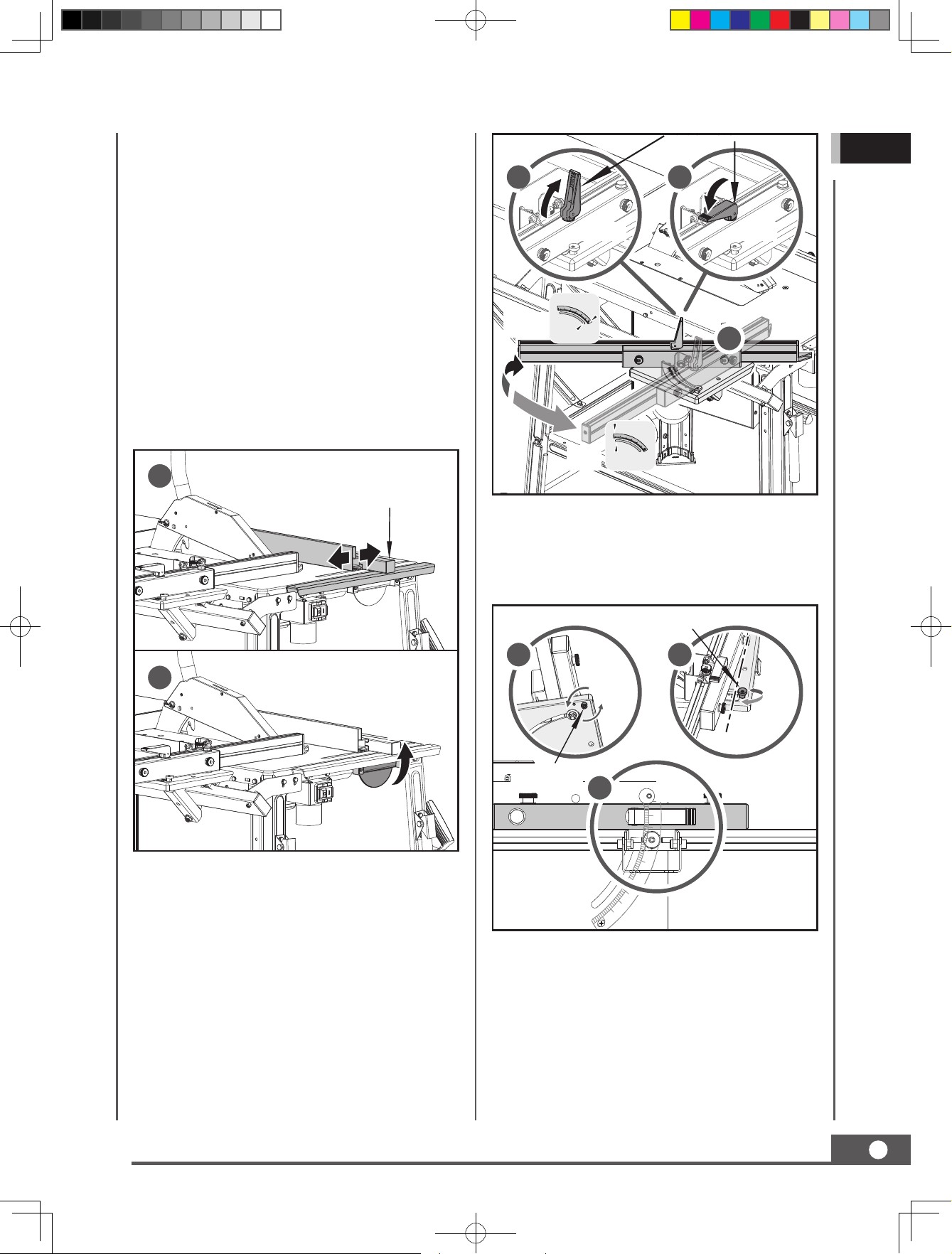
Tension Lever
Set the Cutting Width
GB
The rip hence has to be used when making
longitudinal cuts in wooden workpieces.
The rip fence should be mounted on the righthand side of the saw blade. Before move the
rip fence, release the rip fence locker. See the
position in illustration 1.
The rip hence can be set to the required
dimension with the help of the scale on the
bench table.
After reaching to the required dimension, hold
the rip fence locker up to fix rip fence in place.
See the position in illustration 2.
1
Rip Fence
1
45°
Unlock Lock
Max: 45°
Min: 0°
0°
3
2
When the gauge tube hit the eccentric wheel,
if the gauge tube hitting edge is not at the
zero, release the eccentric bolt and re-adjust
the eccentric wheel.
2
Lock
Use the Miter Gauge
The Miter gauge provide greater accuracy in
angled cuts. For very close tolerances, test
cuts are recommended.
The miter gauge can be turned 45°.
Loosen the tension lever.
Limit Eccentric
Wheel
1
3
0°
Socket Head
Screw
Workpiece Fastener
1. Open the workpiece fastener up.
2
0°
With the miter gauge in the miter gauge slot,
rotate the gauge until the desired angle is
reached on the scale.
Retighten the the tension lever.
2. Load the workpiece onto the worktable, and
against the side rail.
3. Push down the workpiece fastener against
the workpiece.
TABLE SAW
65063UK00M100.indd 15 2020/5/27 9:38:51
15
Page 16
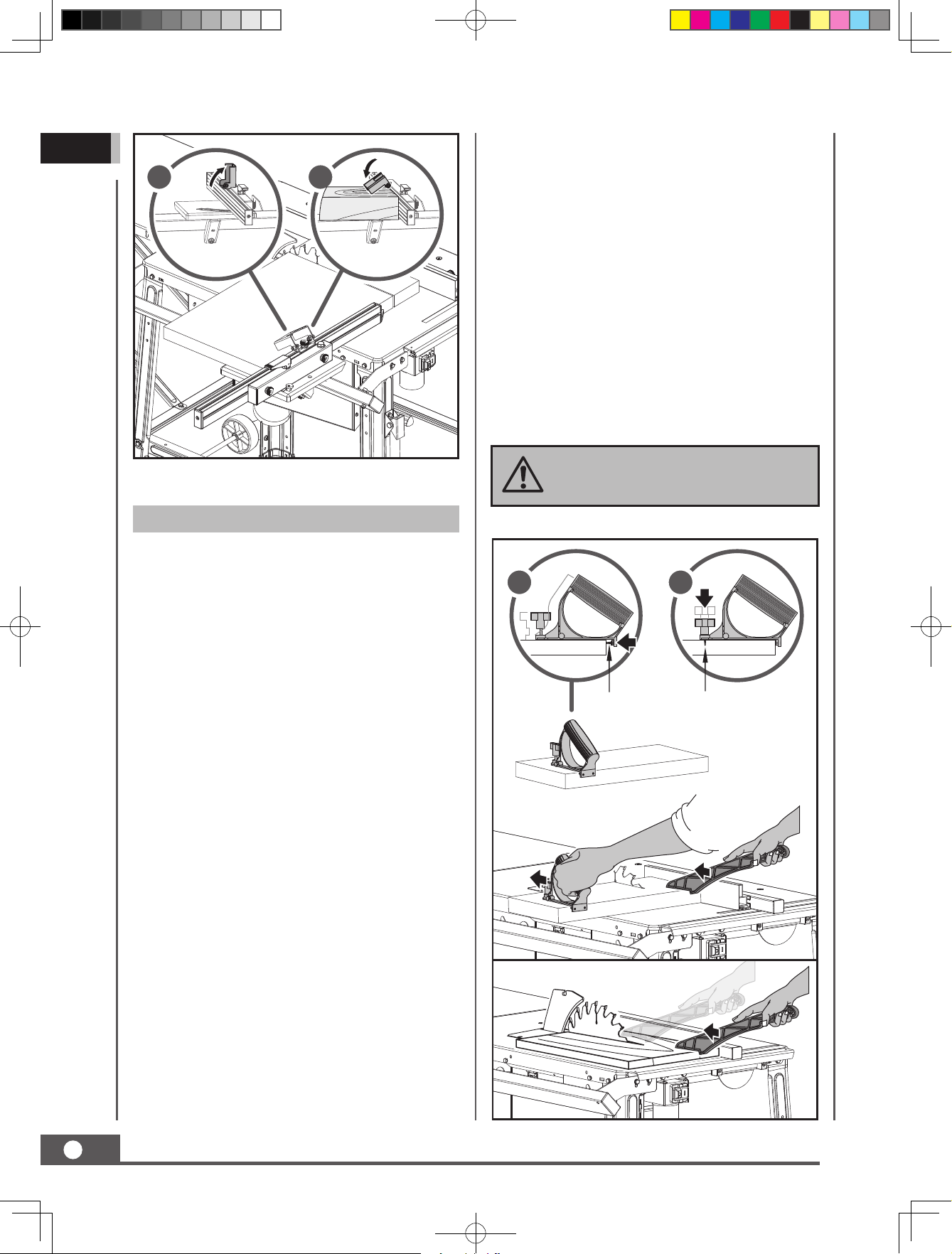
GB
1 2
Unlock Lock
Operation
Cutting Narrow Workpieces
Be sure to use a push stick when making
longitudinal cuts in workpieces smaller than
120 mm in width. A push stick is supplied with
the saw. Replace a damaged or worn push
stick immediately.
1. Adjust the rip fence to the width of workpiece
you require.
2. Feed in the workpiece with two hands.
Always use the push stick in the area of the
saw blade.
3. Always push the workpiece through to the
end of the riving knife.
Warning! With short workpiece, use
the push stick from the beginning.
Making Longitudinal Cuts
Longitudinal cutting is when you use the saw
to cut along the grain of wood.
Press one edge of the workpiece against the
rip fence while the flat side lies on the saw
table. The blade guard must always lower over
the workpiece. When you make a longitudinal
cut, never adopt a working position that is in
line with the cutting direction.
1. Set the rip fence in accordance with the
workpiece and the desired width.
2. Switch on the saw.
3. Place your hands (with fingers closed) flat
on the workpiece and push the workpiece
along the rip fence and into the blade.
4. Guide at the side with your left or right hand
(depending on the position of the rip fence)
only as far as the front edge of the saw
blade guard.
1 2
Self-tapping Screw
5. Always push the workpiece through to the
end of the riving knife.
6. The offcut piece remains on the saw blade
until the blade back in its position of rest.
7. Secure long workpiece against falling off at
the end of the cut.
16
65063UK00M100.indd 16 2020/5/27 9:38:52
TABLE SAW
Page 17
Making Angular Cuts
Angular cuts must always be made using the
rip fence.
MAINTENANCE
GB
1. Set the blade to the desired angle.
2. Set the rip fence in accordance with the
workpiece width and height.
3. Carry out the cut in accordance with the
workpiece width.
Making Cross Cuts
1. Press the workpiece firmly against the miter
gauge.
2. Switch on the saw.
3. Push the miter gauge and the workpiece
toward the blade in order to make the cut.
Warning! Always hold the guided
part of the workpiece. Never hold
the part which is to be cut off.
4. Push the miter gauge forward until the
workpiece is cut all the way through.
5. Switch off the saw. Do not remove the offcut
until the blade has stopped rotating.
Warning! Prior to any adjustment,
maintenance or service work
disconnect the mains power plug!
General Maintenance Measures
Keep all safety devices, air vents and the
motor housing free of dirt and dust as far as
possible. Wipe the equipment with a clean
cloth or blow it with compressed air at low
pressure.
We recommend that you clean the device
immediately each time you have finished using
it.
Clean the equipment regularly with a damp
cloth and some soft soap. Do not use cleaning
agents or solvents; these could attack the
plastic parts of the equipment. Ensure that no
water can seep into the device. The ingress of
water into an electric tool increases the risk of
an electric shock.
In order to extend the service life of the tool,
oil the rotary parts once monthly. Do not oil
the motor.
TRANSPORT
1. Turn off the power tool before any transport
and disconnect it from the power supply.
2. Apply the power tool at least with two
people, do not touch the table extensions.
3. Protect the power tool from knocks, bumps
and strong vibrations such as during
transport in vehicles.
4. Secure the power tool against overturning
and sliding
5. Never use the safety devices for handling or
transporting purpose.
Saw Blade Change
1. Ensure that the table saw is not connected
to the mains supply.
2. Use protective gloves. Do not touch the saw
blade with your bare hands.
3. Make sure that the saw blade has been
lowered all the way into the saw table. If
necessary, lower the saw blade by turning
the crank counterclockwise up to the stop
point.
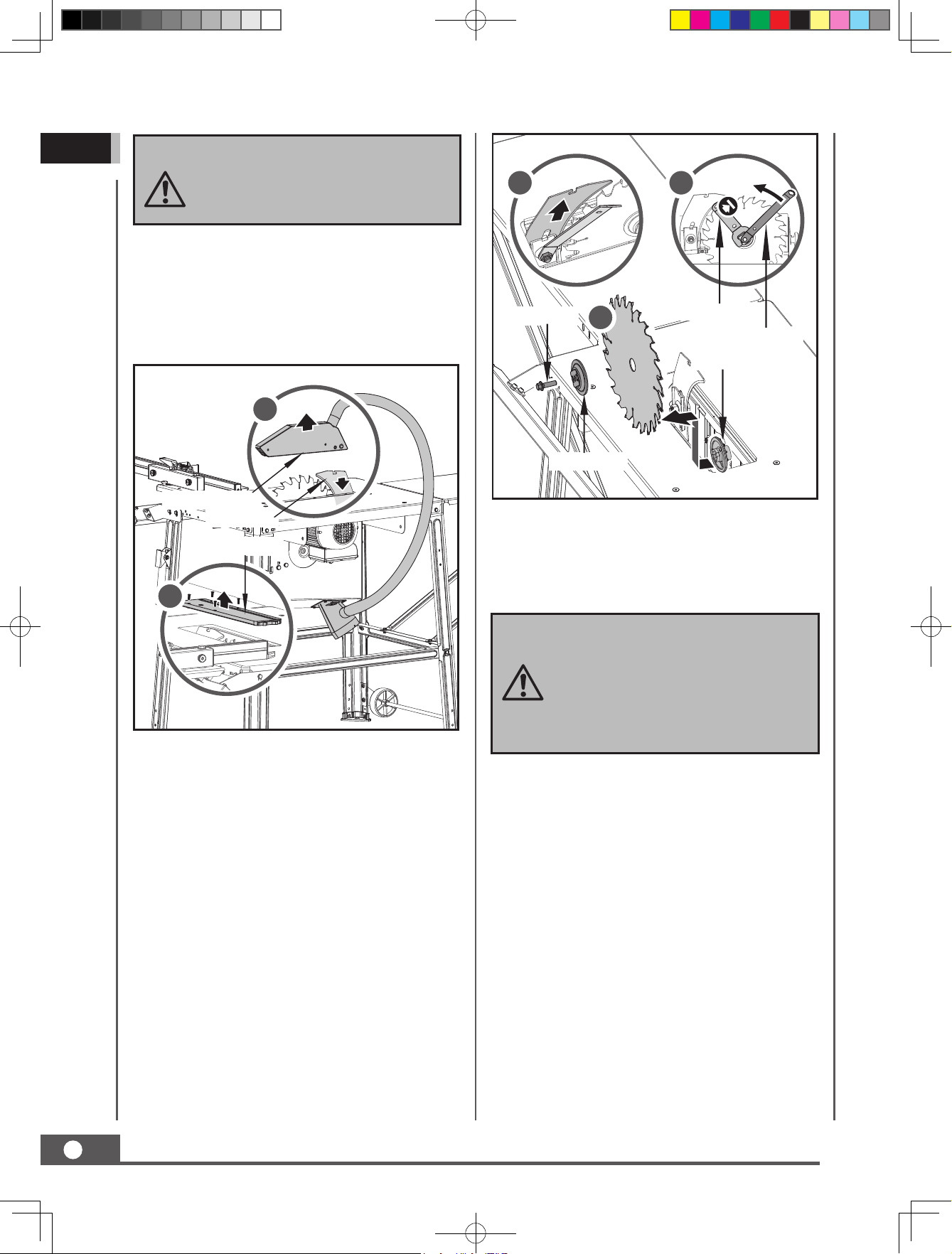
4. Remove the saw blade guard from the riving
knife. Gently pulling the saw blade guard
apart. See below illustration 1.
5. Loosen the four screws from bench insert
and remove the bench insert.
TABLE SAW
17
65063UK00M100.indd 17 2020/5/27 9:38:53
Page 18
GB
Always check the bench insert in the
process: Immediately replace the
bench insert if it is damaged or is no
longer flush with the saw table.
6. Make sure that the angle of the saw blade
is set to 0°.
4 5
7. Rotate the saw blade all the way out of the
saw table by turning the crank clockwise up
to the stop point.
1
Saw Blade Guard
Riving Knife
Bench Insert
2
Fixing Bolt
Blade Flange
6
Saw Blade Key
Ring Spanner
Drive Shaft
14. Clean the outer and inner saw blade flange
thoroughly before mounting a new saw
blade.
15. Mount a new saw blade on the drive shaft.
Pay attention to the rotational
direction: The cutting interface of
the teeth must be in the direction
of rotation (forwards). Usually, the
direction of rotation is indicated on
the saw blade.
18
8. Remove the riving knife by loosening the
clamp bolt in the clamping plate by turning
it clockwise a few revolutions and then
pulling the riving knife up and out. See
below illustration 4.
9. Attach the ring spanner to the fixing bolt.
See below illustration 5.
10. Fasten the blade flange with the saw blade
key. See below illustration 5.
11. Turn the fixing bolt in an anti-clockwise
direction using the ring spanner.
12. Carefully hold the saw blade with one hand
and remove the fixing bolt and the outer
saw blade flange from the drive shaft.
13. Now take the saw blade off of the drive
shaft and carefully pull it up and out of the
saw table.
TABLE SAW
16. Place the outer saw blade flange back on
the drive shaft. At the same time, make sure
that the outer saw blade flange is correctly
aligned.
17. Tighten the fixing bolt to the drive shaft by
hand.
18. Carefully turn the saw blade in the direction
of rotation: It must be exactly centred
and must not “wobble”. Check the correct
positioning of the saw blade and outer saw
blade flange and adjust the parts again if
the saw blade is not precisely centred.
19. Hold the blade flange in place with the
saw blade key spanner and turn the fixing
bolt with the ring spanner in a clockwise
direction.
65063UK00M100.indd 18 2020/5/27 9:38:54
Page 19
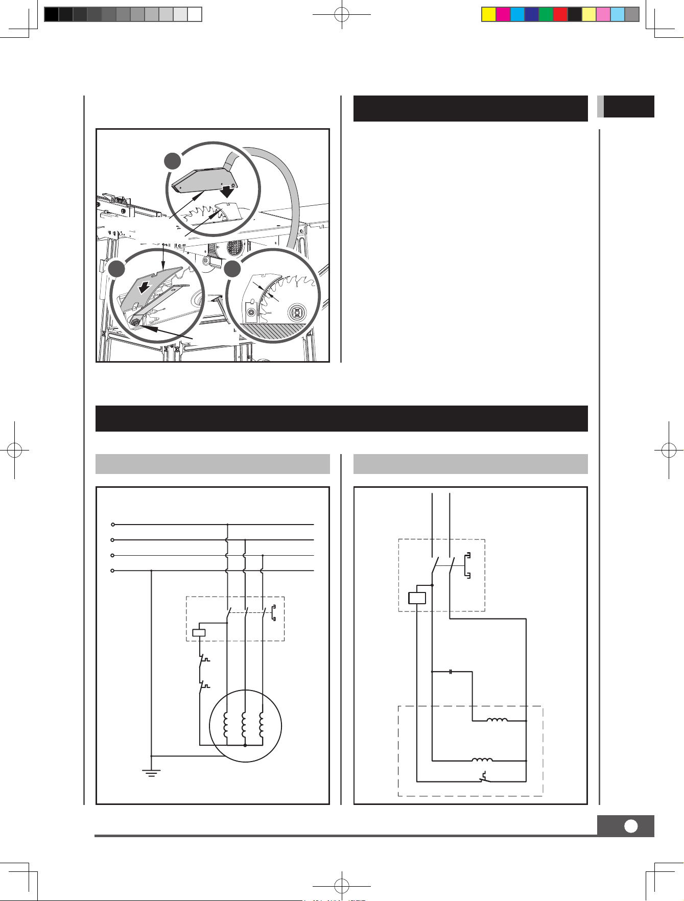
Max. 3-8 mm
20. Mount the riving knife, the table insert and
the saw blade guard.
3
Saw Blade Guard
Riving Knife
1 2
Clamp Bolt
STORAGE
Store the equipment and accessories in a dark
and dry place at above freezing temperature.
The ideal storage temperature is between 5
and 30°C. Store the electric tool in its original
packaging. Cover the electric tool in order to
protect it from dust and moisture.
GB
WIRING DIAGRAM
65060 (400V 3~ Motor) 65061 (230~240V Motor)
N L
L1
L2
L3
PE
0
1
Switch
CBB60
0
1
CBB60
Motor
65063UK00M100.indd 19 2020/5/27 9:38:54
Auxi. Winding
Main Winding
θ
TABLE SAW
19
Page 20
GB
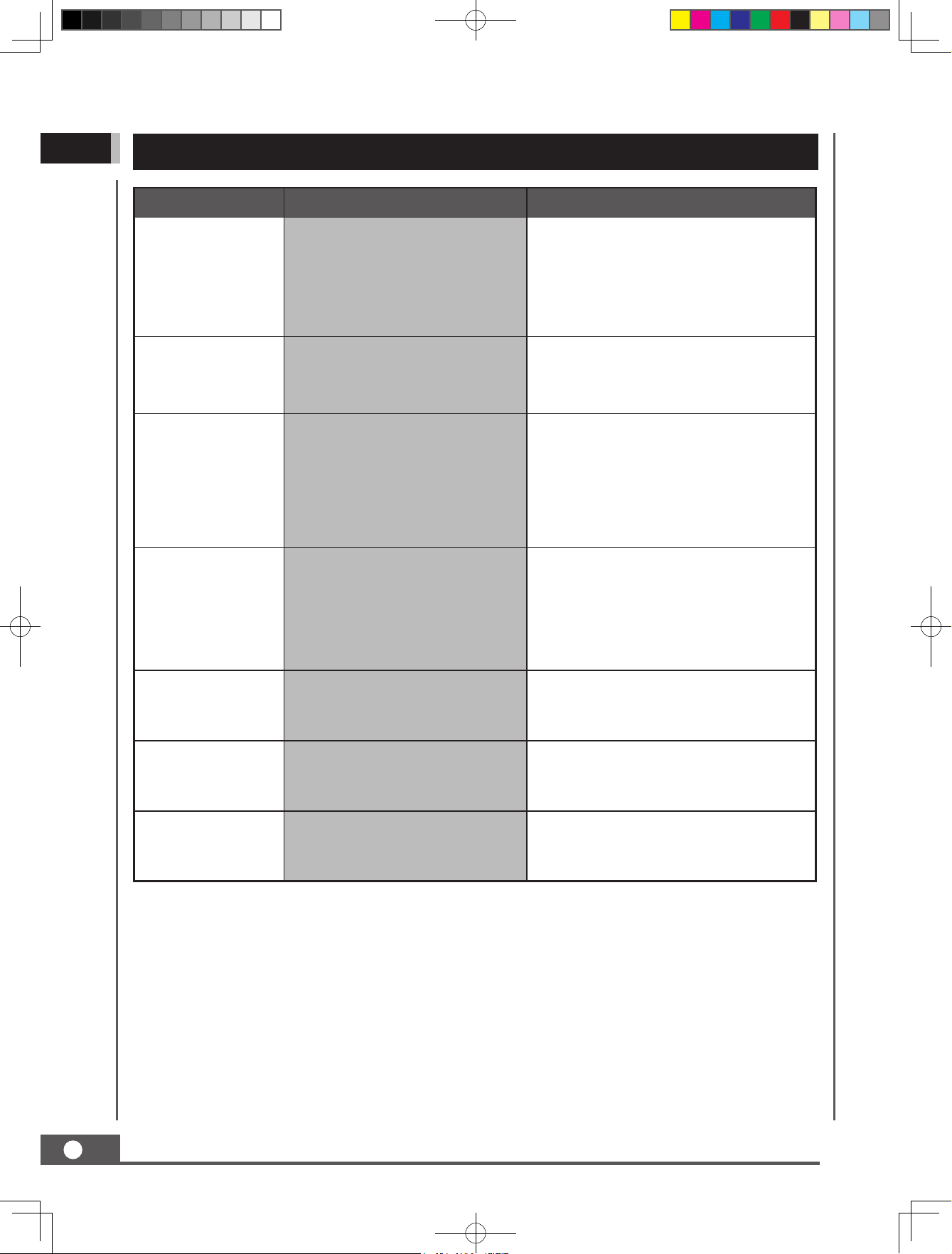
TROUBLE SHOOTING
Problem Cause Remedy
1. Fastening nut tightened
Motor does not
start
insufficiently
2. Extension cable defect
3. Connections on the motor or
switch defect
1. Check the mains fuse
2. Check the extension cable
3. Have it checked by an electrician
No Motor
output turns off
automatically
Excess vibration
Cutting binds or
burns work
Wood edges away
from rip fence when
ripping
Height/bevel
adjusting handwheel
is hard to turn
1. Overload by dull saw blade
2. Thermoprotection is triggered
1. Blade is out of balance
2. Blade is damaged
3. Saw is not mounted securely
4. Work surface is uneven
5. Blade is warped
1. Blade is dull
2. Work is fed too fast
3. RIp fence is misaligned
4. Wood is warped
Rip fence is misaglined Check and adjust the rip fence
Gears or screw post inside
cabinet are clogged with saw
dust
1. Insert a sharpened saw blade
2. Motor can be turned on again after
the cooling period.
1. Replace the blade
2. Replace the blade
3. Tighten all the hardware
4. Reposition on flat surface
5. Replace the blade
1. Replace t or Sharpen blade
2. Slow the feed rate
3. Align the rip fence
4. Replace the wood. Always cut with
convex side to table surface.
Clean the gears or screw post
Saw does not make
accurate 90° or 45°
cuts
20
65063UK00M100.indd 20 2020/5/27 9:38:54
TABLE SAW
Miter gauge is misaligned (Miter
Cuts)
Adjust the miter gauge
Page 21
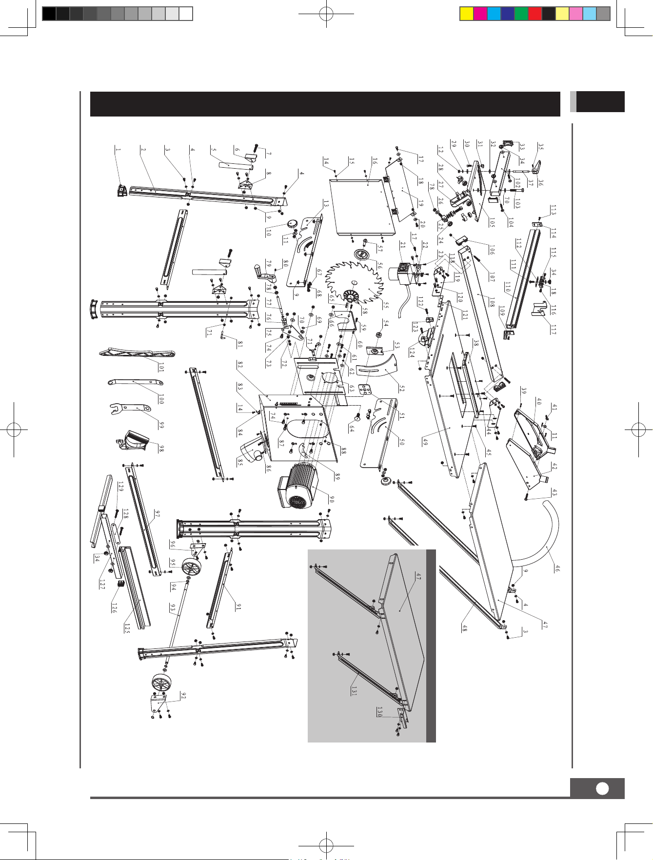
PARTS SCHEDULE
GB
Only Model 65066, 65067 use
TABLE SAW
65063UK00M100.indd 21 2020/5/27 9:38:56
21
Page 22
GB
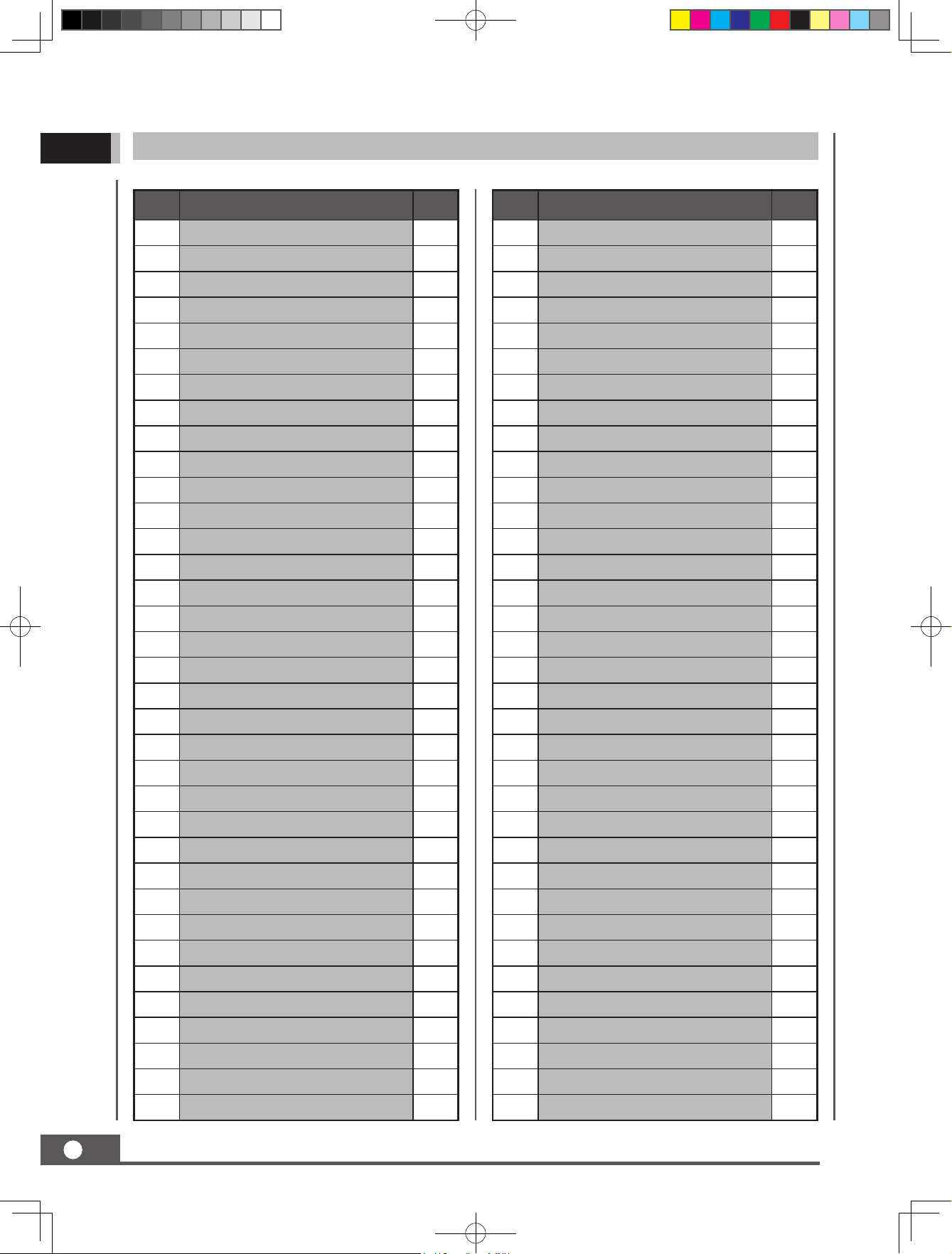
65062 / 65063 / 65066 / 65067 Parts List
No. Description Q'ty
1 Rubber Foot 4
2 Leg 4
3 Bolt 8.8 M6×12 41
4 Washer 6 54
5 Transport Handle Lever 2
6 Transport Handle Lever Cover 2
7 Bolt 8.8 M8×45 2
8 Transport Handle Seat 2
9 Flange Nut M6 57
10 Bevel Limitation Screw 2
11 Big Washer 8 11
12 Locknut M8 12
13 Front Guide Bracket 1
14 Screw M4×10 8
15 Lockwasher 4 5
No. Description Q'ty
36 Tension Lever 1
37 Locking Rod 1
38 Bench Insert 1
39 Screw ST2.9×25 3
40 Blade Guard-Left 1
41 Wing Nut M6 1
42 Blade Guard-Right 1
43 Bolt M6×40 1
44 Screw M4×16 4
45 Bolt M6×16 6
46 Suction Hose 1
47 Bench Extension 2
48 Long Support Strut 2
49 Bench Table 1
50 Rear Guide Bracket 1
16 Rear Connecting Plate 1
17 Bolt M6x16 8
18 Locknut M6 7
19 Rear Protective Plate 1
20 Big Washer 6 20
21 Switch 1
22 Switch Fixing Cover 1
23 Screw ST4.2×13 4
24 Bearing 6000-2RS 6
25 Guiding Shaft - Down 1
26 Screw M10×20 1
27 Screw M10×30 1
28 Bearing Guard 4
29 Spring Washer 8 1
30 Screw M6×16 1
31 Limit Eccentric Wheel 1
32 Sliding Table Washer 2
51 Riving Knife Sliding Seat 1
52 Riving Knife 1
53 Pressing Plate 1
54 Fixing Nut 1
55 Saw Blade 1
56 Outer Saw Blade Flange 1
57 Fixing Bolt 1
58 Inner Saw Blade Flange 1
59
Bolt 4.8 M5×20
60 Bushing 2
61 Bolt M6×20 4
62 Spring Washer 6 4
63 Motor Mounting Plate 1
64 Bolt M12×35 1
65 Flat Key 6×32 1
66 Guard Plate 1
67 Bolt M8×12 4
2
33 Fence Tube Cap 2
34 Locknut 5
35 Pin 4×18 1
22
65063UK00M100.indd 22 2020/5/27 9:38:57
TABLE SAW
68 Snap-head Neck Bolt 2
69 Circlip 10 1
70 Flat Washer 6
Page 23
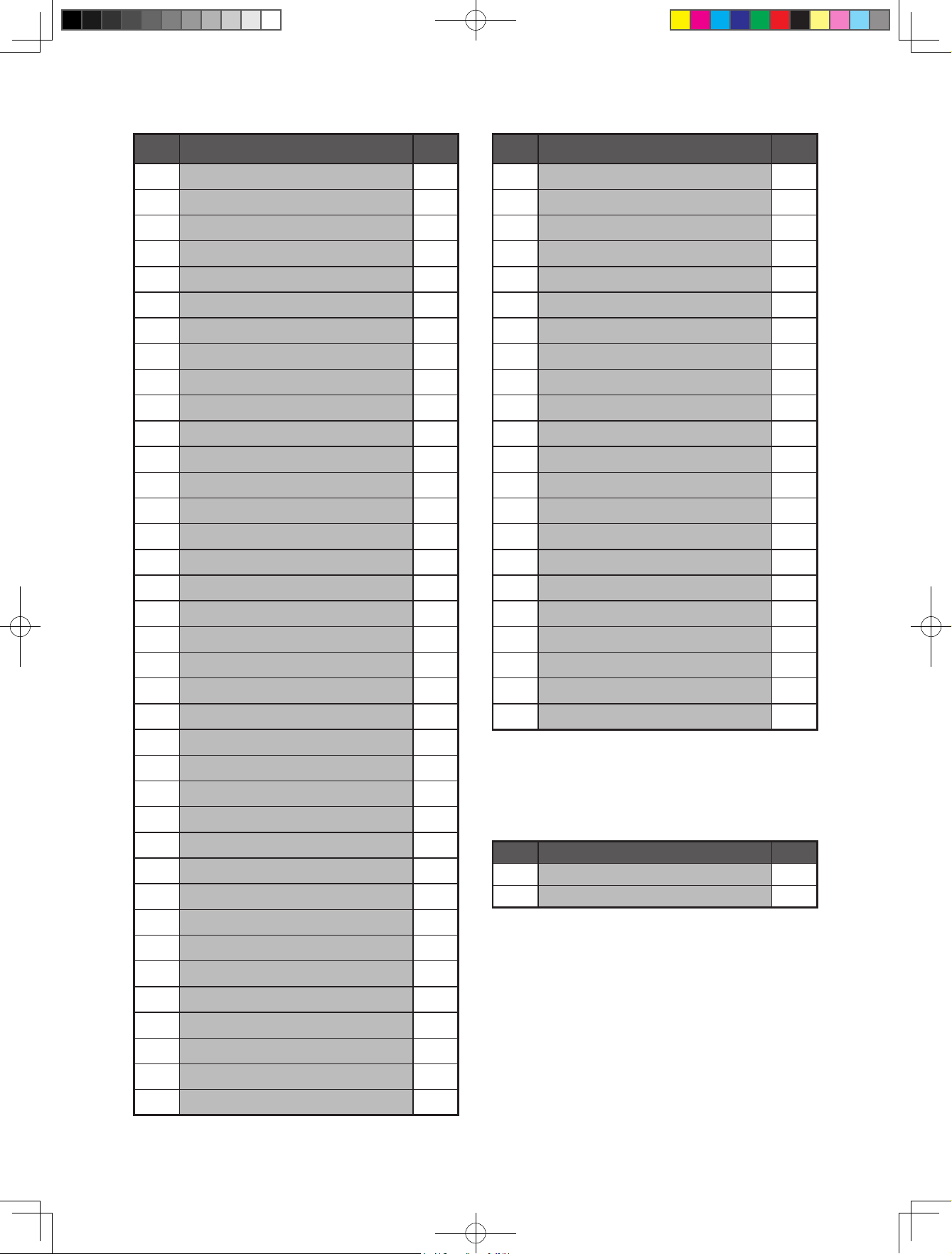
No. Description Q'ty
No. Description Q'ty
71 Height Indicator 1
72 Nut M6 3
73 Nut M8 2
74 Bolt 8.8 (cvc) M8x16 5
75 Guiding Connecting Plate 1
76 Connecting Plate 1
77 Height Adjusting Handlebar Rod 1
78 Thin Nut M10 2
79 Height Adjusting Handlebar 1
80 Screw M6×10 1
81 Hook 1
82 Chip Box 1
83 Flat Washer 4 2
84 Wiring Fixing Knob 1
85 Suction Piece 1
86 Bolt M4×10 4
87 Bolt 8.8 M8×30 1
108 Guide Rail 1
109 Side Rail- Front cap 1
110 Side Rail 1
111 Bolt M6×20 1
112 Sliding Plate 1
113 Screw ST4.8×16 2
114 Side Rail- Rear cap 1
115 Bracket 1
116 Screw M6×12 2
117 Workpiece Fastener 1
118 Screw M6×16 4
119 Guide Rail Support Bracket 2
120 Bolt M6×20 4
121 Spacer Plate 1
122 Bolt M6×30 2
123 Rip Fence Locker Seat 2
124 Rip Fence Locker 1
88 Locknut M5 2
89 Motor Seat Plate 1
90 Motor 1
91 Short Center Brace 2
92 Wheel Support- Left 1
93 Wheel Axle 1
94 Circlip 12 4
95 Wheel 2
96 Wheel Suppor- Right 1
97 Long Center Brace 2
98 Push Stick 2 1
99 Saw Blade Key 1
100 Ring Spanner 1
101 Push Stick 1 1
102 Fence Tube 1
103 Bolt M10×65 1
104 Bolt M6×45 2
125 Stop Rail 1
126 Tube Cap 2
127 Rip Fence 1
128 Long Washer 1
129 Bolt M6×50 2
Only Model 65066, 65067 use
No. Description Q'ty
130 Hose Holder 1
131 Short Support Strut 2
105 Miter Gauge 1
106 Guide Rail Cap 2
107 Screw M6×40 2
65063UK00M100.indd 23 2020/5/27 9:38:57
Page 24
65063UK00M100.indd 24 2020/5/27 9:38:57
 Loading...