

TIVAL FF4 Operating Instructions Manual
TIVAL Sensors GmbH
Protection class per IEC 529 with rubber grummed
IP 54
Protection class per IEC 529 with cable cland PG 13.5
IP 65
Operating temperature TS, plastic press. connector
0 … +50°C
Operating temperature TS, all other press. connector
-20 … +70°C
Resistance to vib ration (10 … 1000 Hz)
4g
Heating load (AC1; 230V AC)
16 A
Inductive load (AC15; 230V AC)
6 A
Inductive load (DC11; 230V DC)
0.1 A
Motor ratin g , full load (FLA)
10 A
Motor rating, lock ed rotor (LRA)
60 A
PS (bar/ PSI)
PT (bar/ PSI)
2 = 0.11 … 2 / V1 = 1½ ... 29
20 / 290
40 / 580
4 = 0.22 … 4 / V2 = 3 ... 58
24 / 348
40 / 580
8 = 0.5 … 8 / V3 = 7 ... 116
30 / 435
40 / 580
10 = 0.7 … 10
32
40
12 = 1 … 12
12
16
16 = 1 … 16 / V4 = 15 ... 232
36 / 522
48 / 696
30 = 3 … 30
30
42
32 = 2 … 32 / V5 = 29 ... 464
52 / 754
64 / 928
60 = 8 … 60 / V6 = 116 ... 870
100 / 1450
120 / 1740
120 = 16 … 120 / V7 = 232 ... 1740
200 / 2900
240 / 3480
250 = 30 … 250 / V8 = 435 ... 3625
400 / 5800
500 / 7250
blank = standard version
VdS = VdS relea sed version
③ = Diaphragm code
= D: perbunan
= A: stainless steel
= V: Viton
= P: plastic plunger
= Reset code
= A: Automatic reset
= D: man. reset min.
= R: man. reset max
= M: Non standard version
⑤ = Pressure connecti on
= H: G 3/8” female, s ilumin, DIN ISO 228/I
= Y: G 3/8” female, polyamid, DIN ISO 228/I
= G: G 1/4” fem ale, steel, DIN ISO 228/I
= I: G 1/2” fem ale, zinc die casting, D IN ISO 228/I
= F:1/ 4”-18 NPTF, ANSI B 1.20.3-1976
Oberdörnen 74
D-42283 Wuppertal
Tel: +49 202 7594080
Operating instructions
Pressure Control FF4
www.tival-sensors.com
General information:
For use in industrial and commercial applications as air compressors, water pumps,
booster pum ps, f ire-fi ghting e quipme nt, o il sup ply equipment , high press ure cleaning
apparatus.
Safety instructions:
• Read operatin g instru ctions th orough ly. Failu re to comp ly can result in device
failure, system damage or personal injury.
• According to EN 13313 it is intended for use by persons having the
appropriate knowledge and skill.
• Do not exceed the specified maximum ratings for pressure, temperature,
voltage and current.
• Before installation or service disconnect all voltages from system and device.
• Ensure that design, installation and operation are according to European and
national standards/regulations.
• Protect against pulsations and liquid surges.
• Avoid extreme vibrations.
• Fix cable with stress-relief device.
Mounting location:
• Any direction
Installation:
• Fit pressure switch using the bracket on the bottom of the unit.
• Do not seal plastic pressure connector in threads – use O-ring instead.
Pressure Test:
After completion of installation, a pressure test must be carried out as follows:
- according to EN 378 for systems which must comply with European pressure
equipment dir ective14/68/EU.
- to maximum working pressure of system for other applications.
Warning:
• Failure to do so could result in loss of refrigerant and personal injury.
• The pressure test must be conducted by skilled persons with due respect
regarding the danger related to pressure.
Tightness Test:
Conduct a tightness test acc ording to EN 378-2 with appropriate equipment and
method to identify leakages of external joints.
Electrical connection:
Entire electrical connections have to comply with local regulat ions.
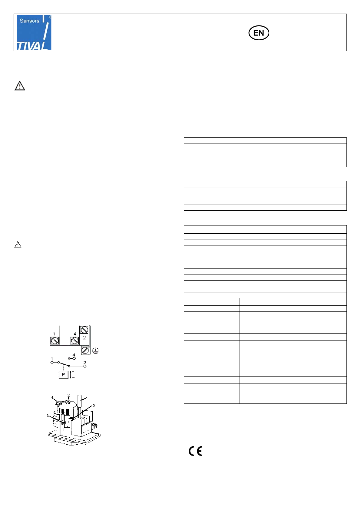
Wiring:
• Set upper switching-pressure with of adjusting screw 2. Pointer 3 will indicate.
• Set lower switching pressure by means of adjusting screw 4 -
upper switching pressure remains unchanged. Pointer 5 will indicate.
• Scales are not calibrated. Use manometer for
precise setting.
Reset:
• Standard version (FF 4-...DAH): Automatic reset after pressure decrease below
lower switch point
• Version with manual reset (FF 4-…DRH or DDH): pressure decrease below
upper or increase above lower switch point and reset button 1 (per Fig. 2)
depressed.
Technical Data:
Electrical Rating
Type code FF4 -① ② ③④⑤ / FF444- ① ③④⑤
① = Pressure range (bar / PSI)
② = Version:
④
Fig.1:
Setting (Fig.2):
Standards:
• VDE 0660, IEC 947-5-1, all models
• LVD - 2014/35/EU: Harmonized standards: EN 60947-1, EN 60947-5-1
• UL/CSA File E85974-1/1: FF 4-… psi…, FF444…psi
• Released for fire fi ght ing equ ipmen t: F F4-2 Vd S, FF4 -2 VdS DR I, FF4-10 VdS,
Fig.2
FF4-10 VdS DMI, FF4-16 VdS
• acc. LVD
• RoHS 2011/65/E U : F F4 -…, FF444-…
• DNV-GL- Approval for certain types (FF4-…GL…)
• UBA KTW & DV G W W270 for wetted materials – pending (FF4-…DAY…)
Date: 14.02.2019 FF4-TIVAL_OI_ML_R07_0714701.docx
TIVAL Sensors GmbH
Schutzart nach DIN 40 050 / IEC 529 mit Gummitülle
IP 54
Schutzart nach DIN 40 050 mit Verschraubung PG 13.5 / M20
IP 65
Betriebstemperatur TS, Kunststoffdruckanschluss
0 … +50°C
Betriebste mperatur TS , alle andere n D r uc k a n s chlüsse
-20 … +70°C
Rüttelfestigkeit bei 10 … 1000 Hz
4g
Ohm’sche Last (AC1; 230V AC)
16 A
Induktive Last (AC15; 230V AC)
6 A
Induktive Last (DC11; 230V DC)
0.1 A
Motorstrom (FLA)
10 A
Blockierter Rotor (LRA)
60 A
=
PS (bar/ PSI)
PT (bar/ PSI)
2 = 0.11 … 2 / V1 = 1½ ... 29
20 / 290
40 / 580
4 = 0.22 … 4 / V2 = 3 ... 58
24 / 348
40 / 580
8 = 0.5 … 8 / V3 = 7 ... 116
30 / 435
40 / 580
10 = 0.7 … 10
32
40
12 = 1 … 12
12
16
16 = 1 … 16 / V4 = 15 ... 232
36 / 522
48 / 696
30 = 3 … 30
30
42
32 = 2 … 32 / V5 = 29 ... 464
52 / 754
64 / 928
60 = 8 … 60 / V6 = 116 ... 870
100 / 1450
120 / 1740
120 = 16 … 120 / V7 = 232 ... 1740
200 / 2900
240 / 3480
250 = 30 … 250 / V8 = 435 ... 3625
400 / 5800
500 / 7250
② = Ausführung:
leer = Standardausführung
VdS = mit VdS Zulassung
=
= D: Perbunan
= A: Edelstahl
= V: Viton-Membrane
= R: Handrückstellun g m ax.
= M: Sonderausführung
⑤ =
= H: G 3/8” innen, Silumin, DIN ISO 228/I
= Y: G 3/8” innen, Polyamid, DIN ISO 228/I
= G: G 1/4” innen, Stahl, DIN ISO 228/I
= I: G 1/2” innen, Zinkdruckguß, DIN ISO 228/I
= F:1/ 4”-18 NPTF, ANSI B 1.20.3-1976
!
Oberdörnen 74
D-42283 Wuppertal
Tel: +49 202 7594080
Betriebsanleitung
Druckschalter FF4
www.tival-sensors.com
Beschreibung:
Zum Einsatz in industriellen und gewerblichen Anwendungen, wie
Luftkompressoren, Wasserpumpen, Druckerhöhungsanlagen, Feuerlöscheinrichtu ngen, Ölför derungsanl a g en, Hochdruckreinigungsger äten
Sicherheitshinweise:
• Lesen Sie die Betriebsanleitung gründlich. Nichtbeachtung kann zum
Versagen oder zur Zerstörung des Gerätes und zu Verletzungen führen.
• Der Einbau darf gemäß EN 13313 nur von Fachkräften vorgenommen
werden.
• Die angegebenen Grenzwerte für Druck, Temperatur, Strom und Spannung
nicht überschreiten.
• Vor Installation oder Wartung sind die Anlage und das Bauteil spannungsfrei
zu schalten.
• Konstruktion, Installation und Betrieb der Anlage sind nach den
entsprechenden europäischen Richtlinien und nationalen Vorschriften
auszuführen.
• Von starke Pulsationen und Flüssigkeitsschläge fernhalten.
• Extreme Vibrationen vermeiden.
• Kabel mit Zugentlastung befestigen.
Einbaulage:
• beliebig
Installation:
• Druckschalter auf ebener Fläche befestigen; hierzu können die zwei
Schrauböffnungen an der Konsole benutzt werden.
• Kunststoffdruckanschluss nicht im Gewinde abdichten - geeigneten Dichtring
verwenden.
Druck Test:
Nach der Installation ist ein Drucktest durchzuführen:
- gemäß EN 378 für Geräte, die die Europäische Druckgeräterichtlinie
2014/68/EU erfüllen sollen.
- mit dem maximalen Arbeitsdruck des Systems für alle anderen Anwendungen.
Warnung:
• Bei Nichtbeachten droht Kältemittelverlust und Verletzungsgefahr.
• Die Druckprüfung darf nur von geschulten und erfahrenen Personen
durchgeführt werd en.
Dichtheitsprüfung:
Die Dichthei tsprüfu ng ist mit geei gnetem Gerät und Method e gemäß EN 378 -2 so
durchzuführen, dass L eckstelle n sicher entdeckt werden.
Elektrischer Anschluss:
Für den gesamten elektrischen Anschluss sind die länderspezifischen Vorschriften
einzuhalten.
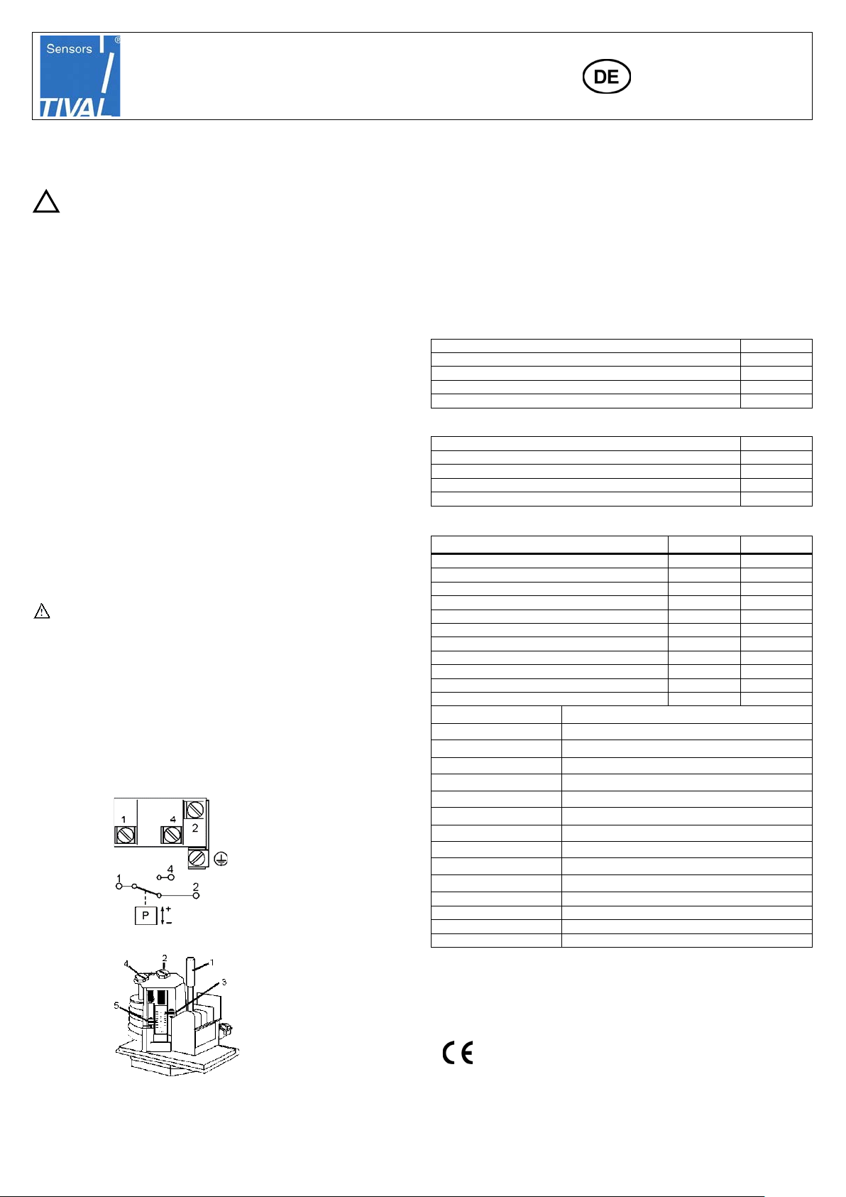
Kabelanschluss:
• Mit Einstellschraube 2 den oberen Schaltdruck einstellen.
Anzeige durch Zeiger 3.
• Mit Einstellschraube 4 den unteren Schaltdruck einstellen - der obere Schaltdruck
bleibt unverändert. Anzeige durch Zeiger 5.
• Die Einstellskala ist nicht geeicht. Für genauere Einstellung Manometer
verwenden.
Rückstellung
• Standardausführung (FF 4-…DAH): Automatische Rückstellung bei Druckabfall
unter unteren Schaltpunkt.
• Ausführung mit manueller Rückstellung (FF 4-…DRH oder DDH): Druckabfall
unter oberen oder Druckanstieg über unteren Schaltpunkt und Betätigung des
Rückstellknopfes 1 (Fig. 2).
Technische Daten:
Elektrische Schaltleistung:
Typschlüssel FF4-① ② ③④⑤ / F F444-① ③④⑤
①
Druckbereich (bar / PSI)
③
Ausdehnungskörper
= P: Kunststoffkolben
④= Rückstellung
= A: Automatisch
= D: Handrückstellung min.
Druckanschluss
Einstellung: (siehe Fig.2)
Fig.1:
Standards:
• VDE 0660, IEC 947-5-1, alle Modelle
• LVD - 2014/35/EU: Harmonisierte Standards: EN 60947-1, EN 60947-5-1
• UL/CSA File E85974-1/1: FF 4-… psi…, FF444…psi
• Zulassung für F e ue rl ös chanl age n: F F 4-2 VdS, FF4-2 VdS DRI, FF4-10 VdS, FF 4-
10 VdS DMI, FF4-16 VdS
• gem. LVD
Fig.2:
• RoHS 2011/65/E U : F F4 -…, FF444-…
• DNVGL- Zulassung für bestimmte Typen (FF4-…GL…)
• UBA KTW & DVGW W270 für medienberührende Materialien – in Bearbeitung
(FF4-…DAY…)
Date: 14.02.2019 FF4-TIVAL_OI_ML_R07_0714701.docx
 Loading...