

Page 1

EN
Product Manual
UNIT ONE TP550 220x90 TP552 Ø160 TP554 Ø150 TP 556 Ø180
UNIT TWO TP551 220x90 TP553 Ø160 TP555 Ø150 TP557 Ø180
Trimbox NO Filter
ventilation systems
®
Page 2

Warnings, Safety Information and Guidance
Important information
1. Installation of the appliance and accessories must be carried out by a qualied and
suitably competent person and be carried out in clean, dry conditions where dust
and humidity are at minimal levels.
2. Installation and maintenance personnel must wear suitable safety clothing to minimise the accident risk.
3. This manual covers the installation and maintenance of the Titon® Trimbox NO
Filter® system.
4. The unit must be stored in a clean and dry environment. Do not install the appliance
in areas where the following may be present or occur;
• Excessive oil or grease laden atmosphere,
• Corrosive or ammable gases, liquids or vapours,
• Ambient temperatures above 80°C or below -5°C,
• Humidity levels above 90% or is a wet environment.
5. The appliance is not suitable for installation to the exterior of the dwelling.
6. This appliance can be used by children aged from 8 years and above and persons
with reduced physical, sensory or mental capabilities or lack of experience and
knowledge if they have been given supervision or instruction concerning use of the
appliance in a safe way and understand the hazards involved.
7. Children should be supervised to ensure that they do not play with the appliance.
8. Ensure that external grilles are located away from any ue outlet, in accordance with
relevant Building regulations.
2
2
Page 3

Titon® Recommend
1. Any exible ducting used must be pulled taught;
2. Ducting must be installed in such a way that resistance to airow is minimised;
3. Duct joints to the unit’s duct ports must be xed using a method that ensures a long term seal is achieved.
Handling
1. Before o-loading products, please ensure that the means of transport/ lifting is suitable to accommodate the
required weight and size capacity;
2. Manually handle unit in accordance with the 89/391/EEC-OSH standard (and associated updates) and/or local
regulations.
Packing Contents
Inspect the unit when taking delivery. Check the unit for damage and that all accessories have been supplied.
Package supplied with:-
Trimbox NO2 Filter® system;
Product Manual x 1;
3mm Hex Key with inset magnet x 1.
Any shortages or damage must be immediately reported to the supplier
3
Page 4

Contents
Warnings, Safety Information and Guidance
Important information . . . . . . . . . . . . . . . . . . . . . . . . . . . . . . . . . . . . . . . . . . . 2
Titon® Recommend. . . . . . . . . . . . . . . . . . . . . . . . . . . . . . . . . . . . . . . . . . . . . . 3
Handling. . . . . . . . . . . . . . . . . . . . . . . . . . . . . . . . . . . . . . . . . . . . . . . . . . . . . . . 3
Packing Contents . . . . . . . . . . . . . . . . . . . . . . . . . . . . . . . . . . . . . . . . . . . . . . . .3
Product Overview
Product Description. . . . . . . . . . . . . . . . . . . . . . . . . . . . . . . . . . . . . . . . . . . . . . 5
Component Identication. . . . . . . . . . . . . . . . . . . . . . . . . . . . . . . . . . . . 5
Dimensions. . . . . . . . . . . . . . . . . . . . . . . . . . . . . . . . . . . . . . . . . . . . . . . . . . . . . 6
Port Size(s) . . . . . . . . . . . . . . . . . . . . . . . . . . . . . . . . . . . . . . . . . . . . . . . .6
Installation
Trimbox NO Filter® . . . . . . . . . . . . . . . . . . . . . . . . . . . . . . . . . . . . . . . . . . . . . . 7
Mounting . . . . . . . . . . . . . . . . . . . . . . . . . . . . . . . . . . . . . . . . . . . . . . . . .7
Wall Mounting (Vertical Only) Ducting Behind Unit . . . . . . . . . . . . . .8
Ducting Connection
Airow Direction . . . . . . . . . . . . . . . . . . . . . . . . . . . . . . . . . . . . . . . . . . . . . . . . 9
Ducting Connection . . . . . . . . . . . . . . . . . . . . . . . . . . . . . . . . . . . . . . . . .9
Ducting Behind Unit . . . . . . . . . . . . . . . . . . . . . . . . . . . . . . . . . . . . . . . .9
Maintenance. . . . . . . . . . . . . . . . . . . . . . . . . . . . . . . . . . . . . . . . . . . . . .10
Filter Replacement . . . . . . . . . . . . . . . . . . . . . . . . . . . . . . . . . . . . . . . . . . . . .10
Prelter . . . . . . . . . . . . . . . . . . . . . . . . . . . . . . . . . . . . . . . . . . . . . . . . .10
Active Carbon Filters . . . . . . . . . . . . . . . . . . . . . . . . . . . . . . . . . . . . . . . 10
NO Testing Kit . . . . . . . . . . . . . . . . . . . . . . . . . . . . . . . . . . . . . . . . . . . . 10
Carbon Life Prediction Service . . . . . . . . . . . . . . . . . . . . . . . . . . . . . . . 10
How to Change Filters. . . . . . . . . . . . . . . . . . . . . . . . . . . . . . . . . . . . . . . . . . . 11
Disposal of Filters. . . . . . . . . . . . . . . . . . . . . . . . . . . . . . . . . . . . . . . . . . 11
Accessories and Spare Parts List
Removable Insulation Jacket . . . . . . . . . . . . . . . . . . . . . . . . . . . . . . . . 12
Filters. . . . . . . . . . . . . . . . . . . . . . . . . . . . . . . . . . . . . . . . . . . . . . . . . . . . 12
Fitting Kit . . . . . . . . . . . . . . . . . . . . . . . . . . . . . . . . . . . . . . . . . . . . . . . .13
NO Testing Kit. . . . . . . . . . . . . . . . . . . . . . . . . . . . . . . . . . . . . . . . . . . . 13
Service Record
Log. . . . . . . . . . . . . . . . . . . . . . . . . . . . . . . . . . . . . . . . . . . . . . . . . . . . . . . . . . . 14
When this document
is viewed as a PDF the
headings & sub headings on
this page are hyper links to the content.
Additionally the page numbers in this
document are hyper links back to this
contents page.
4
Page 5

Product Overview
Product Description
The Titon® Trimbox NO Filter® reduces Nitrogen Dioxide (NO) which is prominently produced by exhaust gases from
Diesel engines. Due to this pollution arising in cities and urban areas there is a need to implement mitigation measures to
improve the indoor air quality (IAQ). The Titon® Trimbox NO® Filter is an eective means of reducing high NO levels down
to an acceptable level of 40µg/m3 as a mean annual concentration level.
The units are fully foam insulated. This reduces duct bound noise and thermal transmission and helps to avoid
condensation build up. Where the unit is installed in very cold spaces or if the outside air is below -5°C then a custom
designed removable insulation jacket is available from Titon® see Accessories and Spare Parts List.
Component Identication
Prelter
Carbon Filter
Retention Screws
Airow IN port
Filter Rails
Front Panel
Active Carbon Filters
5
Page 6

Dimensions
205
604
400
350
Port Size(s)
Rectangular Ports: 220mm x 90mm
Round Ports: Ø150mm, Ø160mm and Ø180mm
Service Void
Unit Dimensions (excluding ports)
6
Page 7

Installation
Trimbox NO Filter®
Read and observe the guidance & safety notices listed in Warnings, Safety information and Guidance .
The Trimbox Filter® is designed to be mounted in any orientation.
The mounting surface substrate must be suciently strong to support the unit.
Ensure there is sucient access around the NO unit for future maintenance.
Do not ‘box-in’ the unit making access to the unit dicult for maintenance and repair.
Mounting
1. Mark positions of the mounting holes onto the mounting surface using dimensions as shown.
2. Prepare the mounting surface in the positions specied for four Ø8mm xings. Fixings must be suitable for the
mounting surface substrate and the weight of the unit. Fixings are not supplied due to the variation in materials. For
advice on suitable xings contact your local specialized xings dealer.
3. Mount the unit using selected xings.
324.5
722
Fixing Positions
7
Page 8
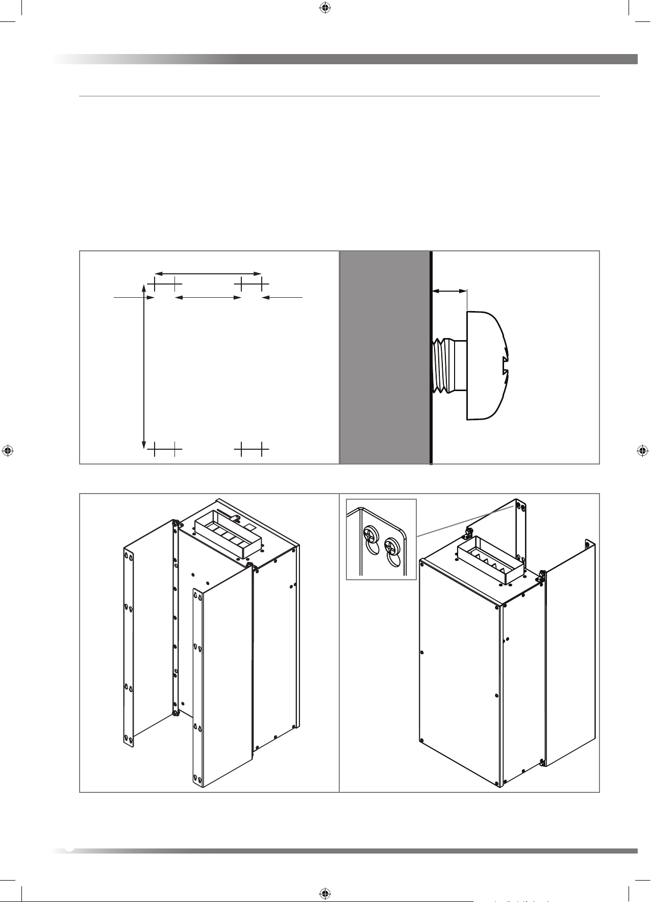
Wall Mounting (Vertical Only) Ducting Behind Unit
1. Attach the mounting brackets to the unit using M8 xings provided.
2. Mark positions of mounting holes onto wall using dimensions as shown.
3. Prepare the wall in the positions specied for eight Ø6mm xings at the marked positions. Fixings must be suitable
for the mounting surface substrate and the weight of the unit. Fixings are not supplied due to the variation in
materials. For advice on suitable xings contact your local specialized xings dealer.
4. When tting screws position the head leaving between 2mm and 4mm gap between wall and underside of head, see
illustration.
5. Guide slots in mounting bracket over xing screw heads. Lower the unit so that the xing comes to rest in the slots in
the mounting brackets ensuring that all xings heads are within the slots.
6. Connect ducting in the method shown opposite.
500
324.5
(284.5)(20) 20
Fixing Positions
MIN 2mm
MAX 4mm
Fixing Screw
8
Rear
Front
Page 9

Ducting Connection
Airow Direction
The Trimbox Filter® can be supplied with or without a prelter installed.The air to be ltered must pass though a prelter
before the active carbon lters, therefore if the Trimbox Filter® is supplied without a prelter it is very important that it is
tted so air supplied to the Trimbox Filter
Ducting Connection
The Trimbox Filter® has labels with icons indicating the airow IN and airow OUT ports
IN
This label denes that the port at this end of the unit must have airow going into the unit.
OUT
This label denes that the port at this end of the unit must have airow leaving the unit.
®
is from a HRV with integrated lters.
Ducting Behind Unit
Mounting Ducting Behind Unit
9
Page 10
Maintenance
Filter Replacement
Prelters should be replaced at least annually, or more regularly dependent on environmental conditions. To acertain if
the Active Carbon Filters require changing Titon recomend using the NO Testing Kit or the Carbon Life Prediction Service.
Prelter
Prelter, if installed, can be changed by the householder. Replacing the prelter for a higher grade (G4 to F7) will increase
the system resistance and may require re-comissioning to maintain the design airow rates
Active Carbon Filters
Changing of Active Carbon Filters should be carried out by experienced or trained personnel in accordance with safety
requirements as dened by the “Control of Substances Hazardous to Health" (COSHH) Regulations. i.e. Someone who fully
understands the design, operation and implications of the product and its use.
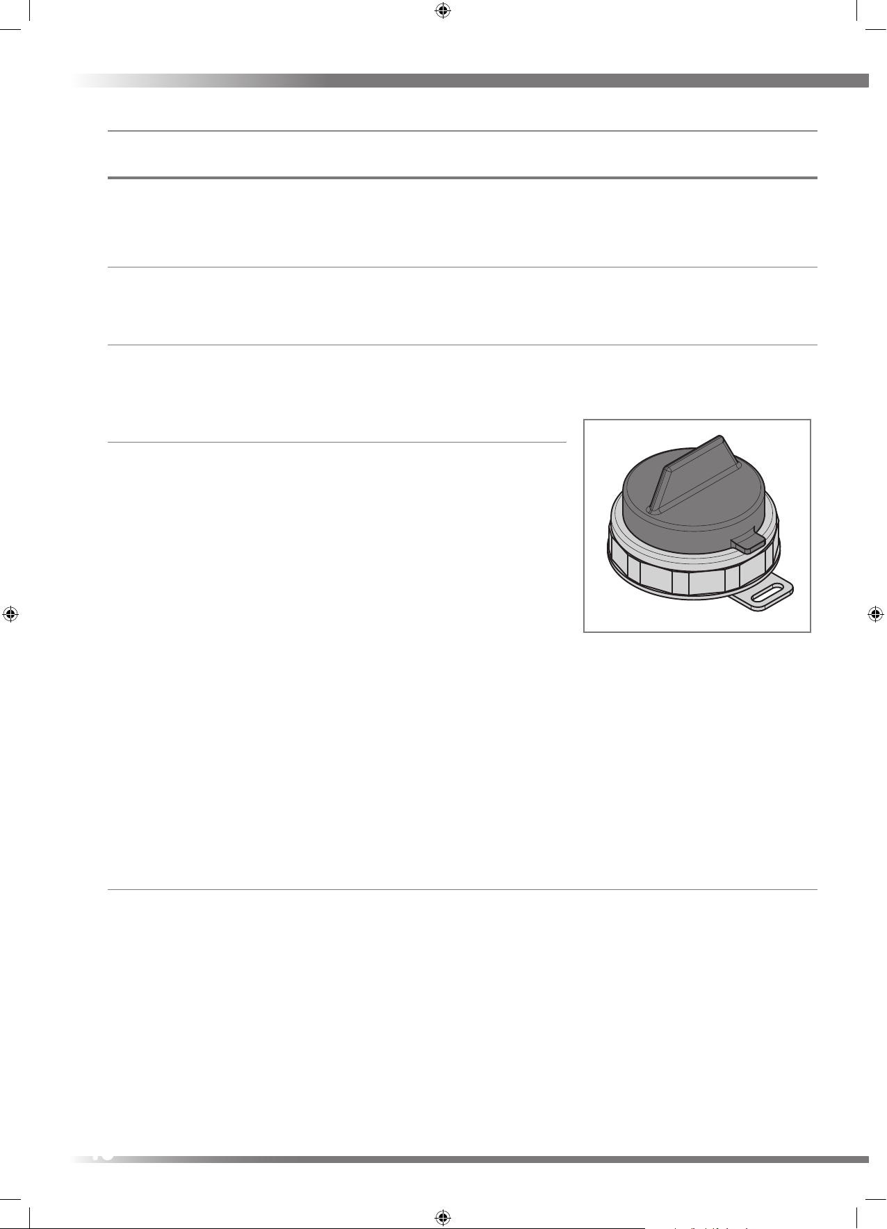
NO Testing Kit
A NO Testing Kit is available from Titon® that can be used to determine the
levels of NO within the property. The testing kit requires a minimum of 8
hours of exposure to the air and during this time the property must be sealed
from the outside air meaning all doors/window/vents closed and only the
ventilation system containing the NO lter to be in use. This will give an
accurate result for the performance of the NO lter. If the levels of NO are
greater than 40µg/m then the lter should replaced.
The 8hr exposure test kit consists of a plastic container with a removable
black plastic cap. If the testing kit is not to be used immediately after receipt
then it must be stored in a sealed polyethylene bag or similar and kept in a
refrigerator.
Instructions for use:
1. Apply sample identier that comes with the kit to the back of the sampler.
2. Fix the sampler to a vertical surface using adhesive tape, Blu-tack® or similar.
3. Remove the black cap and store in a safe place. There is a minimum of 8 hours of exposure and can be exposed up to
72 hours. At the end of the exposure period, replace cap and label the sample with the barcode label provided.
4. Ax the corresponding number label to the exposure sheet.
The testing kit should be returned within 2 weeks and must be stored in a refrigerator until dispatch.
Carbon Life Prediction Service
If requested Titon® can provide a Carbon Life Prediction Service. Part used lters can be sent to Titon® whereby they are
tested to determine the life expectancy of the carbon cells in use. If the lters are likely to have been exposed to hazardous
contaminants then Titon® must be informed of this. Please contact Titon® for more information.
10
Page 11
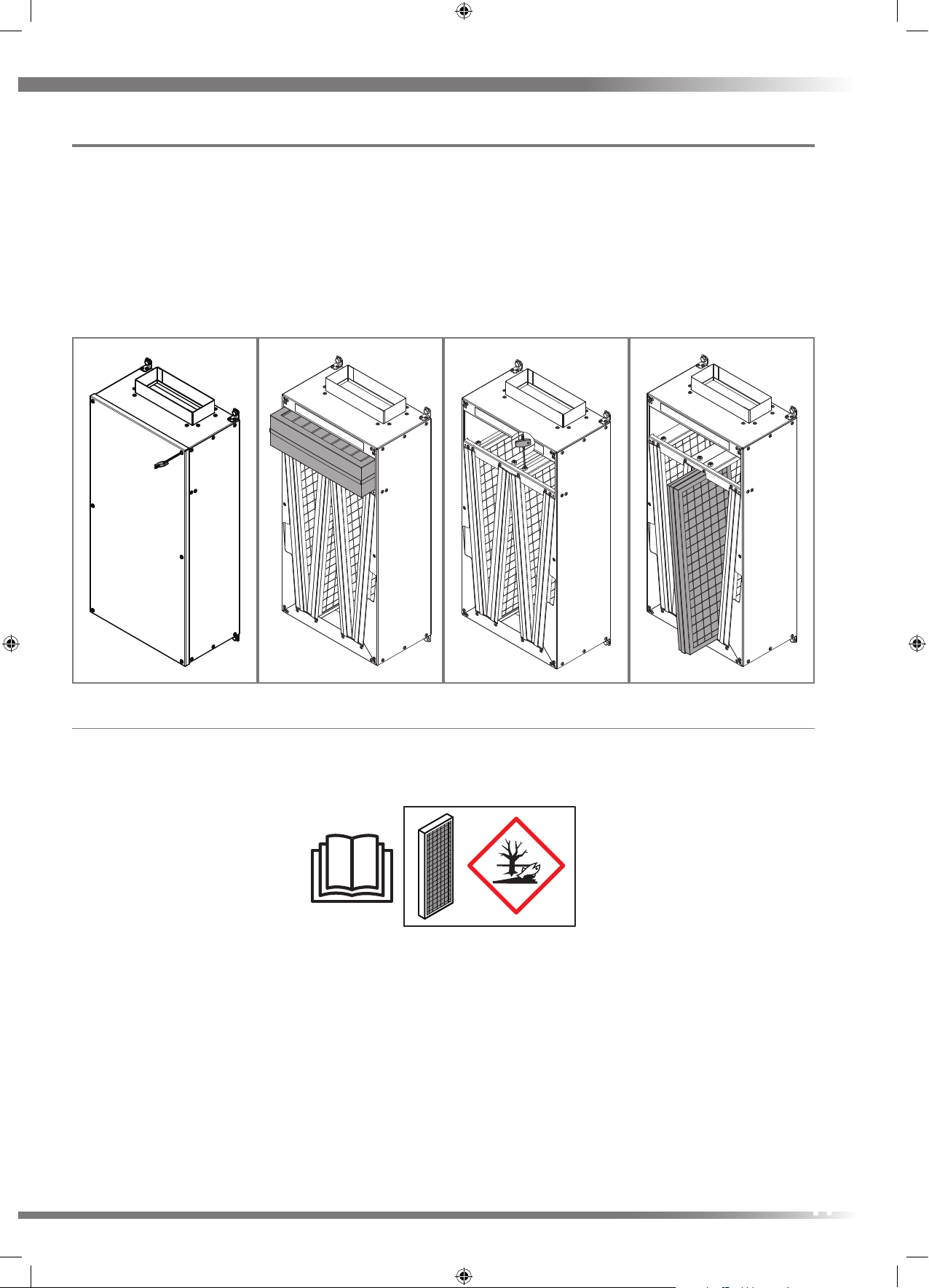
How to Change Filters
1. Remove Front Cover using 3mm Hex Key provided;
2. For Pre-Filter slide out lter from casing using handle attached to lter;
3. For Active Carbon Filters unscrew M5 screws using 3mm Hex Key on the top mounting rails as shown, and slide out
lter from casing. Only perform this action one lter at a time as lters may drop when mounted in a ceiling void;
4. Replace Active Carbon lters one at a time. Slide lter into casing and fully screw down the M5 screw in lter rail, do
not over tighten.
5. Replace Pre-Filter by sliding back into casing. Ensure the airow direction corresponds with
the direction arrow on lter;
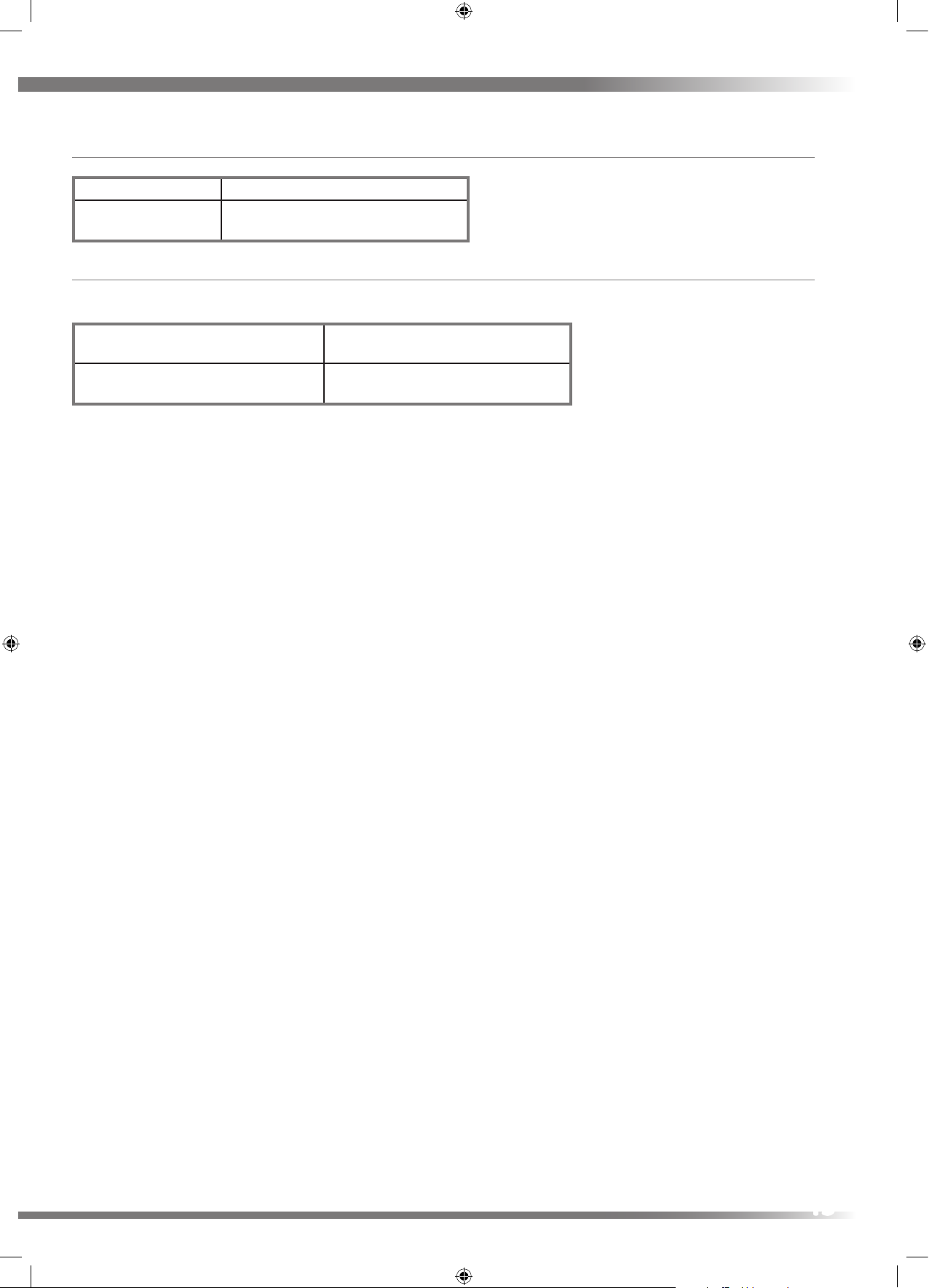
Disposal of Filters
The carbon within the lters are impregnated with chemicals and therefore has to be treated as specialist waste. The
disposal of the lters must be carried out by a specialist waste disposal company and not by the inhabitant of the property.
DO 5463 Iss 01
The Active Carbon Filters are Dangerous for the Environment.
Titon® do not oer a waste disposal service and therefore cannot accept lters for disposal, but can recommend the
following company:
Environmental Resource Group Tel: 0844 692 0000 Web: www.environmentalresourcegroup.com
11
Page 12

Accessories and Spare Parts List
Removable Insulation Jacket
Titon® can provided a custom designed removable
insulation jacket for the Trimbox NO Filter® which
will provide 30mm of insulation material with thermal
conductivity of 0.04W/(m.K). This jacket needs to be
wrapped around the unit before mounting to a wall or
ceiling. The unit must be oset from the wall or ceiling by
a minimum of 30mm for space required for the insulation
material. The method of osetting the unit must be able
to support the weight of the unit. The insulation jacket
can be opened by means of hook and loop fasteners on
aps at the front and this will give access to the lters for
inspection and replacement.
Model Part Number Removable Insulation Jacket
TP550 XP9910248
TP551 XP9910248
TP552 XP9910305
TP553 XP9910305
TP554 XP9910305
TP555 XP9910305
Filters
Model Part Number G4 Pre-Filter F7 Pre-Filter Active Carbon Filter
TP550 XP2010021 XP2010121 XP2010327
TP551 XP2010021 XP2010121 XP2010328
TP552 XP2010021 XP2010121 XP2010327
TP553 XP2010021 XP2010121 XP2010328
TP554 XP2010021 XP2010121 XP2010327
TP555 XP2010021 XP2010121 XP2010328
TP556 XP2010021 XP2010121 XP2010328
TP557 XP2010021 XP2010121 XP2010328
12
Page 13
Fitting Kit
Model Part Number Ducting Behind Unit Mounting Kit
All Models TP558
NO Testing Kit
A NO testing kit is available from Titon® that can be used to determine the levels of NO within the property.
NO Testing Kit Exposure Time
TP559 8 to 72 Hours
13
Page 14

Service Record
Log
Serviced By Company Date Notes
14
Page 15

Serviced By Company Date Notes
15
Page 16

In the event of any queries please contact the system installer.
Ensure this booklet is passed to the householder once installation & commissioning
of the ventilation system is complete. This Product Manual must be kept in the Home
Information Pack and used as a service record.
Installed by:
©2017 TITON®
MARKETING DIVISION
894 The Crescent, Colchester Business Park, Colchester,
Essex, CO4 9YQ United Kingdom.
Tel: +44 (0) 1206 713800 Fax: +44 (0) 1206 543126
Email: ventsales@titon.co.uk Web: www.titon.com
DO 5446 Iss 04
 Loading...