


EN
ventilation systems
HRV1.25 Q Plus
TP406MB
HRV1.75 Q Plus
TP404MB
HRV2 Q Plus
TP401MB
HRV3 Q Plus
TP402MB
Heat Recovery Ventilation Units
auralite
®
TP518
LED Status IndicatorProduct Manual

2
Product Overview
Safety & Guidance . . . . . . . . . . . . . . . . . . . . . . . . . . . .3
Dimensions HRV1.25 Q Plus. . . . . . . . . . . . . . . . . . . . 4
Dimensions HRV1.75, 2 & 3 Q Plus . . . . . . . . . . . . . .5
Product Features . . . . . . . . . . . . . . . . . . . . . . . . . . . . . 6
Controls & Features . . . . . . . . . . . . . . . . . . . . . . . . . . . 7
auralite
®. . . . . . . . . . . . . . . . . . . . . . . . . . . . . . . . . . . . . . . . . . . . . . . . . . . . . . . .7
Filter Covers . . . . . . . . . . . . . . . . . . . . . . . . . . . . 8
Auto Setback Speed. . . . . . . . . . . . . . . . . . . . . . 8
Continuous Speed . . . . . . . . . . . . . . . . . . . . . . .8
Boost Speed with Overrun Timer. . . . . . . . . . . 8
auralite® Boost Alert . . . . . . . . . . . . . . . . . . . . . 8
Summer Bypass . . . . . . . . . . . . . . . . . . . . . . . . . 9
Automatic Frost Protection. . . . . . . . . . . . . . . .9
Summer Mode . . . . . . . . . . . . . . . . . . . . . . . . . . 9
Packaging Contents. . . . . . . . . . . . . . . . . . . . . . . . . . 10
Installation
Fixing . . . . . . . . . . . . . . . . . . . . . . . . . . . . . . . . . . . . .11
Condensate Drain . . . . . . . . . . . . . . . . . . . . . . . . . . .14
Ducting Connections. . . . . . . . . . . . . . . . . . . . . . . . .15
Wiring & Safety . . . . . . . . . . . . . . . . . . . . . . . . . . . . . 17
Wiring Connections Access. . . . . . . . . . . . . . . . . . . . 17
auralite® Wiring Diagrams . . . . . . . . . . . . . . .18
Wiring Diagrams . . . . . . . . . . . . . . . . . . . . . . .19
Wiring Diagrams . . . . . . . . . . . . . . . . . . . . . . .20
Wiring Diagrams . . . . . . . . . . . . . . . . . . . . . . .21
Notes . . . . . . . . . . . . . . . . . . . . . . . . . . . . . . . . .22
Commissioning
Controls. . . . . . . . . . . . . . . . . . . . . . . . . . . . . . . . . . . .23
Control Parameters . . . . . . . . . . . . . . . . . . . . .23
Continuous Supply & Extract Speeds: . . . . . . 24
Boost Supply & Extract Speeds: . . . . . . . . . . . 24
Boost Overrun. . . . . . . . . . . . . . . . . . . . . . . . . .24
Controller Reset . . . . . . . . . . . . . . . . . . . . . . . .25
Hardware Reset . . . . . . . . . . . . . . . . . . . . . . . . 25
Maintenance
Filter Replacement . . . . . . . . . . . . . . . . . . . . . . . . . .26
How to Change Filters. . . . . . . . . . . . . . . . . . .27
auralite® Filter Notication Reset . . . . . . . . .27
Cleaning Interior . . . . . . . . . . . . . . . . . . . . . . .28
Cleaning Exterior . . . . . . . . . . . . . . . . . . . . . . .28
Condensate Tray . . . . . . . . . . . . . . . . . . . . . . . . . . . . .29
Service Record . . . . . . . . . . . . . . . . . . . . . . . . . . . . . . 30
When this document is
viewed as a PDF the headings
& sub headings on this page
are hyperlinks to the content.
Additionally the page numbers in this
document are hyperlinks back to this
contents page.
Contents

3
Product Overview
Safety & Guidance
Important: read these instructions fully before the installation of this appliance
1. Installation of the appliance must be carried out by a qualied and suitable
competent person and be carried out in clean, dry conditions where dust and
humidity are at minimal levels.
2. The unit must be stored in a clean and dry environment.
3. Do not install the appliance in areas where the following may be present or
occur;
x Excessive oil or a grease laden atmosphere,
x Corrosive or ammable gases, liquids or vapours,
x Ambient temperatures above 40°C or below -5°C,
x Humidity levels above 90% or is a wet environment.
4. The appliance is not suitable for installation to the exterior of the dwelling.
5. This appliance is not intended for use by persons (including children) with
reduced physical, sensory or mental capabilities, or lack of experience and
knowledge, unless they have been given supervision or instruction concerning
use of the appliance by a person responsible for their safety.
6. Children should be supervised to ensure that they do not play with the
appliance.
7. Ensure that external grilles are located away from any ue outlet, in accordance
with relevant Building Regulations.
8. The unit must not be connected to a tumble dryer.
9. The unit must not be connected to a cooker hood.
10. Precautions must be taken to avoid the back-ow of gases into the room from
an open ue appliance.
11. Ensure all ducting, condensate drain and associated pipe work is free from
debris and blockages before switching on the unit.
IMPORTANT - Fully read this Product Manual to help ensure the ventilation
system is installed, commissioned and used properly.
4
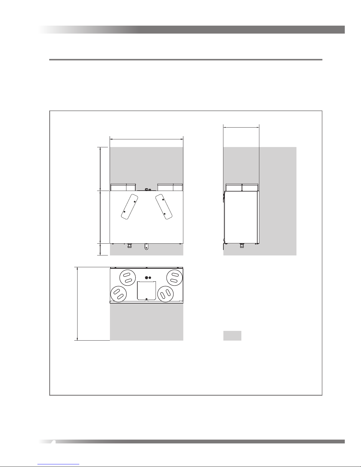
Dimensions HRV1.25 Q Plus
This diagram details the overall size of the unit and the additional space required
around the unit to allow for commissioning and future servicing and maintenance.
430
295
600
715
600
300
100
Service Void
DO NOT
‘BOX-IN’ UNIT
DO NOT
‘BOX-IN’ UNIT
All dimensions in millimetres
5
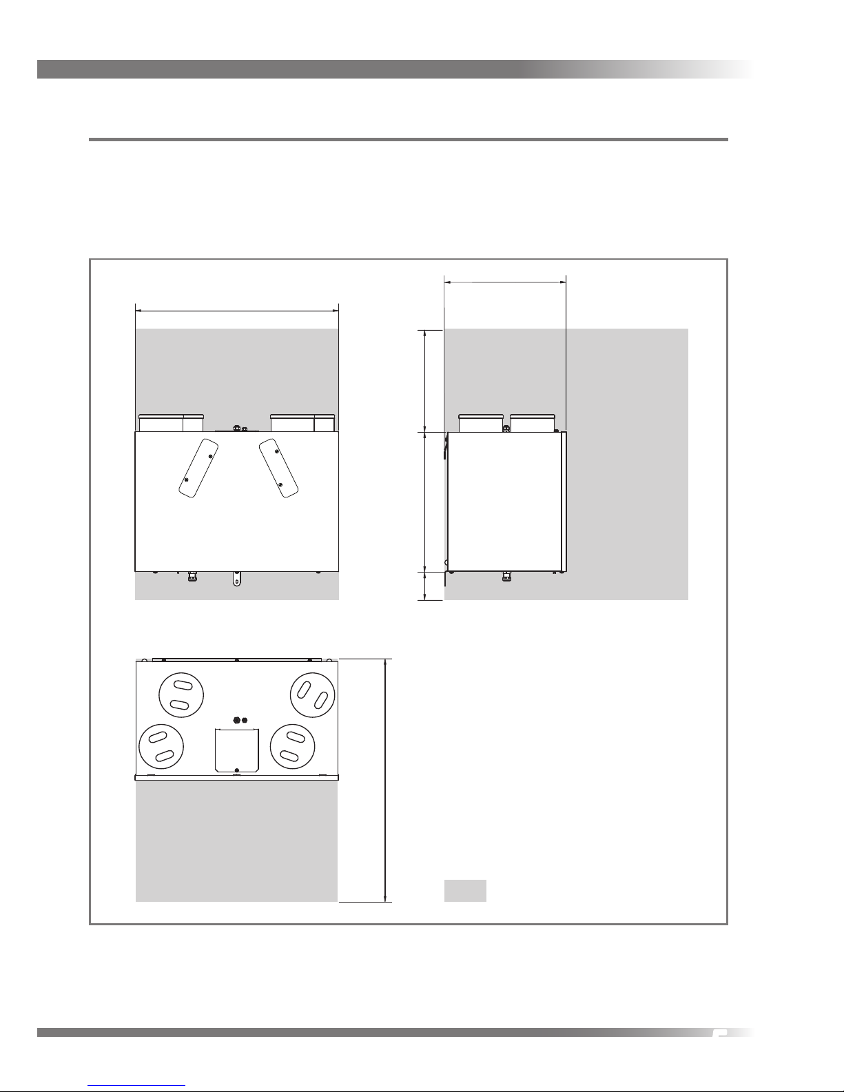
Dimensions HRV1.75, 2 & 3 Q Plus
This diagram details the overall sizes of the units and the additional space required
around the units to allow for commissioning and future servicing and maintenance.
426
490
715
860
100
Service Void
300
DO NOT
‘BOX-IN’ UNIT
All dimensions in millimetres

6
Product Features
The table below lists the models covered by this Product Manual. To nd out what
features your Titon HRV Q Plus has refer to the part number. The part number can
be found on the serial number label xed to the top and front of the unit.
Model
Part
Number
auralite® Connection
Filter Covers
Auto Setback Speed
Continuous Speed
Boost Speed with Overrun Timer
Summer Bypass
Summer Mode
Ø100 & 125mm Ducting
Ø125 & 150mm Ducting
Independent Adjustment of Fans
Step-less Fan Speed Adjustment
Automatic Frost Protection
HRV1.25 Q Plus TP406MB
HRV1.75 Q Plus TP404MB
HRV2 Q Plus TP401MB
HRV3 Q Plus TP402MB
GB Patent Nos.
GB2469254, GB2470331, GB2470528, GB2470684 GB2491516, & GB2471406
EP Patent Application No.
EP2242959

7
Controls & Features
The HRV Q Plus units are controllable by various volt free switches and sensors.
The following describes the controls and features of the HRV Q Plus units and how
they are controlled. Refer to the table opposite. Ensure all controls are adequately
labelled, indicating their function clearly.
auralite
®
auralite® is a low voltage hard wired remote LED ventilation system status indicator,
designed to t a standard UK patress or recessed backbox. The indicator has six
LEDs which display:-
y Normal Solid light - Unit is running at Continuous Speed.
Flashing light - Unit is running at Setback Speed.
y Frost Unit is in Automatic Frost Protection mode.
y Filter Filters require change.
y Boost Solid light - Unit is running at Boost Speed.
Flashing light Boost Alert is active.
y Summer Unit is in Summer bypass.
y Fault Unit has a fault - Contact the installer.
Ventilation
System
auralite® Indicator Panel

8
Filter Covers
The units are tted with removable lter covers on the front panel.
Auto Setback Speed
Setback Speed is used to reduce ventilation rates. Setback Speed is automatically
set at the mid point between minimum possible Continuous Speed and the
selected Continuous Speed. The Setback Speed can be enabled by connection of a
volt free one-way switch, or combined with the Boost Speed with the 3 position
switch TP 508.
Continuous Speed
Continuous Speed is the normal continuous extract and supply air ow running
speed of the units.
Boost Speed with Overrun Timer
Boost Speed increases the extract and supply air ow. Boost Speed is congured
with Step-less independent fan controls and includes an Overrun Timer variable
between 0 and 60 minutes. The Boost Speed can be triggered by any device which
provides a volt free one-way switch, such as a PIR, thermostat, humidistat or a
standard one-way switch.
auralite® Boost Alert
Boost Alert is a timer designed to prevent the HRV being inadvertently left in Boost
for long periods of time. Once the HRV is placed in Boost the timer is started and
after 2 hours Boost Alert will be activated. This is indicated by the Boost LED on the
auralite® Indicator Panel ashing. Once Boost Alert has been activated the Overrun
Timer is disabled meaning the HRV will return to Continuous Speed as soon as the
switch holding the unit in Boost is released.

9
Summer Bypass
Summer Bypass is designed to operate during hot periods where fresh air can be
vented straight into the property without being preheated by the extracted stale
air. Summer Bypass operation is automatically controlled. The Summer Bypass
mechanism diverts the stale air being extracted from the dwelling around the heat
cell so that its heat energy is not transferred to the fresh air being supplied to the
property.
Automatic Frost Protection
During very cold weather, Automatic Frost Protection will detect temperatures that
could form ice inside the unit. It will reduce the supply ventilation rate to prevent
ice build up within the heat cell. Automatic Frost Protection reduces the ow rate of
cold air, thus allowing the warmer stale air to raise the temperature within the heat
cell to such a level that prevents the formation of ice. As internal temperatures rise
Automatic Frost Protection will increase the supply ventilation ow rate back to the
commissioned settings.
Summer Mode
In properties where it is desirable to reduce the supply of warm fresh air during hot
weather, but where full Summer Bypass may be inappropriate or not available, the
optional Summer Mode operation is available. Summer Mode operates by stopping
the supply fan. Summer Mode can be triggered either manually or automatically:
Manual - This is by means of a volt-free switch wired directly into the controller PCB
Automatic - This is by means of a dedicated wall mounted room thermostat. In
this conguration Summer Mode will only operate when the temperature within
the room has exceeded the dedicated thermostat setting. When Summer Mode is
selected the supply fan will remain o even if the HRV is placed into Boost.
Summer Mode must not be installed in dwellings where open ue combustion
appliances are used. Summer Mode must not be installed on HRV Q Plus MB units.

10
Packaging Contents
Inspect the unit when taking delivery. Check the unit for damage and that all
accessories have been supplied. Each HRV Q Plus unit is supplied with:
Mounting Bracket x 2.
Safety Bracket x 1.
15mm Condensate Drain Olive & Nut x 1.
M6x10mm Pan Head screws x 4.
M6 washers x 4.
Transport Bungs x 4, supplied packed in Duct Ports.
Product Manual x 1.
User Guide x 1.
Any shortages or damage must be immediately reported to the supplier.

11
Installation
Fixing
Titon recommend the use of guidance given in the Domestic Ventilation
Compliance Guide 2010 Edition ISBN-978 1 85946 378 9 and Approved Document
Part F 2010 ISBN-978 1 85946 370 3 for all installations in the United Kingdom.
The above documents can be downloaded free from www.
planningportal.gov.uk.
Do not remove the Transport Bungs until connecting ducting. Transport Bungs are
tted to prevent debris falling into the unit and causing blockages and damage:
The Titon HRV Q Plus is designed
to be mounted on a wall or similar.
The mounting surface must be
suciently strong to support the
unit.
Consider the positioning of
electrical services and the
Condensate Drain when siting the
unit.
Ensure there is sucient access
around the HRV Q Plus for future
maintenance.
Do not ‘box-in’ the unit making
access to the unit dicult for maintenance and repair.
Transport Bungs highlighted

12
The Unit must be mounted plumb and level front to back and side to side.
1. Mark a horizontal line on the wall
using a spirit level. This line will be
approximately 95mm below the
location of the top face of the unit
when tted (excluding duct ports).
2. Use one of the Mounting Brackets
as a template to mark the three
xing hole centres.
3. Drill holes for xings, always use a
xing suited to the wall type.
4. Fix one Mounting Bracket to the
wall ensuring the interlocking side
is at the top, as shown.
Mounting Bracket highlighted

13
5. Fix the remaining Mounting
Bracket to the unit using the M6
screws and washers provided,
ensuring the interlock side is at the
bottom. Do not overtighten.
6. Mount the unit by locating the
two Mounting Brackets together.
Ensure a positive location is made
between the two Mounting Bracket
7. The Safety Bracket MUST be tted.
Fix the lower Safety Bracket as
shown using the remaining M6
screw, washer and suitable wall
xing. Packing to be used as
required behind the Safety Bracket
to ensure unit is level.
Hook onto
wall bracket
Safety Bracket highlighted

14
Condensate Drain
The unit’s Condensation Drain Pipe must be tted and connected to the dwelling’s
foul water drainage system in accordance with the relevant building regulations.
The Condensation Drain Pipe:
Is attached via a 15mm
compression tting (drain pipe
shown un-insulated for clarity), on
the base of the unit.
Must incorporate a suitable trap,
which must act as an air lock.
Must be adequately secured and be
insulated with the equivalent of at
least 25mm of insulating material
with a thermal conductivity of
0.04 W/(mK) if any part of the pipe
passes though an unheated void.
Should be installed to have a
minimum 5° fall from the unit.
Titon recommend the use of
diaphragm type waste valve in
place of a conventional ‘wet’ trap
which could dry out. Such as, BRE
certicate no. 042/97 ‘Hepworth
Hepv0 Hygienic self sealing plastic
waste valve’ recommended as an
alternative to traditional U-Traps.

15
Ducting Connections
Titon recommend the use of guidance given in the Domestic Ventilation
Compliance Guide 2010 Edition ISBN-978 1 85946 378 9 and Approved Document
Part F 2010 ISBN-978 1 85946 370 3 for all installations in the United Kingdom.
The above documents can be downloaded free from www.
planningportal.gov.uk
Once the unit has been installed and the ducting is ready to connect to the unit,
remove the Transport Bungs from the Duct Ports.
Titon recommend that:
1. Ø125mm ducting is used to connect the HRV1.25 Q Plus.
2. Ø150mm ducting is used to connect the HRV1.75, 2 & 3 Q Plus.
3. A short piece of exible ducting, approximately 200mm long is used to
connect the unit to the ducting system.
4. Any exible ducting used must be pulled taught.
5. A minimum distance of 200mm between the HRV Q Plus unit and any sharp
bends in duct work.
ENSURE DUCTING IS CONNECTED TO THE CORRECT PORTS
Extract from dwelling
Supply to dwelling
From atmosphere
To atmosphere
240V. AC
ENSURE DUCTING IS CONNECTED TO
THE CORRECT PORTS
Extract from dwelling
Supply to dwelling
From atmosphere
To atmosphere
front

16
6. Ducting should be insulated where it passes through unheated areas and
voids with the equivalent of at least 25 mm of a material having a thermal
conductivity of ≤0.04 W/(m.K) to reduce the possibility of condensation
forming. Where a duct extends externally above roof level the section above
the roof should be insulated or a condensate trap should be tted just below
roof level.
7. Ducts within the building heated envelope between the external terminals and
the unit’s From Atmosphere and To Atmosphere ports should be insulated and
wrapped additionally with a vapour barrier outside the insulation.
8. Where ducts pass through re barriers, they must be appropriately re stopped
in accordance with the requirements of Part B of the Building Regulations (for
England & Wales).
9. A ducting condensate drain must be tted to vertical To Atmosphere duct
work.
10. Ducting must be installed in such a way that resistance to airow is minimised.
11. Ducting connected to the From Atmosphere & To Atmosphere ports, must be
to the external air outside the building envelope.
12. All ducting joints including those to the HRV Q Plus unit’s Duct Ports must be
permanently sealed with tape and/or an appropriate non-hardening sealant
and/or Jubilee clips or similar. Do not distort ducting or Duct Ports by over
tightening clips.
13. A minimum distance of 2m exists between the external supply and exhaust
terminals.

17
Wiring & Safety
WARNING: The unit MUST be earthed. All wiring must conform to current I.E.E.
Wiring Regulations and all applicable standards and Building Regulations.
1. Electrical installation of the appliance MUST be carried out by a suitably
qualied competent person.
2. The unit is supplied with a mains rated 3 core exible cord (PVC sheathed,
brown, blue and green/yellow 0.75mm²).
3. Inspect the appliance and electrical supply cord. If the supply cord is damaged,
it must be replaced by the manufacturer, their service agent or similarly
qualied persons in order to avoid a hazard.
4. The appliance must be connected to a local double pole isolation switch with a
contact separation of at least 3mm.
5. HRV1.25 Q Plus, HRV1.75 Q Plus, & HRV2 Q Plus are suitable for 230V ~ 50/60Hz
single phase with a fuse rating of 3A.
6. HRV3 Q Plus suitable for 230V ~ 50/60Hz single phase with a fuse rating of 5A.
7. auralite®, control & communication cable access is via the tted cable gland(s)
which are suitable for Ø3- 6mm cable.
8. auralite® Communication Cable - Unshielded 4 Core 18-24AWG Stranded,
Tinned Copper.
9. Communication cable should not be placed within 50mm or on the same
metal cable tray as 230V switched live, lighting or power cables and any cables
not intended for use with a HRV.
10. Ensure all cable glands are fully tightened.
Wiring Connections Access
Access to the connections for auralite®, Boost and other volt free control functions
is via the hinged cover on the top of the unit, at the front. For access for service and
maintainance remove the whole cover.

18
auralite® Wiring Diagrams
0V
12V
A
B
0V
12V
A
B
auralite® connection at Indicator
auralite® connection at Unit
0V
12V
A
B
19
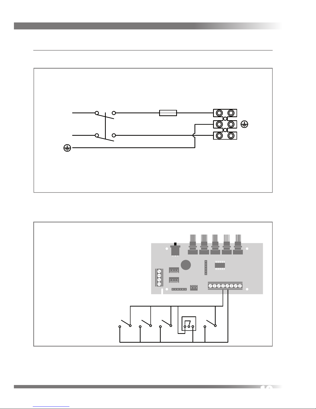
Wiring Diagrams
Double Pole Isolator Fuse
L
N
L
N
Supply wiring diagram 230V~50Hz ref EE 141
Volt-free boost switching of MVHR
controller PCB using single-pole
switches TP 502, TP 503, TP 507
and / or TP500 / TP501 humidistat.
There is no limit to the number of
single pole switches or
humidistats that can used.
Volt-free setback switching of MVHR
controller PCB using single-pole
latching switch and / or volt-free
normally open relay contacts.
To avoid the unit being inadvertently
left in Setback Mode, it is recom-
mended that only one latching switch
is tted.
TP500/TP501
Humidistat
1
2 3
Boost switching and Humidistat connection

20
Wiring Diagrams
Three Position Rotary Switch TP 508 switching and connection
Volt-free boost switching of MVHR
controller PCB using single-pole
switches TP 502, TP 503, TP 507
and / or TP500 / TP501 humidistat.
There is no limit to the number of
single pole switches or
humidistats that can used.
SWITCH POSITIONS
1 - Setback Speed
2 - Continuous Speed
3 - Boost Speed
L U1 U2 U3
TP 508
Three position rotary switch
Setback Mode switching and connection
Volt-free setback switching of MVHR
controller PCB using single-pole
latching switch and / or volt-free
normally open relay contacts.
To avoid the unit being inadvertently
left in Setback Mode, it is recommended that only one latching switch
is tted.
Volt-free setback switch or
normally open relay contacts
Volt-free activation of Summer Mode
using one way latching switch.
Not to be installed
on MB models.

21
Wiring Diagrams

22
Notes

23
Commissioning
Controls
The fan speeds of the Titon HRV Q Plus will require adjustment to ensure the ow
rates achieved provide adequate ventilation. The Titon HRV Q Plus has 2 standard
fan speed settings Continuous Speed and Boost Speed.
The Continuous Speed and Boost Speed are programmed by placing the controller
into Program Mode via the Program/Run Switch and changing the position of rotary
potentiometers.
When applying power for the rst time, the unit can take up to four minutes to start
operating.
Prior to the rst commission set Continuous Speed potentiometers to minimum
and Boost Speed potentiometers to maximum or reset the controller.
Control Parameters
The Boost Speed cannot be set lower than the Continuous Speed.
The Continuous Speed cannot be set higher than the Boost Speed.
All switching inputs are disabled when the Program/Run Switch is in
Continuous or Boost positions.
Speed control potentiometers are disabled when the Program/Run switch is in
centre Run position.
Boost
Overrun
Timer
Program
Switch
Run
Continuous
Boost
Boost Overrun Timer
Extract
Supply
Potentiometers
Extract
Supply
BP 40262/099
BoostCont
Control Identication
Run
Continuous
Boost
Boost Overrun Timer
Extract
Supply

24
For the commissioning settings to be stored the unit needs to be powered up.
Continuous Supply & Extract Speeds:
1. Move Program/Run Switch to
Continuous position.
2. Rotate supply fan Continuous
Speed adjustment potentiometer
to achieve required supply
continuous air ow.
3. Rotate extract fan Continuous
Speed adjustment potentiometer
to achieve required extract
continuous air ow.
4. Return Program/Run Switch
to centre position to exit
commissioning.
Boost Supply & Extract Speeds:
1. Move Program/ Run Switch to Boost position.
2. Rotate supply fan Boost Speed adjustment potentiometer to achieve required
supply boost air ow.
3. Rotate extract fan Boost Speed adjustment potentiometer to achieve required
extract boost air ow.
4. Return Program/Run Switch to centre position to exit commissioning.
Boost Overrun
Boost Overrun Timer is variable between
0 and 60 minutes. Rotate potentiometer
to change overrun time. This can be
done at any time.
Run
Continuous
Boost
Boost Overrun Timer
Extract
Supply
1
2
3
4
5
6
7
8
Commissioning Pot positions
Boost
Overrun
Timer
Program
Switch
Run
Continuous
Boost
Boost Overrun Timer
Extract
Supply
Potentiometers
ExtractSupply
BoostCont
1
2
3
4
5
6
7
8
0
60
30

25
Controller Reset
Following a controller reset the ventilation system will need to be
fully commissioned.
The procedure to reset the Titon HRV Q Plus controller is a simple three step
operation. The unit will need to be powered up during the reset procedure.
1. Rotate the Supply and Extract Continuous Speed potentiometers fully anticlockwise.
2. Rotate Supply and Extract Boost Speed potentiometers fully clockwise move
the Run/Program Switch from the Run position to the Continuous position,
from the Continuous position to the Boost position and back to the Run
position. To ensure that the reset switch movements are registered by the
controller wait two seconds between each switch movement. Controller reset
is now complete.
Hardware Reset
Certain conditions (repeated supply interruptions etc.) can activate the automatic
motor protection mode. Whereby the fan motors are prevented from operating.
This requires a hardware reset to return the unit to normal operating mode, to
achieve this power to the unit should be switched o for 5 minutes, restoring
the power after this time will reset the hardware of both the motor and PCB.
Commissioning settings are not aected during a hardware reset.

26
Maintenance
All ventilation units require periodic maintenance. Routine maintenance, apart
from lter changes, must only be carried out by a suitably qualied and competent
person.
WARNING: The unit uses a 230V ~ supply and contains rotating mechanical
parts. ISOLATE the unit from mains power supply and allow sucient time for
all moving parts to stop before undergoing any Servicing or Maintenance.
Filter Replacement
Filters should be replaced at least annually, or more regularly dependent on
environmental conditions.
The auralite® Indicator Panel will display a lter notication after 6 months of use. If
lter maintenance is being done less frequently the notication can be reset.
Replacement Filters are available from Titon. Titon HRV Q Plus Filters are available in
two grades G3 and G4. Filter media should be replaced like for like.
Filter Part numbers in table below. The Unit part number can be found on the serial
number label xed to the top and front of the unit.
G3 Filters - Both faces white.
G4 Filters - One face white, one face blue.
Model Part Number
G3 Filter Set
2 framed lters
G4 Filters Set
2 framed lters
HRV1.25 Q Plus TP406MB XP40032/099 XP46022/099
HRV1.75 Q Plus TP404MB
XP40133/099 XP46133/099
HRV2 Q Plus TP401MB
HRV3 Q Plus TP402MB

27
How to Change Filters
1. Remove Filter Covers by undoing
the four screws.
2. Slide out Filters.
3. Filters can be cleaned by carefully
using a vacuum cleaner, Filters
should be replaced at least
annually.
4. MB models (excluding the HRV1.25
Q Plus) use unequal Filters. When
replacing Filters ensure the lter
with the open section is tted into
the right hand opening and in the
correct orientation, see illustration.
5. Replace Filters by carefully sliding
the replacement/cleaned lters.
6. Replace the Filter Covers. Do not
overtighten screws.
auralite® Filter Notication Reset
Ensure the HRV is powered up. To clear the auralite® lter notication press &
hold the reset switch with a ball point pen or similar object for 10 second. The
switch is located behind the small hole in the front of the auralite®. All lights will
momentarily be illuminated indicating a successful reset.

28
Front Cover Removal
1. ISOLATE the unit from mains power
supply and allow sucient time for
all moving parts to stop.
2. Loosen the two corner screws
located on the bottom front of the
unit.
3. Completely remove the centre
screw.
4. Completely remove the Front
Cover by pulling it away from the
unit at the bottom and lifting.
Cover replacement is the reverse of
the above steps. Ensure it is securely
located at the top before tightening
screws.
Cleaning Interior
For best results:
1. Slide out Filter Frames tted either side of heat exchanger.
2. Carefully remove any dust from face of heat exchanger, interior of the unit and
the Bypass(if tted) using a vacuum cleaner.
3. Do not use water or any other uids.
Cleaning Exterior
For best results use a clean cloth and warm water with a mild detergent solution.
Do not use solvents or abrasive cleaners.
100mm MAX
1
2

29
Condensate Tray
If the Condensate Tray is split a replacement must be ordered and tted.
HRV 1.25 Q Plus Part No. XP40042/012
HRV1.75, 2 & 3 Q Plus Part No. XP40142/012
Condensate Tray

30
Service Record
Serviced By Company Date Notes

31
Serviced By Company Date Notes

MARKETING DIVISION
International House, Peartree Road, Stanway, Colchester, Essex CO3 0JL
Tel : +44 (0) 1206 713800 Fax : +44 (0) 1206 543126
Email : ventsales@titon.co.uk Web: www.titon.com
DO 5168 issue 04
©2013 TITON
In the event of any queries please contact the system installer. Ensure this
booklet is passed to the householder once installation and commissioning of
the ventilation system is complete. This Product Manual must be kept in the
Home Information Pack and used as a service record.
Installed by
 Loading...