


ventilation systems
Extract Ventilation Unit
Product Manual
EN
CME1 Q Plus
TP300A
TP301A
CME1 Q Plus
with Humidity Sensor
TP300HA
TP301HA

2
Product Overview
Safety and Guidance . . . . . . . . . . . . . . . . . . . . . . . . . 3
Dimensions. . . . . . . . . . . . . . . . . . . . . . . . . . . . . . . . . 4
Component Identication . . . . . . . . . . . . . . . . . . . . 5
Packaging Contents. . . . . . . . . . . . . . . . . . . . . . . . . . 6
Product Features . . . . . . . . . . . . . . . . . . . . . . . . . . . . 7
Auto Setback Speed . . . . . . . . . . . . . . . . . . . . 8
Setback Speed . . . . . . . . . . . . . . . . . . . . . . . . . 8
Continuous Speed . . . . . . . . . . . . . . . . . . . . . . 8
Boost Speed with Overrun Timer. . . . . . . . . . 8
Boost Overrun Timer . . . . . . . . . . . . . . . . . . . . 8
Integrated Humidity Sensor. . . . . . . . . . . . . . 8
Installation
Fixing . . . . . . . . . . . . . . . . . . . . . . . . . . . . . . . . . . . . . 9
Ducting Connections. . . . . . . . . . . . . . . . . . . . . . . . 11
How to Convert Port Cover . . . . . . . . . . . . . . 13
Wiring & Safety . . . . . . . . . . . . . . . . . . . . . . . . . . . . 14
Wiring Connections Access. . . . . . . . . . . . . . 14
Wiring Diagrams . . . . . . . . . . . . . . . . . . . . . . 15
Wiring Diagrams . . . . . . . . . . . . . . . . . . . . . . 16
Commissioning
TP300A & 301A . . . . . . . . . . . . . . . . . . . . . . . . . . . . .17
Control Parameters . . . . . . . . . . . . . . . . . . . . .17
Commissioning. . . . . . . . . . . . . . . . . . . . . . . . .18
Boost Overrun. . . . . . . . . . . . . . . . . . . . . . . . . .19
Controller Reset . . . . . . . . . . . . . . . . . . . . . . . .19
Hardware Reset . . . . . . . . . . . . . . . . . . . . . . . . 19
TP300HA & TP301HA. . . . . . . . . . . . . . . . . . . . . . . . . 20
Control Parameters . . . . . . . . . . . . . . . . . . . . .20
Commissioning. . . . . . . . . . . . . . . . . . . . . . . . .21
Boost Overrun . . . . . . . . . . . . . . . . . . . . . . . . . 22
Humidity Sensor . . . . . . . . . . . . . . . . . . . . . . . 22
Controller Reset . . . . . . . . . . . . . . . . . . . . . . . .23
Hardware Reset . . . . . . . . . . . . . . . . . . . . . . . . 23
Maintenance
Routine maintenance . . . . . . . . . . . . . . . . . . . . . . . .24
Cleaning Exterior . . . . . . . . . . . . . . . . . . . . . . .24
Cleaning Interior . . . . . . . . . . . . . . . . . . . . . . .24
Access to the Interior for Cleaning . . . . . . . .25
Service Record . . . . . . . . . . . . . . . . . . . . . . . . . . . . . . 27

IMPORTANT - Fully read this Product Manual to help ensure the ventilation
system is installed, commissioned and used properly
3
Product Overview
Safety and Guidance
Important: read these instructions fully before the installation of this appliance
1. Installation of the appliance must be carried out by a qualied and suitably
competent person and be carried out in clean, dry conditions where dust and
humidity are at minimal levels.
2. The unit must be stored in a clean and dry environment.
3. Do not install the appliance in areas where the following may be present or
occur:
x Excessive oil or a grease laden atmosphere.
x Corrosive or ammable gases, liquids or vapours.
x Ambient temperatures above 40°C or below -5°C.
x Humidity levels above 90% or in a wet environment.
x The appliance is not suitable for installation to the exterior of the dwelling
4. This appliance is not intended for use by persons (including children) with
reduced physical, sensory or mental capabilities, or lack of experience and
knowledge, unless they have been given supervision or instruction concerning
use of the appliance by a person responsible for their safety.
5. Children should be supervised to ensure that they do not play with the
appliance.
6. Ensure that external grilles are located away from any ue outlet, in accordance
with relevant Building Regulations.
7. The unit must not be connected to a tumble drier.
8. The unit must not be connected to a cooker hood.
9. Precautions must be taken to avoid the back-ow of gases into the room from
an open ue appliance.
10. Ensure all ducting is free from debris and blockages before switching on the
unit.

4
Dimensions
This diagram details the overall size of the unit and the additional space required
around the unit to allow for commissioning and future servicing and maintenance.
450
421
355
390
252
550
450
590
Service Void
All dimensions in mm

5
Component Identication
Unit components
Cover
Inlet ring
Scroll
Base
Cover / Scroll / Inlet Ring assembly

6
Packaging Contents
Inspect the unit when taking delivery. Check the unit for damage and that all
accessories have been supplied. The box contains:
CME1 Q Plus Unit x 1.
Port covers x 3.
This Product manual x 1.
Screw Pack x 1.
User Guide x 1.
All shortages or damage must be immediately reported to the supplier.

7
Product Features
Compact low prole unit.
Hidden installation xings.
All duct ports on one level.
Accepts 204mm x 60mm or 110mm x 54mm ducting.
Can be cleaned and serviced without disturbing any ducting.
Straightforward installation.
Versatile volt-free boost and setback switching.
The CME1 Q Plus is controllable by various volt-free switches and sensors. Mains
switching can be achieved by use of the Titon Boxed Relay 5A TP 505.
The following describes the controls and features of the CME1 Q Plus and how they
are controlled. Ensure all controls are adequately labelled, indicating their function
clearly.
Model CME1 Q Plus
Part Number TP300A TP301A TP300HA TP301HA
Complete unit
l
l
2nd Fix Cover / Scroll / Inlet Ring assembly
l l
Auto Setback Speed
l
l
Setback Speed
l l
Continuous Speed
l
Boost Speed
l
Boost Overrun Timer
l
Integrated Humidity Sensor
l l
GB Patent Application No. GB2491516,
EP Patent Application No. EP2242959

8
Auto Setback Speed
Setback Speed is a reduced ventilation rate. Auto Setback Speed is automatically
set at the mid point between minimum possible Continuous Speed and the
selected Continuous Speed. The Auto Setback Speed can be enabled by
connection of a volt-free one-way switch, or combined with the Boost Speed with
the 3 position switch TP 508.
Setback Speed
Setback Speed is a reduced ventilation rate. Setback Speed is congured using
a step-less independent fan control potentiometer. The Setback Speed can be
enabled by connection of a volt-free one-way switch, or combined with the Boost
Speed with the 3 position switch TP 508.
Continuous Speed
Continuous Speed is the normal running speed of the unit. Continuous Speed is
congured using a step-less independent fan control potentiometer.
Boost Speed with Overrun Timer
Boost Speed is an increased speed providing higher extract air ow. Boost Speed
is congured using a step-less independent fan control potentiometer. The Boost
Speed can be triggered by any device which provides a volt-free one-way switch,
such as a PIR, thermostat, humidistat or a standard one-way switch
Boost Overrun Timer
Boost Overrun Timer maintains the Boost Speed for a specic time variable between
0 and 30 minutes. The Boost Overrun Timer time is congured using step-less
independent potentiometer.
Integrated Humidity Sensor
Some units are tted with an Integrated Humidity Sensor. This continuously
monitors the relative humidity (RH) of the extracted air and triggers Boost Speed
when the relative humidity rises over the set threshold. The Humidity Sensor’s
trigger point is variable from 55%RH to 85%RH and is congured using step-less
independent potentiometer.

9
Installation
Fixing
1. The unit must be securely xed to a
smooth at surface, any orientation
is possible.
2. Mark the four xing hole centres
using the Base as a template.
3. Drill holes for xings, use 4mm
Pan Head screws. Always use a
xing type and length suited to
the substrate type. The unit weighs
approximately 5kg.
4. Mount the Base, ensuring it is not
distorted by the xings or mounting
surface.
5. Clip the Motor and Lid assembly to
the Base, ensure that all 6 clips have
engaged.
Tighten screws by hand, DO NOT over
tighten screws or use power tools.
1
2
3
4
5
6
260
260
EXTRACT
PORT
Positions of Clips

10
6. Unscrew the 2 retaining screws that hold on the Cover and remove, retain the
screws.
7. Fit two screws from the Screw Pack
through the preformed holes at the
front of the Inlet Ring to securely x
the Inlet Ring/Scroll assembly to the
Base.
8. Fit one screw from the Screw Pack
through the preformed hole in the
back of the Base. to securely x the
Inlet Ring/Scroll assembly to the
Base.
9. Re-t the Cover using the 2 screws
retained and 1 screw from the
Screw Pack.

11
Ducting Connections
Titon recommend the use of guidance given in the Domestic Ventilation
Compliance Guide 2010 Edition ISBN-978 1 85946 378 9 and
Approved Document Part F 2010 ISBN-978 1 85946 370 3 for all
installations in the United Kingdom.
The above documents can be downloaded free from www.planningportal.gov.uk.
Titon recommend that:
1. 204 x 60mm ducting is used for the
connection of the Extract Port to
Outside.
2. 204 x 60mm or 110 x 54mm ducting
is used for connection to the other
ports.
3. A minimum distance of 200mm
between the CME1 Q Plus unit and
any sharp bends in duct work.
4. Ducting should be insulated where
it passes through unheated areas
and voids.
5. Unit should be insulated when
tted in unheated area.
6. Where a duct extends externally above roof level the section above the roof
should be insulated or a condensate trap should be tted just below roof level.
7. Where ducts pass through re barriers, they must be appropriately re stopped
in accordance with the requirements of Part B Building Regulations (England &
Wales).
8. A ducting condensate drain must be tted to vertical Extract Port to Outside
duct work.
9. Condensate drain pipe work must be adequately secured, installed to have
a minimum 5° fall and be insulated if any part of the pipe passes though an
unheated void.
EXTRACT
PORT
Extract Port to Outside

12
10. All insulation to be the equivalent of
at least 25mm of insulating material
with a thermal conductivity
of 0.04 W/(mK).
11. Ducting must be installed in such
a way that resistance to airow is
minimised.
12. Ducting connected to the Extract
Port to Outside must be to the
external air outside the building
envelope.
13. All ducting joints including those
to the CME1 Q Plus unit’s Duct Ports
and Convertible Port Covers must
be permanently connected and
sealed.
14. Do not distort ducting, Convertible
Port Cover or Duct Ports.
15. 204 x 60mm ducting ts inside the
units Duct Ports.
16. 110 x 54mm ducting ts inside the
Convertible Port Cover.
17. Unused extract ports must be tted
with non-converted or undamaged
port covers.

13
How to Convert Port Cover
1. To enable tment of 110 x 54mm
ducting, modify the Convertible
Port Cover by tearing out the ‘rip
strip’.
2. When using the convertible port
cover ensure the tear out section is
completely removed.

14
Wiring & Safety
WARNING: The unit MUST be earthed. All wiring must conform to current I.E.E.
Wiring Regulations and all applicable standards and Building Regulations.
1. Electrical installation of the appliance MUST be carried out by a suitably
qualied competent person.
2. Inspect the appliance. If damaged, it must be replaced by the manufacturer,
their service agent or similarly qualied persons in order to avoid a hazard.
3. The appliance must be connected to a local double pole isolation switch with a
contact separation of at least 3mm. Ideally located adjacent to the unit.
4. CME1 Q Plus is suitable for 230V ~ 50/60Hz single phase with a fuse
rating of 3A.
5. Mains switching can be achieved by use of the Titon Boxed Relay 5A TP 505
Wiring Connections Access
Access to the connections for mains, boost and other volt-free control functions
is via removal of the Cover. Cables must be routed as shown and secured with
clamps provided.
Internal Cable Routing
Cable Access

15
Wiring Diagrams
Double Pole Isolator 3A Fuse
L
N
L
N
Supply Wiring Diagram 230V~50/60Hz EE 141
Volt-free boost switching of unit’s
controller PCB using single-pole
switches TP 502, TP 503, TP 507
and/or TP500 / TP501 Humidistat.
There is no limit to the number of
single pole switches or
humidistats that can used.
TP500 / TP501
1 2 3
Boost switching and External Humidistat connection ref EE 151
16
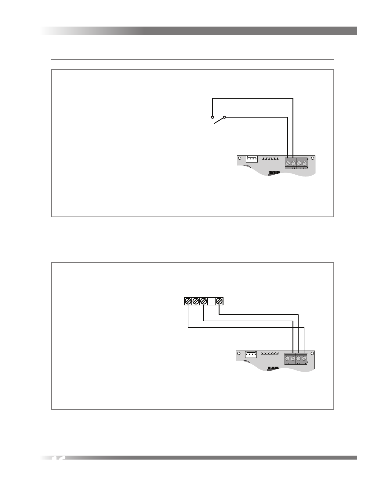
Wiring Diagrams
Volt-free setback switching of the unit’s
controller PCB using single-pole
latching switch and / or volt-free
normally open relay contacts.
To avoid the unit being inadvertently
left in Setback Mode, it is recommended that only one latching switch
is tted.
Volt-free setback switch or
normally open relay contacts
Setback Switch connection ref EE 152
Three position Rotary Switch TP 508 switching and connection ref EE 153
SWITCH POSITIONS
1 - Setback Speed
2 - Continous Speed
3 - Boost Speed
LU1U2U3
TP 508
Three position rotary switch

17
Commissioning
TP300A & 301A
The fan speeds of the Titon CME1 Q Plus will require adjustment to ensure that the
ow rates achieved provide adequate ventilation. The Titon CME1 Q Plus has 3
standard fan speed settings, Continuous Speed, Boost Speed and Setback Speed.
The Continuous Speed and Boost Speeds are adjustable via Rotary Potentiometers.
Setback Speed is automatically set at the mid point between minimum possible
Continuous Speed and the selected Continuous Speed.
Prior to the rst commission, set the Continuous Speed potentiometer to minimum
by rotating fully anti-clockwise and set the Boost Speed potentiometer to maximum
by rotating fully clockwise.
Control Parameters
All volt-free switch inputs are disabled when the Program / Run Header Link is
in the Program position.
All speed control potentiometers are disabled when the Program / Run Header
Link is in the Run position.
The unit needs to be powered up for the commissioning settings to be stored.
Continuous Speed
Boost Speed
Boost Overrun Timer
Program / Run Header Link
Continuous Speed
Boost Speed
Boost Overrun Timer
Control Identication

18
Commissioning
1. Remove Program / Run Header Link
and place in the Program Position,
tted over both pins. The CME1
Q Plus will automatically switch
between Continuous Speed and
Boost Speed when adjusting the
respective potentiometer.
2. Rotate Continuous Speed
adjustment potentiometer to
achieve required continuous air
ow.
3. Rotate Boost Speed adjustment
potentiometer to achieve required
boost air ow.
4. Return Program / Run Header Link
to Run Position, tted to one pin, to
exit commissioning.
After commissioning the Program / Run
Header Link must be placed in the
Run position.
Alternatively the Program / Run Header
Link can be completely removed to
‘lock’ the commissioned settings.
Header Link in Program position
Header Link in Run positions
Run
Continuous
Boost
Boost Overrun Timer
Extract
Supply
1
2
3
4
5
6
7
8
Commissioning Pot positions

19
Boost Overrun
Boost Overrun Timer is variable between
0 and 30 minutes. Rotate potentiometer
to change overrun time. Boost Overrun
Timer adjustment can be done at any
time without the need to move the
Program / Run Header Link.
Controller Reset
Following a controller reset the ventilation system will need to be fully recommissioned. The unit will need to be powered up during the reset procedure.
1. Place the Program / Run Header Link in the Run Position
2. Rotate the Continuous Speed and Boost Speed adjustment fully clockwise.
3. Place Program / Run Header Link in the Program Position.
4. Rotate the Continuous Speed adjustment potentiometer fully anti clockwise.
Hardware Reset
Certain conditions (repeated supply interruptions etc.) can activate the automatic
motor protection mode. Where by the fan motors are prevented from operating.
This requires a hardware reset to return the unit to normal operating mode, to
achieve this power to the unit should be switched o for 5 minutes, restoring
the power after this time will reset the hardware of both the motor and PCB.
Commissioning settings are not aected during a hardware reset.
Boost Overrun Pot positions
Boost
Overrun
Timer
Program
Switch
Run
Continuous
Boost
Boost Overrun Timer
Extract
Supply
Potentiometers
ExtractSupply
BoostCont
1
2
3
4
5
6
7
8
0
30
15

20
TP300HA & TP301HA
The fan speeds of the Titon CME1 Q Plus will require adjustment to ensure that the
ow rates achieved provide adequate ventilation. The Titon CME1 Q Plus has 3
standard fan speed settings, Continuous Speed, Boost Speed and Setback Speed.
All speeds are adjustable via Rotary Potentiometers.
Control Parameters
All volt-free switch inputs are disabled when the Program / Run Header Link is
in the Program position.
All speed control potentiometers are disabled when the Program / Run Header
Link is in the Run position.
Boost Overrun Timer & Humidity Sensor adjustment can be done at any time
without the need to move the Program / Run Header Link
The unit needs to be powered up for the commissioning settings to be stored.
Program / Run
Header Link
Continuous Speed
Boost Speed
Humidity Sensor
Boost Overrun Timer
Setback Speed

21
Commissioning
1. Remove Program / Run Header
Link and place in the Program
Position, tted over both pins. The
CME1 Q Plus will automatically
switch between Setback Speed,
Continuous Speed and Boost Speed
when adjusting the respective
potentiometer.
2. Rotate the Speed adjustment
potentiometer to achieve required
air ow for each speed.
3. Return Program / Run Header Link
to Run Position, tted to one pin, to
exit commissioning.
After commissioning the Program / Run
Header Link must be placed in the
Run position.
Alternatively the Program / Run Header
Link can be completely removed to
‘lock’ the commissioned settings.
Header Link in Program position
Header Link in Run position
Continuous Speed
Boost Speed
Humidity Sensor
Boost Overrun Timer
Setback Speed
1
2
3
4
5
6
7
8
Commissioning Pot positions

22
Boost Overrun
Boost Overrun is variable between
0 and 30 minutes. Rotate potentiometer
to change overrun time. Boost Overrun
adjustment can be done at any time
without the need to move the Program /
Run Header Link.
Humidity Sensor
The Humidity Sensor’s trigger point is
variable from 55%RH to 85%RH. Rotate
potentiometer to change trigger point.
Humidity Sensor adjustment can be
done at any time without the need to
move the Program / Run Header Link.
Boost Overrun Pot positions
Program / Run
Header Link
1
2
3
4
0
30
15
55% 85%
70%
Humidity Sensor Pot positions
Program / Run
Header Link
1
2
3
4
5
6
7
8
55% 85%
70%

23
Controller Reset
Following a controller reset the ventilation system will need to be fully recommissioned. The unit will need to be powered up during the reset procedure.
1. Place the Program / Run Header Link in the Run Position
2. Rotate the Setback, Continuous and Boost Speed adjustment potentiometers
fully clockwise.
3. Place Program / Run Header Link in the Program Position.
4. Rotate the Setback Speed potentiometer fully anti clockwise and the
Continuous Speed adjustment potentiometer to the mid position.
Hardware Reset
Certain conditions (repeated supply interruptions etc.) can activate the automatic
motor protection mode. Where by the fan motors are prevented from operating.
This requires a hardware reset to return the unit to normal operating mode, to
achieve this power to the unit should be switched o for 5 minutes, restoring
the power after this time will reset the hardware of both the motor and PCB.
Commissioning settings are not aected during a hardware reset.

24
Maintenance
Routine maintenance
All ventilation units require periodic maintenance. Routine maintenance must
only be carried out by a suitably qualied and competent person. The CME1 Q Plus
must be periodically cleaned internally. The maximum time between cleaning will
depend on the local environment. Titon recommend the unit be cleaned every
3 – 4 years at a minimum.
In the event of any queries please contact the system installer.
WARNING: The unit uses a 230V ~ supply and contains rotating mechanical
parts. ISOLATE the unit from mains power supply and allow sucient time for
all moving parts to stop before undergoing any Servicing or Maintenance.
Cleaning Exterior
For best results use a clean cloth and warm water with a mild detergent solution.
Do not use solvents or abrasive cleaners.
Cleaning Interior
For best results use a clean damp cloth and mild detergent. Do not use solvents or
abrasive cleaners. When cleaning the interior ensure that the humidity sensor does
not get wet, dust with a dry cloth.
Humidity Sensor

25
Access to the Interior for Cleaning
To gain access to the interior of the unit
for cleaning –
1. Unscrew the 3 retaining screws that
hold on the Cover and remove
2. Remove the 4 Scroll retaining
screws.
3. Using a at bladed screw driver,
un-clip Scroll from Inlet Ring by
disengaging the 3 retaining clips.
Ensure that the Scroll is supported
and does not strain the cables.

26
4. Remove the 3 retaining screws
5. Using a at bladed screwdriver,
un-clip the Inlet Ring from Base by
disengaging the 4 retaining clips.
6. Carefully remove dust from the
unit and fan blades using a vacuum
cleaner.
7. Wipe with damp cloth and mild
detergent.
8. Check xing screws.
9. Assembly is the reverse of the
preceding instructions.
10. Ensure all fasteners are secure
before returning power to the unit.
Tighten screws by hand, DO NOT over
tighten screws or use power tools.
After servicing, always complete the
service record.
2
1
4
3
1
2
Positions of Clips

27
Service Record
Serviced by Company Name Date Notes

DO 5177 iss01 Feb 2013
MARKETING DIVISION
International House, Peartree Road , Stanway, Colchester, Essex CO3 0JL
Tel : +44 (0) 1206 713800 Fax : +44 (0) 1206 543126
Email : ventsales@titon.co.uk Web : www.titon.com
©2013 TITON
In the event of any queries please contact the system installer. Ensure this
booklet is passed to the householder once installation and commissioning of
the ventilation system is complete. This Product Manual must be kept in the
Home Information Pack and used as a Service Record.
Installed by
 Loading...