

Page 1
EN
Product Installation Manual
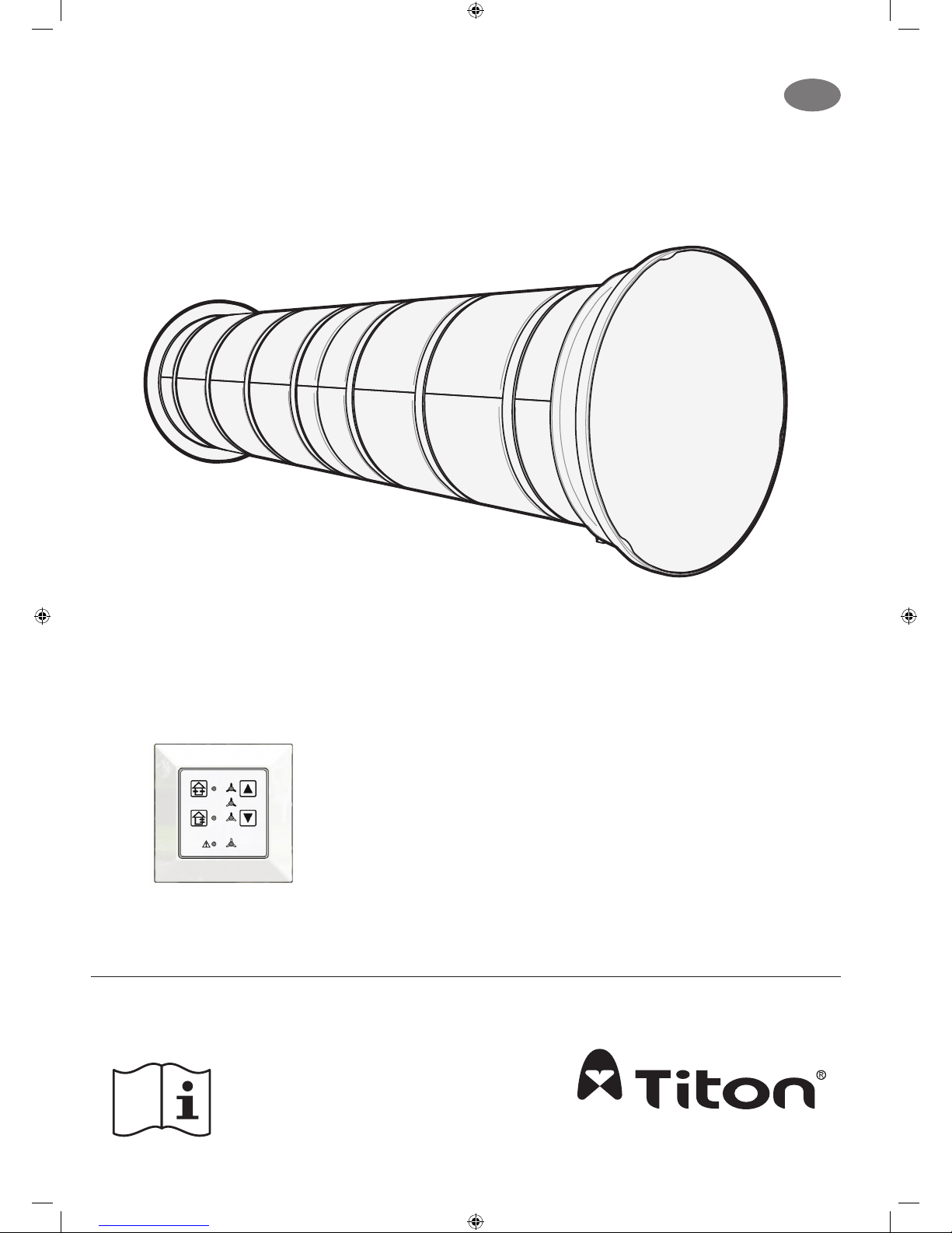
Single Room Heat Recovery Ventilation Fan Unit
ventilation systems
SR700 SRHRV Fan TP600
Single Room Heat Recovery Ventilation Controller Unit
SRC1 Controller TP590
Page 2
2
Warnings, Safety Information and Guidance
Important Information
Read these instructions fully before the installation of this appliance
1. Installation of the appliance and accessories must be carried out by a qualied and suitable
competent person and be carried out in clean, dry conditions where dust and humidity are at
minimal levels.
2. This manual covers the installation of the
Single Room Heat Recovery Ventilation
S
R700 SRHRV Fan Unit and SRC1 Controller Unit.
3. All wiring must conform to current I.E.E. Wiring Regulations and all applicable standards and
Building Regulations.
4. Inspect the appliance. If damaged, it must be replaced by the manufacturer or their service
agent in order to avoid a hazard.
5. The appliance must be connected to a local all pole isolation switch with a contact separation of
at least 3mm.
6. The
SRC1 Controller Unit is suitable for 220-240V ~ 50-60Hz single phase with a fuse
rating of 3A.
7. Control & communication cable - Titon recommends the use of unshielded CAT5e cable to
comply with EMC directives.
8. Control & communication cables should not be placed within 50mm or on the same metal cable
tray as any mains lighting or power cables.
9. The unit must be stored in a clean and dry environment.
10. Do not install the appliance in areas where the following may be present or occur:
o Excessive moisture, oil or grease laden atmosphere;
o Corrosive or ammable gases, liquids or vapours;
o Ambient temperatures above 40°C or below -5°C;
o Humidity levels above 90%;
o A wet environment.
11. The appliance is not suitable for installation to the exterior of the dwelling.
12. This appliance can be used by children aged from 8 years and above and persons with reduced
physical, sensory or mental capabilities or lack of experience and knowledge if they have been
given supervision or instruction concerning use of the appliance in a safe way and understand
the hazards involved. Children should be supervised to ensure that they do not play with the
appliance. Cleaning and user maintenance shall not be made by children without supervision.
13. Ensure that external grilles are located away from any ue outlet, in accordance with relevant
Building Regulations.
14. The unit must not be connected to a tumble dryer or a cooker hood.
15. Precautions must be taken to avoid the back-ow of gases into the room from an open ue appliance.
16. Ensure ducting is free from debris and blockages before switching on the units.
17. Before cleaning, power down the ventilation system and wait sucient time for the Fans to stop
rotating before starting cleaning.
18. When handling unit care must be taken as the unit is unbalanced.
Page 3

3
Contents
When this document is viewed
as a PDF the headings & sub
headings on this page are
hyper links to the content.
Additionally the page numbers in this
document are hyper links back to this
contents page.
Warnings, Safety Information and Guidance
Important Information . . . . . . . . . . . . . . . . . . . . . . . . . . . . . . . . . . . . . . . . . . . . . . . . . . . 2
Product Information
Benets and Features . . . . . . . . . . . . . . . . . . . . . . . . . . . . . . . . . . . . . . . . . . . . . . . . . . . . 4
Packaging Contents. . . . . . . . . . . . . . . . . . . . . . . . . . . . . . . . . . . . . . . . . . . . . . . . . . . . . . 5
SR700 Fan Unit . . . . . . . . . . . . . . . . . . . . . . . . . . . . . . . . . . . . . . . . . . . . . . . . . . . . 5
SRC1 Controller Unit . . . . . . . . . . . . . . . . . . . . . . . . . . . . . . . . . . . . . . . . . . . . . . . . 5
Dimensions & Component Identication . . . . . . . . . . . . . . . . . . . . . . . . . . . . . . . . . . . . 5
Installation
SRHRV Fan Unit . . . . . . . . . . . . . . . . . . . . . . . . . . . . . . . . . . . . . . . . . . . . . . . . . . . . . . . . . 7
Hole Preparation . . . . . . . . . . . . . . . . . . . . . . . . . . . . . . . . . . . . . . . . . . . . . . . . . . . 7
Vent Tube . . . . . . . . . . . . . . . . . . . . . . . . . . . . . . . . . . . . . . . . . . . . . . . . . . . . . . . . . 8
External Louvre . . . . . . . . . . . . . . . . . . . . . . . . . . . . . . . . . . . . . . . . . . . . . . . . . . . . 9
Internal Bezel . . . . . . . . . . . . . . . . . . . . . . . . . . . . . . . . . . . . . . . . . . . . . . . . . . . . .10
Internal Components. . . . . . . . . . . . . . . . . . . . . . . . . . . . . . . . . . . . . . . . . . . . . . . 11
Diuser . . . . . . . . . . . . . . . . . . . . . . . . . . . . . . . . . . . . . . . . . . . . . . . . . . . . . . . . . . 12
Wiring
Fans. . . . . . . . . . . . . . . . . . . . . . . . . . . . . . . . . . . . . . . . . . . . . . . . . . . . . . . . . . . . . . . . . . 13
Connection . . . . . . . . . . . . . . . . . . . . . . . . . . . . . . . . . . . . . . . . . . . . . . . . . . . . . . . 13
SRC1 Controller Unit . . . . . . . . . . . . . . . . . . . . . . . . . . . . . . . . . . . . . . . . . . . . . . . . . . . . 14
Mains. . . . . . . . . . . . . . . . . . . . . . . . . . . . . . . . . . . . . . . . . . . . . . . . . . . . . . . . . . . . 14
Sensors . . . . . . . . . . . . . . . . . . . . . . . . . . . . . . . . . . . . . . . . . . . . . . . . . . . . . . . . . .15
Sensor Options . . . . . . . . . . . . . . . . . . . . . . . . . . . . . . . . . . . . . . . . . . . . . . . . . . . .15
Commissioning & Controls
Operation . . . . . . . . . . . . . . . . . . . . . . . . . . . . . . . . . . . . . . . . . . . . . . . . . . . . . . . .16
Heat Recovery Mode . . . . . . . . . . . . . . . . . . . . . . . . . . . . . . . . . . . . . . . . . . . . . . . 16
Cross Ventilation Mode . . . . . . . . . . . . . . . . . . . . . . . . . . . . . . . . . . . . . . . . . . . . . 16
Fan Speeds . . . . . . . . . . . . . . . . . . . . . . . . . . . . . . . . . . . . . . . . . . . . . . . . . . . . . . . . . . . . 16
Fan setting 1 (Large dwelling). . . . . . . . . . . . . . . . . . . . . . . . . . . . . . . . . . . . . . . 16
Fan setting 2 (Small dwelling). . . . . . . . . . . . . . . . . . . . . . . . . . . . . . . . . . . . . . . 16
Sensor Mode. . . . . . . . . . . . . . . . . . . . . . . . . . . . . . . . . . . . . . . . . . . . . . . . . . . . . . 16
Sleep Mode. . . . . . . . . . . . . . . . . . . . . . . . . . . . . . . . . . . . . . . . . . . . . . . . . . . . . . . 17
Filter Monitoring . . . . . . . . . . . . . . . . . . . . . . . . . . . . . . . . . . . . . . . . . . . . . . . . . . 17
Service Menu
Errors . . . . . . . . . . . . . . . . . . . . . . . . . . . . . . . . . . . . . . . . . . . . . . . . . . . . . . . . . . . .19
Page 4
4
Product Information
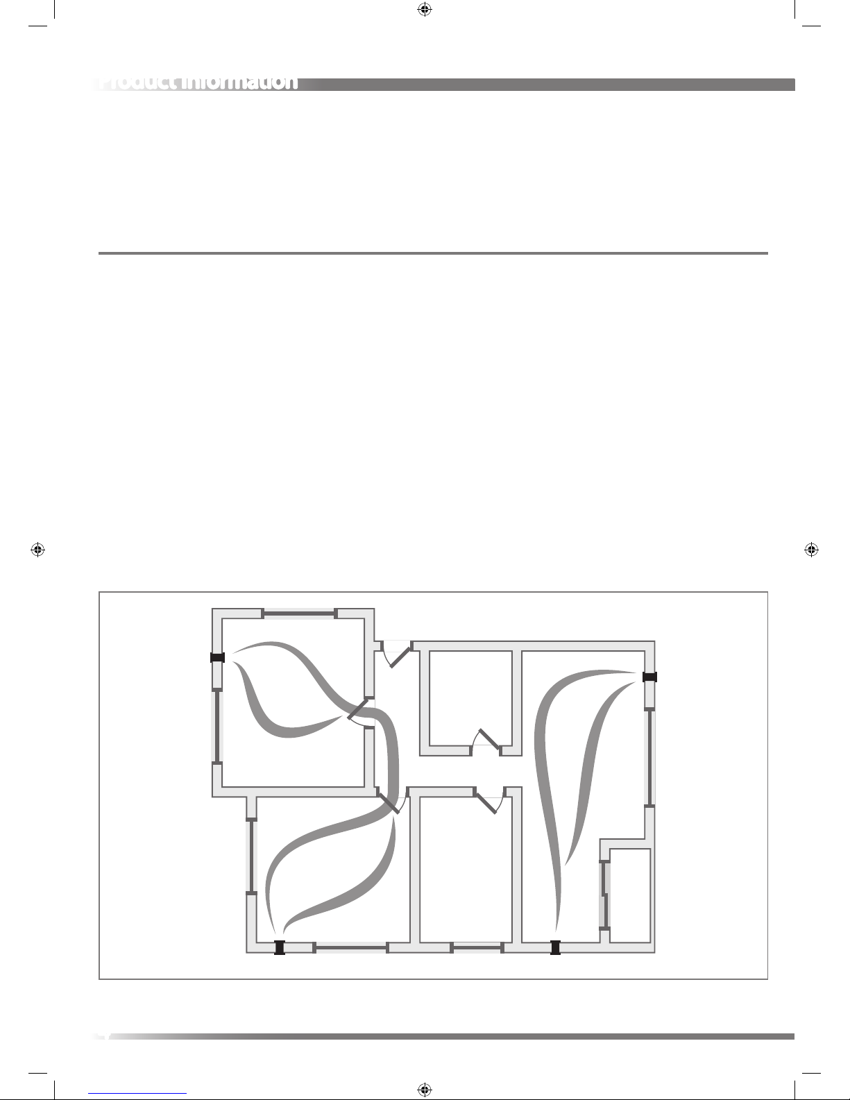
Designed to be used in pairs and in conjunction with a SRC1 the SR700s create a balanced decentralised ventilation system with heat recovery.
As part of a system multiple units provide continual air circulation for your home, extracting stale moist air and replacing it with warmed fresh
air from outside.
The system provides an easily installed and maintainable solution for removing internal condensation and eliminating mould growth within the
home. Unlike regular extractor fans that waste 100% of heat that passes through them from the home, the SR700 system will recover up to 94%,
based on in house testing, of wasted heat. When used as part of a whole house system it can be used to recover heat or provide continuous
fresh air without heat recovery.
Benets and Features
Achieves 20Pa back pressure as per BS EN 13141-8:2014.
6 SR700s can be connected to one SRC1.
Easy to maintain.
Low noise and vibration level due to expanded polypropylene housing.
Low prole wall mounted facia.
No additional duct work required.
Sleep mode sets the unit to its function at its slowest running. Returning to normal function after a set time.
Humidity mode provides ventilation rates suitable for when dwellings are unoccupied.
Intensive ventilation (Manual) to quickly remove any odours that are present.
Intensive ventilation (Automatic) to quickly remove excessive amounts of moisture and dangerous levels of Carbon dioxide in the dwelling
– (optional sensor required).
Cross ventilation mode for a constant ow of fresh cool air through the house without heat recovery.
Suitable for wall thicknesses of between 305mm to 700mm.
The ventilation rate for the SR700 can be congured for both large and small dwelling via the fan settings option in the service menu.
System Layout
Page 5
5
Packaging Contents
Inspect the units when taking delivery. Check the units for damage and that all accessories have been supplied.
SR700 Fan Unit
Package supplied with:
SR700 Fan unit x 1;
Product Installation Manual x 1.
Any shortages or damage must be immediately reported to the supplier.
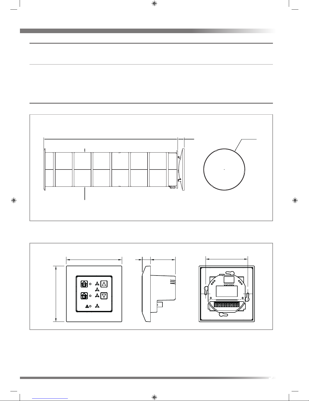
Dimensions & Component Identication
Fan Unit
711
34.5
Ø220.4
Ø180
Controller Unit
80
60.8
80
12
36
Page 6
6
Installation
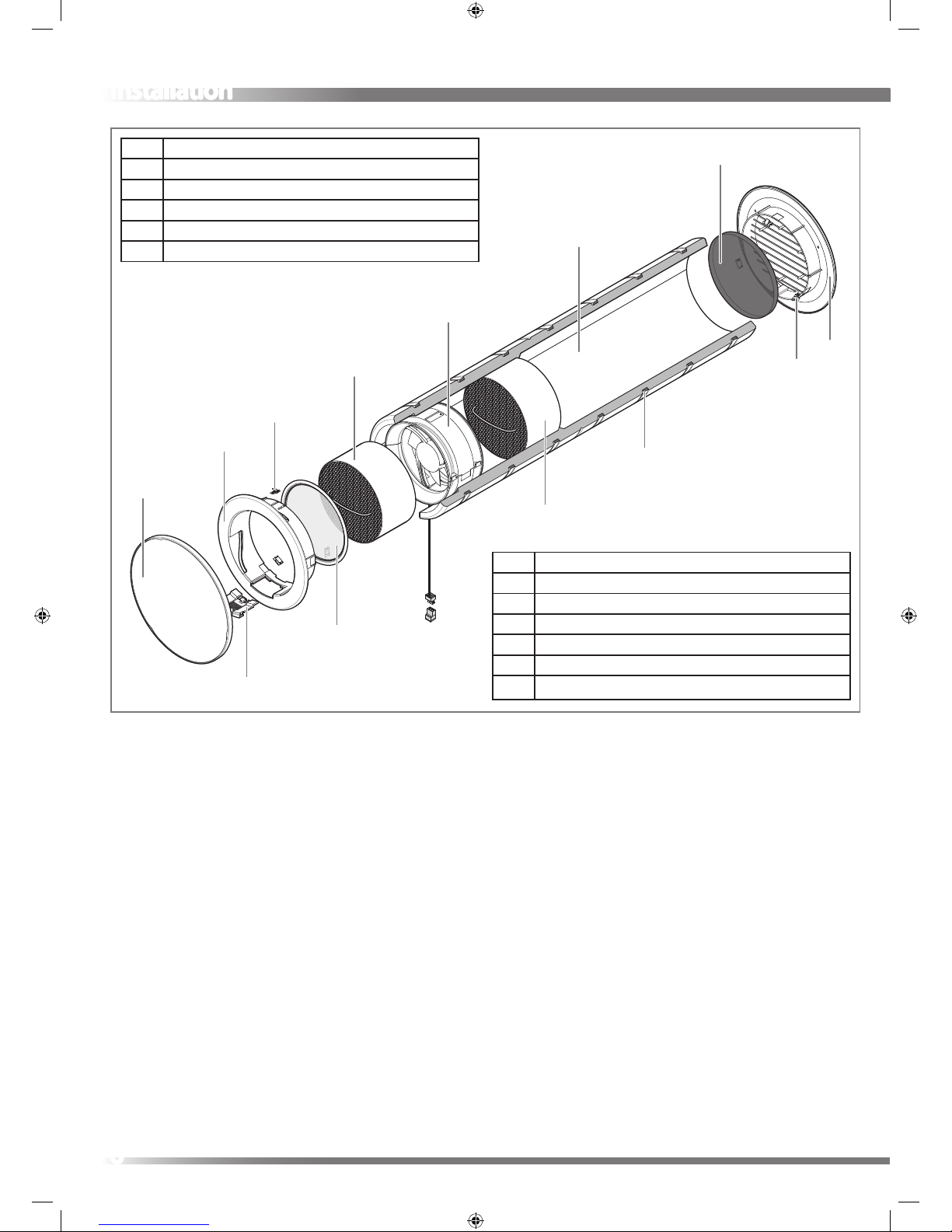
SRHRV Fan Unit ‑Components
1
2
3
4
4
5
6
6
9
7
8
10
11
No. Component
1 Diuser
2 Bezel
3 Wiring Aperture Cover
4 Spring Steel Clip
5 Air Filter
No. Component
6 Heat Cell
7 Fan with Connectors
8 Vent Tube
9 Foam Strip Seal positions (not supplied)
10 Foam Fly Screen
11 External Louvre
Page 7
7
SRHRV Fan Unit
Read and observe the guidance & safety notices listed in Warnings, Safety Information and Guidance .
The Titon SRHRV Fan unit is designed to be mounted through a wall with a thickness between 305mm & 700mm.
Consider the positioning of electrical services when siting the Fan Units and Controller.
Hole Preparation
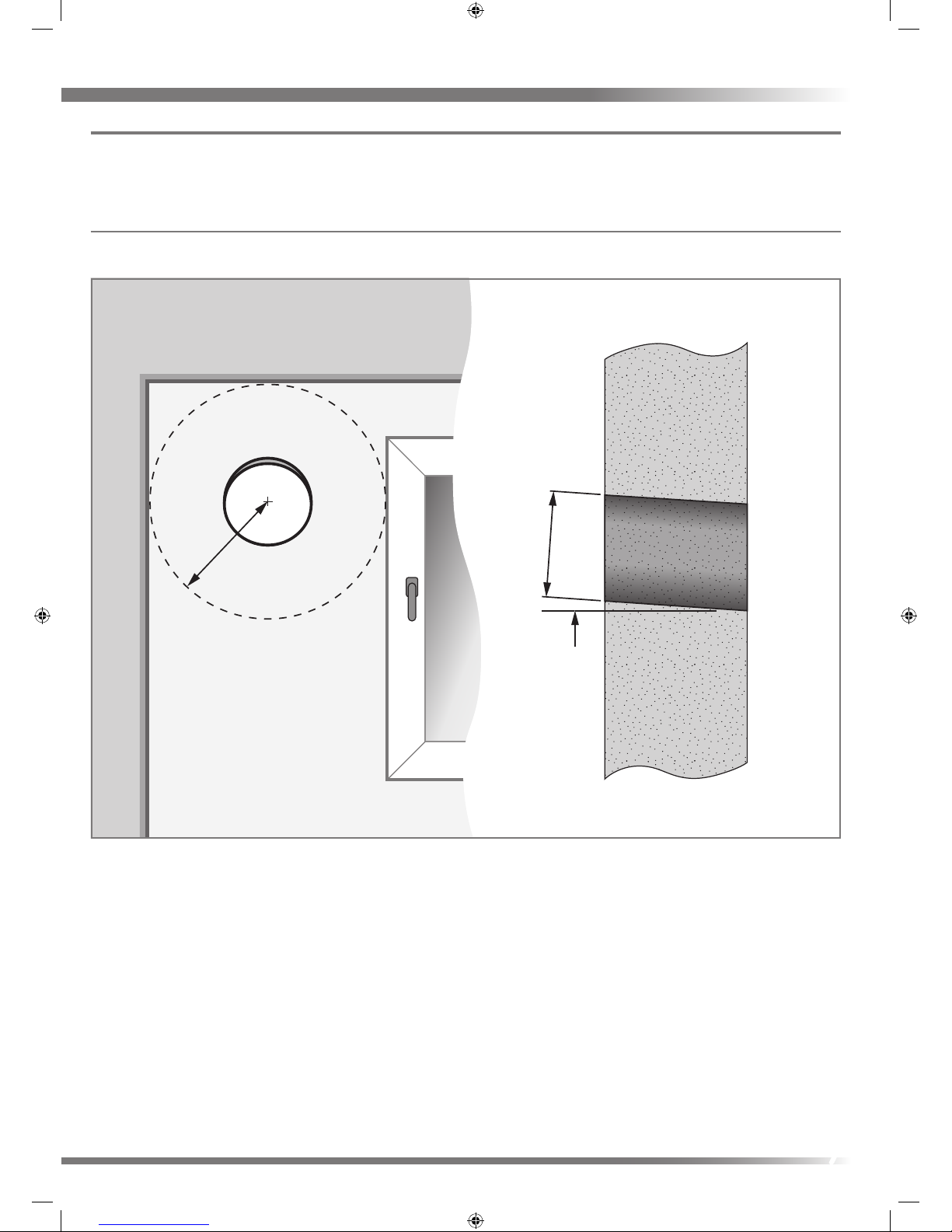
1. Position SRHRV Fan unit(s) ensuring clearances required between adjacent wall(s), window(s) and ceiling are adhered to.
2. Drill Ø182mm hole through the wall with a fall angle of 1° to 2° towards the outside .
Hole Preparation
Ø182
≥250
1-2˚
Inside Outside
Page 8
8
Vent Tube
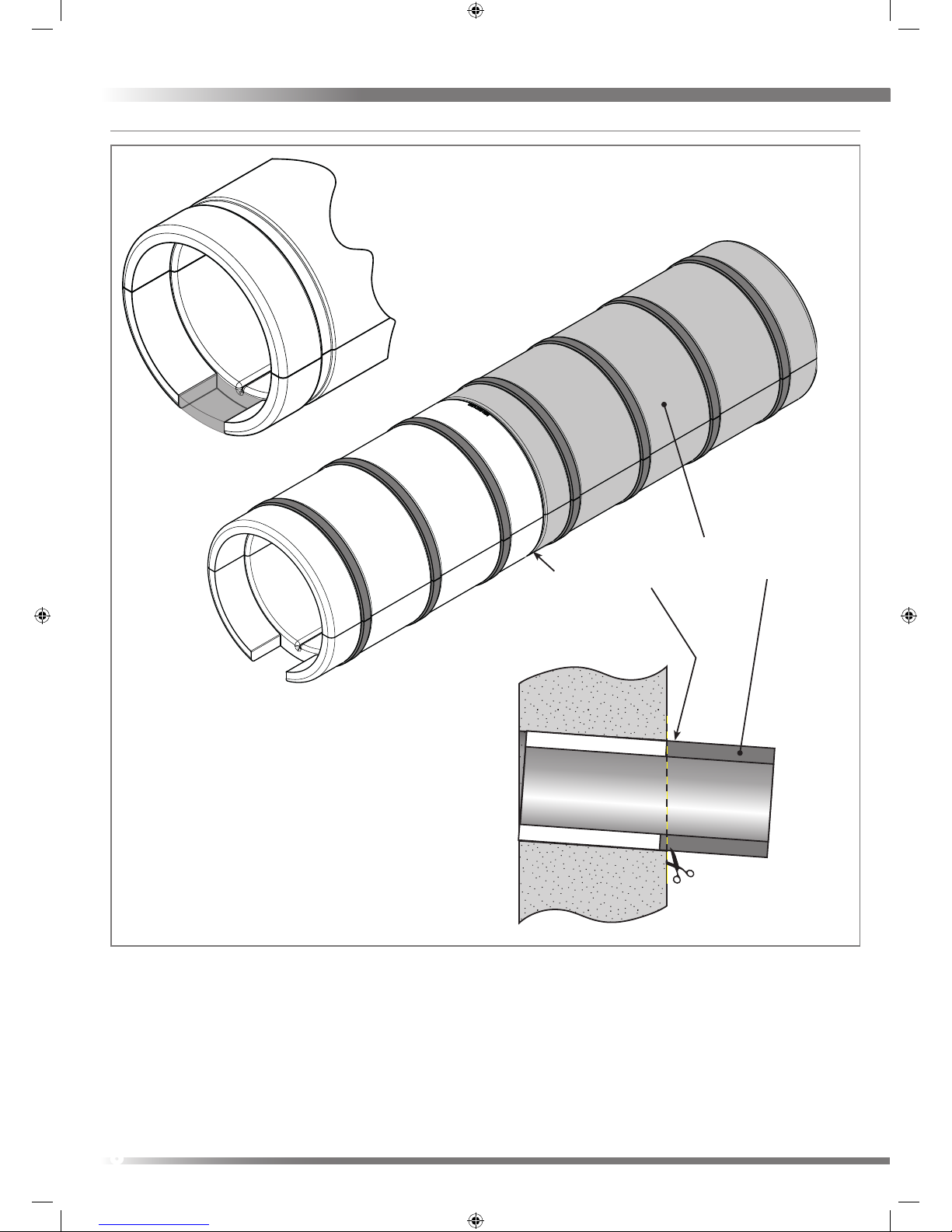
3. Prepare Vent Tube. Cut out one of the Wiring Pockets Using a sharp blade, cut out the material highlighted to create an aperture to
accommodate the 12v fan connection, g 1.
4. Fit Seals. Fit minimum of three self-adhesive expanding foam strips (not supplied). in to the channels around the diameter of the vent
tube. Ensure channels at either end of the tube are occupied.
5. Slide Vent Tube into hole, ensure that the internal lower edge of the Vent Tube is ush with the nished interior surface and that the Wiring
Pocket is orientated to suit the wiring.
6. Trim excess Vent Tube ush with the exterior nished surface, g 2.
Installation, Cutting & Orientation
Min Cut Line
Area that can
be removed.
Inside
Inside
g 2
g 1
Outside
Outside
Page 9
9
External Louvre
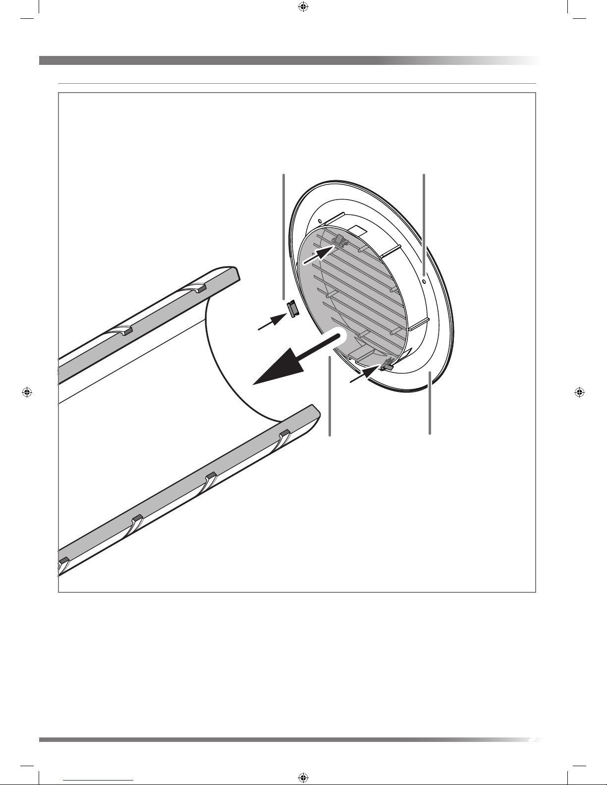
7. Fit three of the Spring Steel Clips to the positions on the External Louvre.
8. Fit External Louvre. Louvre is a push t. If screw xing is desired drill out the three screw ports from the inside to the outside of the
External Louvre using a Ø4mm drill. Fix the External Louvre to the Vent Tube using three 3.5mm x 32mm Pan Head PoziDriv® Self Tapping
Screw Form C to DIN 7981C ~ISO 7049 A4 Stainless Steel.
9. The External Louvre also has an area where sealant can be applied to seal the underside of the External Louvre's ange to the surface of the
building's exterior nish.
External Louvre, Screw Ports and Sealant Groove
9
8
7
8
Page 10
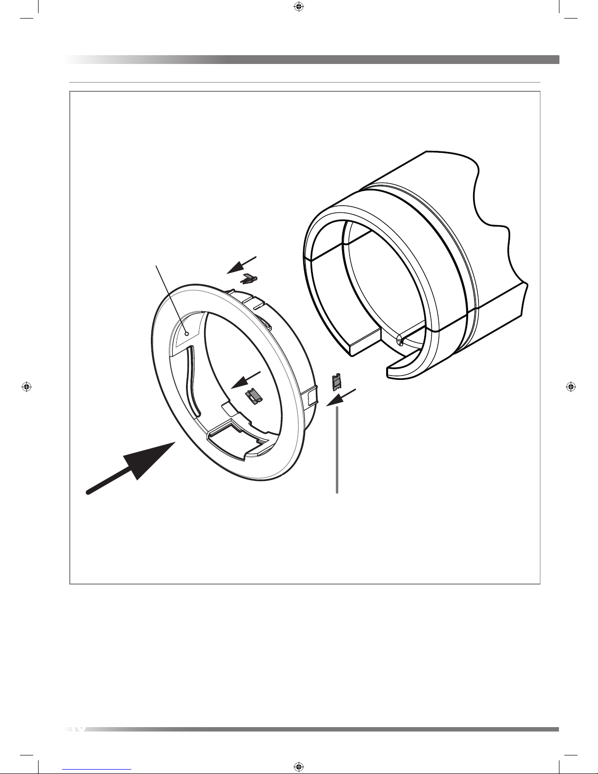
10
Internal Bezel
10. Fit the remaining three Spring Steel Clips to the positions on the Internal Bezel.
11. Fit Internal Bezel. Internal Bezel is a push t into the Vent Tube, when tting ensure Wiring Aperture is aligned with the Wiring Pocket in the
Vent Tube.
Internal Bezel
10
11
Note: Position of serial label to be
visible when installed.
Page 11
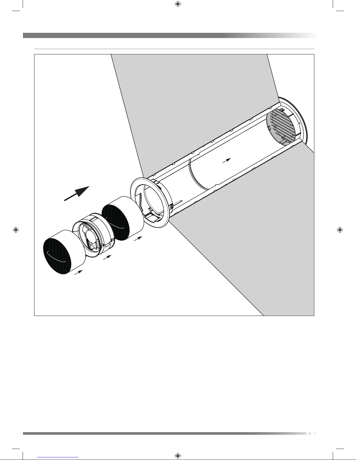
11
Internal Components
12. Fit the rst Ceramic Heat Cell. Slide a Ceramic Heat Cell into the Vent Tube. Ensure the Wire Handle is facing the inside and that the
Ceramic Heat Cell is pushed up against the stop in the Vent Tube.
13. Fit the Fan. Slide the Fan into the Vent Tube. Ensure the control wires are pushed into the Cable Groove and the Connection Plug is fed into
the Wiring Aperture. Also ensure that the Fan is pushed up rm against the rst Ceramic Heat Cell. Orientation of the Fan - Label must face
into the dwelling.
14. Fit the second Ceramic Heat Cell. Slide the Ceramic Heat Cell into the Vent Tube. Ensure the Wire Handle is facing the inside and the
Ceramic Heat Cell is pushed up against the Fan.
Fit Internal Components
Page 12
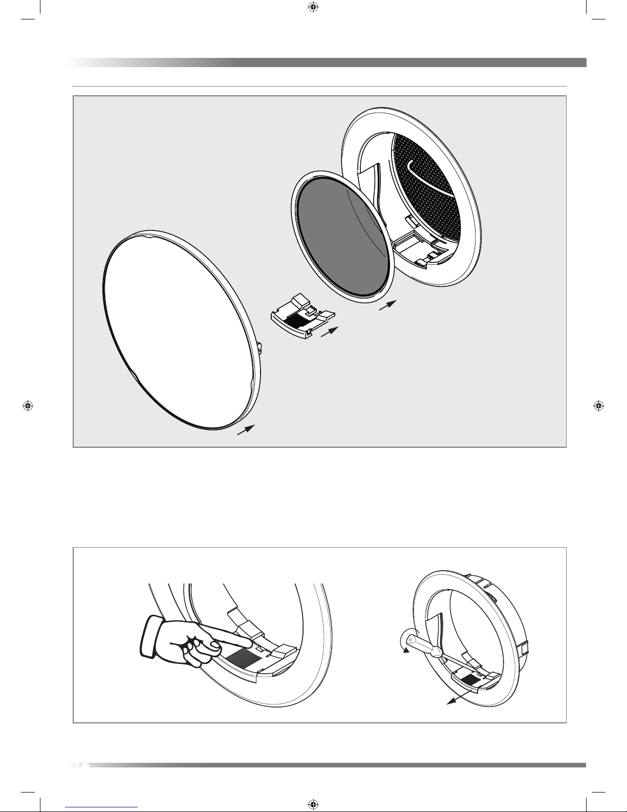
12
Diuser
15. Connect the Fan Cable. Using the push connector connect the Fan Cable to the Communication Cable, see wiring section for details.
16. Fit the Air Filter, which is held in place by the Wiring Aperture Cover.
17. Fit the Wiring Aperture Cover. Clip the Wiring Aperture Cover in place ensuring the wiring is not strained
18. Fit the Diuser. Clip the Diuser to the Internal Bezel ensure that all three clips are engaged and the Diuser rotates freely from the closed
to fully open position. Remove the protective lm from face of diuser.
Fit Wiring Cover and Diuser
How to remove Wiring Cover
Page 13
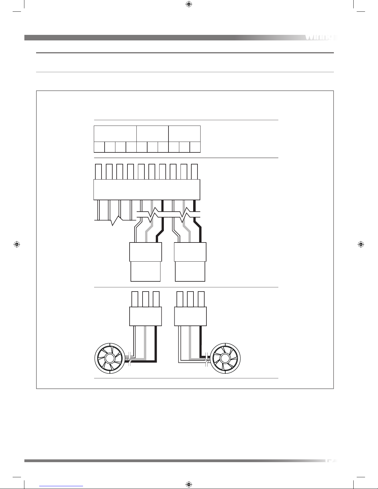
13
Wiring
Fans
Connection
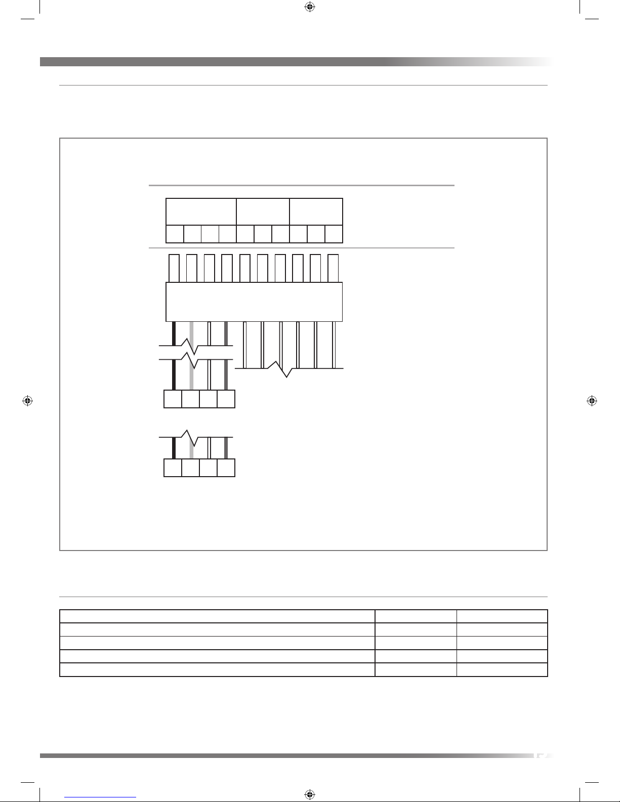
Connection of Fan Unit(s) to Controller is to be made with specied communication cable. Up to 3 pairs (six fans) can be connected to the
controller by connecting multiple cables to each terminal or by using a separate larger capacity connector.
Connect Wiring
+-
A
BUS
B + - + S
FAN 1
- + S
FAN 2
-
Extract Supply
Controller SRC1
Extension Cable
(Installer supplied)
Fan
+-
-
++-
Page 14
14
SRC1 Controller Unit
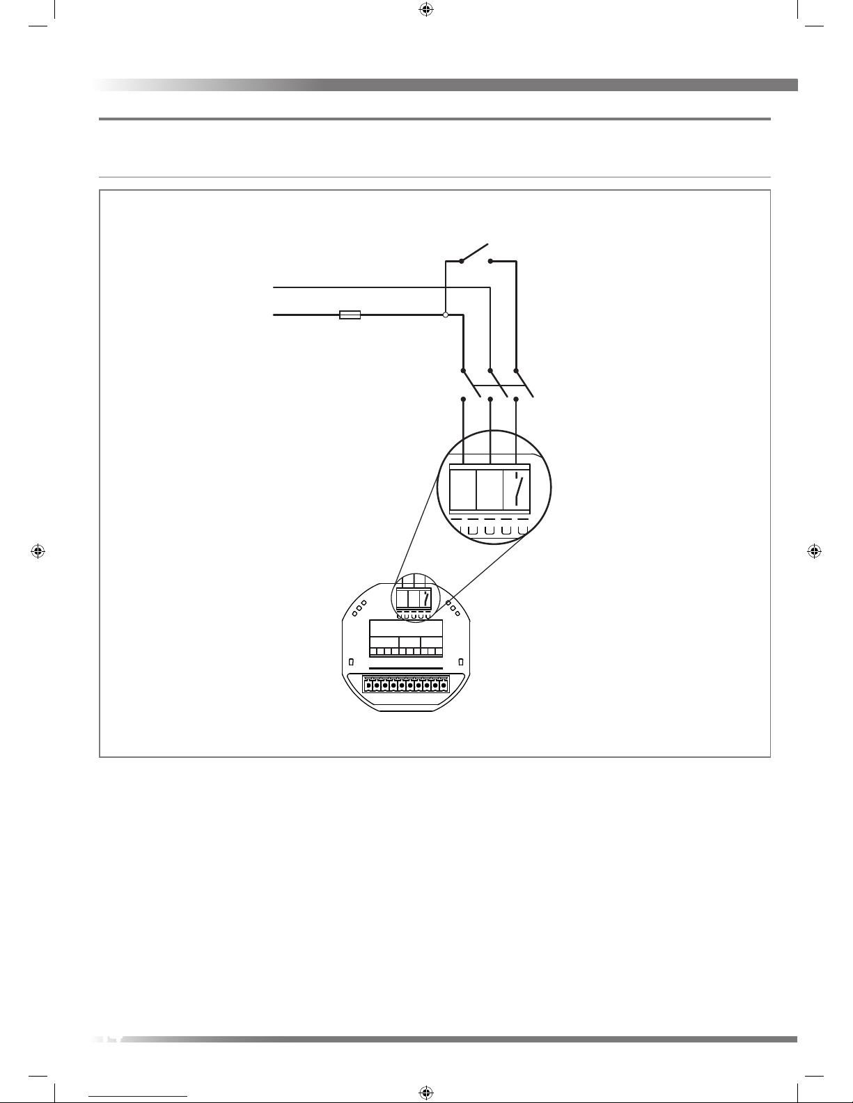
All necessary control components are integrated in this device. The SRC1 Controller is designed to t into a single ush mounting wall box.
Mains
L1 N
L1 N
A
BUS
B + - + S
FAN 1
- + S
FAN 2
-
N
L
Fuse
All Pole
Isolator
External Digital
Input Switch
(optional)
see note
220-240V~
50-60Hz
Mains Connection ref EE191
Note: It is mandatory that the External Digital Input Switch is supplied from the same phase as the SRC1 to avoid the risk of high voltage,
which could cause damage to the controller.
Page 15
15
Sensors
A
BUS
B + -
4 3 2 1
+ S
FAN 1
- + S
FAN 2
-
Extract Supply
Surface Mount Sensors
Flush Mount Sensors
Controller SRC1
A B + -
Sensor to controller connection
Sensor Options
Sensor type Surface mount Flush mount
Relative humidity (RH) sensor TP610 TP614
Carbon dioxide (CO) sensor TP611 TP615
Combined relative humidity (RH) & Carbon dioxide (CO) sensor TP612 TP616
Volatile organic compound (VOC)/ Air quality sensor TP613 TP617
Page 16
16
Commissioning & Controls
Operation
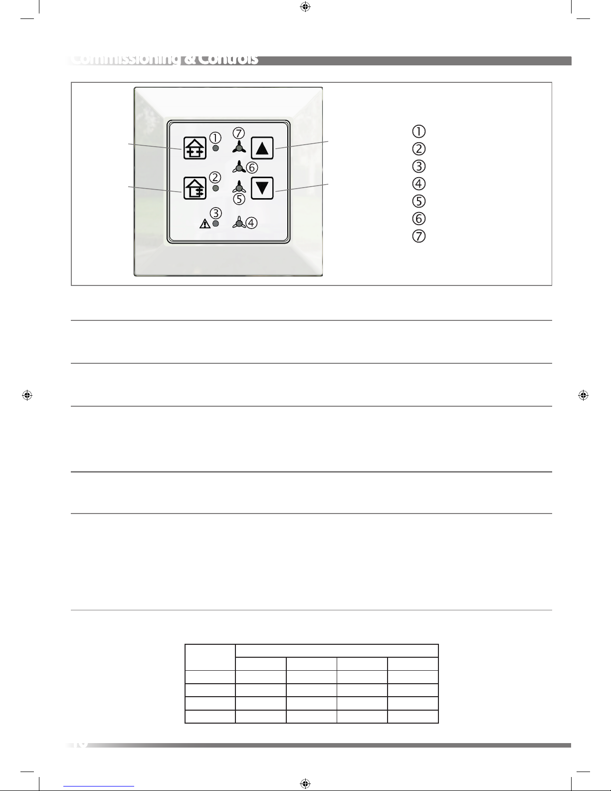
The fans can operate either in heat recovery mode (default) or in cross ventilation mode. In heat recovery mode, the fans will change direction
periodically. In cross ventilation mode, the fans will not change direction.
Heat Recovery Mode
In Heat Recovery Mode the Supply and Extract fans change directions at regular intervals, warming the Heat Cell when extracting from the
dwelling and recovering the stored heat when supplying air to the dwelling. This is the default operating mode.
Cross Ventilation Mode
In warm weather when heat recovery is not required Cross Ventilation mode simply supplies air to one side of the dwelling and extracts from
the other to create a cooling ow of air. By default Cross Ventilation is continuous, but it may have a timer congured by the installer (4, 8, 12 or
24 Hours). If a timer has been selected this will be indicated by LED 1 slowly ashing and once the timer has expired the controller will return to
Heat Recovery mode. A second press of the Cross Ventilation button switches from timer to continuous.
Fan Speeds
The device can run 4 dierent fan speeds as dened by DIN 1946-6
Fan setting 1 (Large dwelling)
Sleep Mode** 6.5m/h or O
O**
Humidity Protection 6.5m/h
Reduced 20m/h
Nominal 40m/h
Intensive 60m/h
Fan setting 2 (Small dwelling)
Sleep Mode** 6.5m/h or O
O**
Humidity Protection 6.5m/h
Reduced 10m/h
Nominal 17m/h
Intensive 25m³/h
**Congurable in the service menu
Sensor Mode
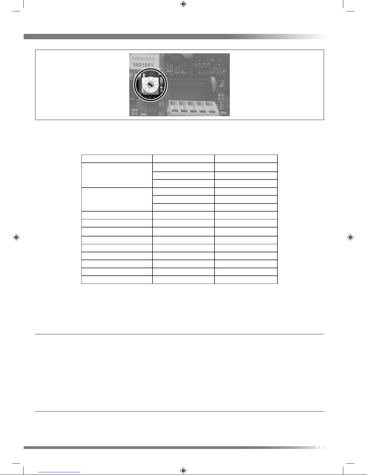
When sensors are used, the number connected is entered via the Service Menu and the correct number selected on each sensor encoder (see
image). See below table for encoder settings.
Quantity of
Sensors
Encoder settings
Sensor 1 Sensor 2 Sensor 3 Sensor 4
1 0 X X X
2 0 1 X X
3 0 1 2 X
4 0 1 2 3
Controller
Increase
Speed
Decrease
Speed
Humidity protection
Cross ventilation
Heat recovery
Error
Reduced speed
Nominal
Intensive speed
Increase
Speed
Cross
Ventilation
Decrease
Speed
Heat
Recovery
Page 17
17
The type of sensor will be detected automatically. For every type of sensor there are 3 threshold levels. The parameters are Humidity, CO and
VOC threshold. For humidity only, one of three dierent sets of thresholds can be selected in the service menu. See below table of thresholds.
Function threshold Fan speed Threshold value
CO
2
threshold 2 800ppm
3 1000ppm
4 1200ppm
VOC threshold 2 800ppm
3 1000ppm
4 1200ppm
Humidity threshold low 2 35 %RH
Humidity threshold low 3 50 %RH
Humidity threshold low 4 65 %RH
Humidity threshold medium 2 40 %RH
Humidity threshold medium 3 55 %RH
Humidity threshold medium 4 70 %RH
Humidity threshold High 2 45 %RH
Humidity threshold High 3 60 %RH
Humidity threshold High 4 75 %RH
Whenever the lowest threshold is exceeded, the fan level will be set to the reduced fan level. The second threshold will trigger the nominal fan
level, and the third sensor threshold will request the intensive fan level. The fan level will be active until the corresponding threshold is undercut.
There is a hysteresis of 5%RH or 50ppm active when switching between the fan levels. Whenever the current fan level is manually altered, the
sensor driven fan level will be deactivated for the duration of 1 hour.
Sleep Mode
The SRC1 has a digital input which is used to activate Sleep Mode. The digital input requires a 220-240V~ supply via a switch, see Wiring, Mains.
It is mandatory that the External Digital Input Switch is supplied from the same phase as the SRC1 to avoid the risk of high voltage, which
could cause damage to the controller.
Operating the switch puts the unit into Sleep Mode; By putting the unit to sleep, fans can be congured to either stop (default) or slow to
humidity protection level for a period of time (default 1 hour) after which they will return to the previous setting. A second switch operation
before the timer has expired brings the controller out of Sleep Mode. Sleep Mode can also be activated by pressing and holding the down arrow
on the SRC1 keypad. The length of time the unit remains in Sleep Mode is congurable in the Service Menu. It is also possible to congure the
fans to run at one of the other fan speeds during Sleep Mode.
Filter Monitoring
The control unit has an integrated lter timer. The timer will operate whenever the fans are running. When the lter timer has expired the
"ERROR" LED will illuminate continuously. The lter timer can be reset by holding both right hand side buttons for ve seconds. The reset will be
acknowledged by all LEDs ashing three times.
Sensor PCB, Encoder Highlighted
Page 18
18
Service Menu
The Service Menu can be used to congure external sensors and adjust other controller parameters and is based on the buttons and the LEDs.
In order to enter the service menu, the two left buttons have to be held for at least ve seconds. When in service mode, all three LEDs on the
left side (cross ventilation, heat recovery and error) will be activated, either ashing or permanently lighting up. By these three LEDs, the current
active service menu can be identied. When in service mode, the two left buttons can be used to move through the dierent settings of the
service menu. The right hand side buttons will change the selected parameter value. The three LEDs on the right side will be used to show the
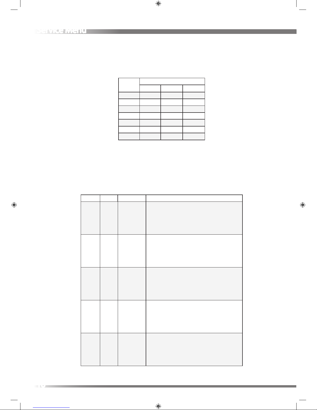
value of the currently selected parameter. Each LED combination will represent a parameter value as shown in the table below.
Value
LED Number
5 6 7
1 1 0 0
2 0 1 0
3 1 1 0
4 0 0 1
5 1 0 1
6 0 1 1
7 1 1 1
Whenever a value has been edited, it has to be saved rst, in order to take eect. To save the edited value, the button on the top left has to be
held for three seconds. The saving will be acknowledged by a ashing of the right side LEDs.
In order to leave the service menu, the left bottom button must be held for three seconds. The Controller will switch back to the normal
operation display. Whenever no button is pressed for a period of two minutes, the Controller will fall back to normal operation display.
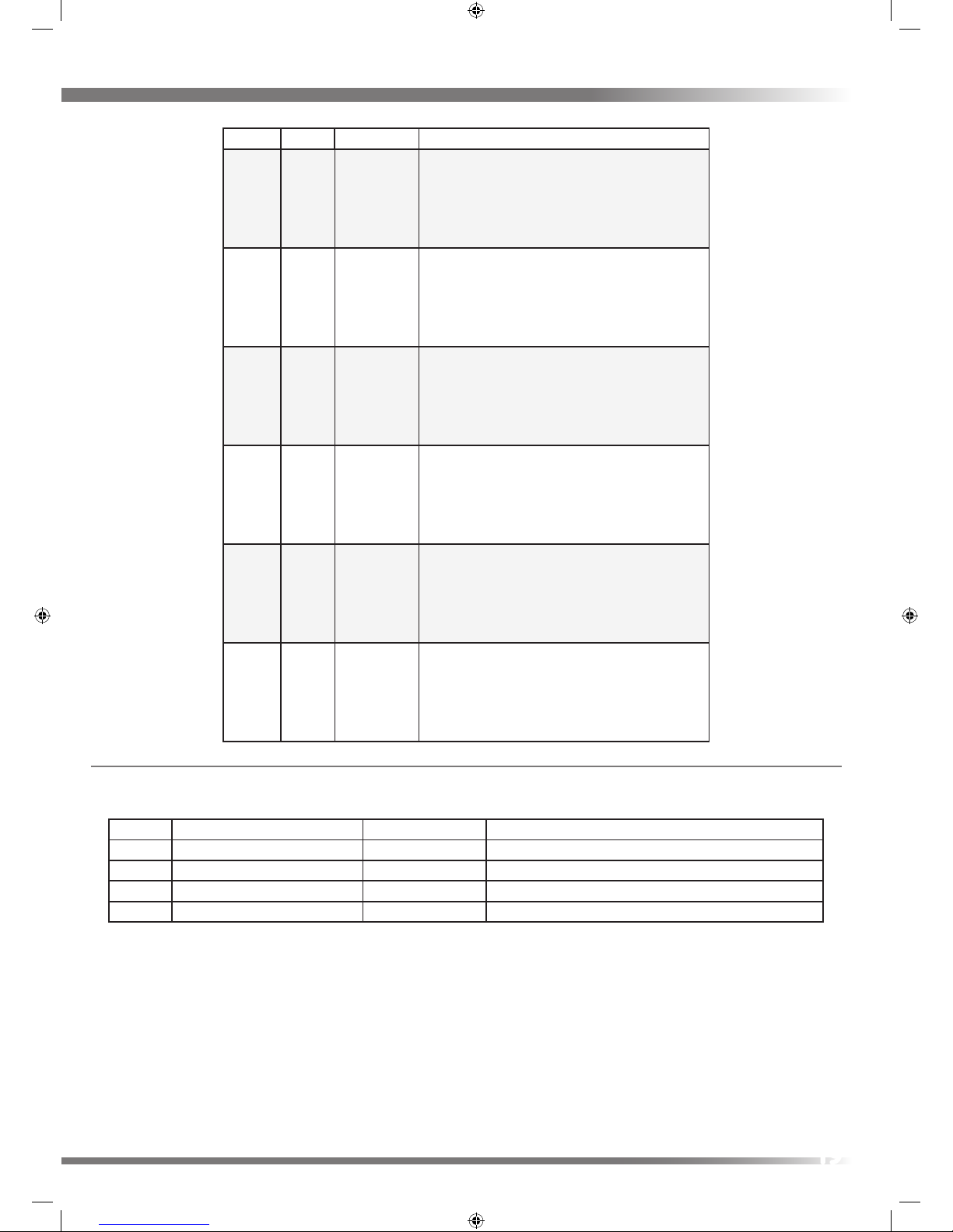
The dierent parameters in service menu are shown in the table below.
Number LED Display Menu
1
1
2
3
ON
ON
OFF
Number of sensors
1=no sensors (Default)
2=1 sensor
3=2 sensors
4=3 sensors
5=4 sensors
2
1
2
3
ON
ON
FLASH
Duration of sleep timer, mins
1=15
2=30
3=45
4=60 (Default)
5=120
3
1
2
3
ON
OFF
ON
Fan level in sleep mode
1=OFF (Default)
2=level 1
3=level 2
4=level 3
5=level 4
4
1
2
3
ON
FLASH
ON
Duration of times intensive ventilation, mins
1=15
2=30
3=45
4=60 (Default)
5=120
5
1
2
3
OFF
ON
ON
Duration of cross ventilation, hours
1=permanent (Default)
2=4
3=8
4=12
5=24
Page 19
19
Number LED Display Menu
6
1
2
3
FLASH
ON
ON
Function of digital input
1=sleep timer (Default)
7
1
2
3
FLASH
ON
OFF
Fan level o allowed
1=not allowed (Default)
2=allowed
8
1
2
3
FLASH
ON
FLASH
Sensor sensitivity
1=low
2=medium (Default)
3=high
9
1
2
3
FLASH
OFF
ON
LED brightness
Increase and decrease using UP and DOWN arrows.
10
1
2
3
ON
FLASH
FLASH
Fan selection
1=Fan settings 1 (Default)
2=Fan settings 2
11
1
2
3
FLASH
FLASH
FLASH
Factory Defaults
6=restore factory defaults
Errors
LED 3 is used to indicate errors which may occur with the controller. The number of times the LED ashes followed by a pause indicates the type
of error, these are detailed below:
Number Error Error LED Indication Recommended Action
1 Filter Timer expired LED ON Replace/Clean Filters & Reset Timer.
2 Self test failed 2 x FLASH - PAUSE Contact the installer.
3 Sensor Communication error 3 x FLASH - PAUSE Check wiring to the sensor(s), contact the installer.
4 Controller temperature too high 4 x FLASH - PAUSE Contact the installer.
Page 20

MARKETING DIVISIO N
894 The Cr escent , Colche ster Bus iness Pa rk,COLCHESTER , CO4 9YQ
Tel : +4 4 (0) 1206 713800 Fa x: +44 ( 0) 1206 543 126
Email: vent sales@tito n.co.uk Web: w ww.titon.com
©2017 TITON DO 5482 Iss 05
 Loading...